
Home / Case Studies / Capacitive Touch Control Panel
Anonymous engineering case
Capacitive Touch Control Panel Approved as an Installed Signal Chain
A printed capacitive touch panel is only the visible end of the control system. Cover material, ink, electrode geometry, bonding, tail routing, controller settings, ground, nearby metal, display noise, enclosure fit and host response all shape what the operator experiences.
This representative case explains how to review those interfaces before production release. It does not identify a customer or claim a controller, glove, water, noise, EMC, ESD or equipment result that has not been defined and tested for the actual project.
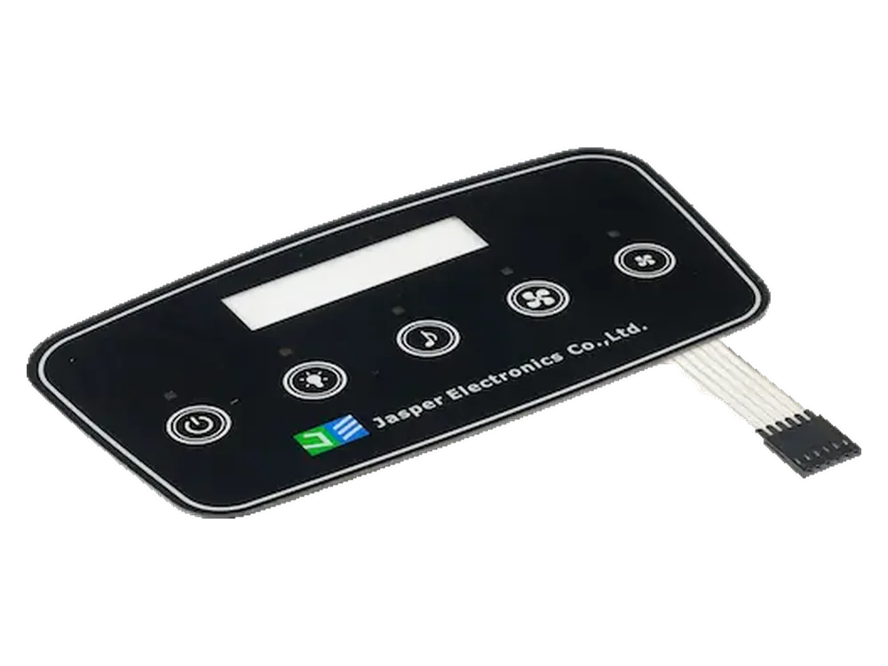
Approve the installed chain, not only the printed front
A loose panel can respond correctly on a quiet bench and behave differently beside the production display, metal bezel, power supply, cable set and enclosure. The sample plan should therefore name the cover stack, sensor map, tail, controller and firmware revision, ground and shield boundary, host response, input states and representative equipment used for approval.
Project input framework
The first useful review joins five groups of information that are often held by different teams.
Touch behavior follows the complete installed signal path
The operator first couples through the cover and printed stack. The electrode converts that change into a small electrical signal. The tail and connector add routing and parasitic effects before the controller decides whether an event is valid. The host then accepts, rejects or reports the command.
Display electronics, metal, ground, enclosure geometry, feedback and power state can influence different points in that path. Their effect cannot be judged from the artwork file alone, and responsibility should not be left between the mechanical, electrical and software teams.
The purchased scope must also be explicit. A printed cover, a sensor-and-tail assembly, a programmed controller board and a complete HMI front are different deliverables. Sample evidence should match the scope named in the quotation and controlled drawings.
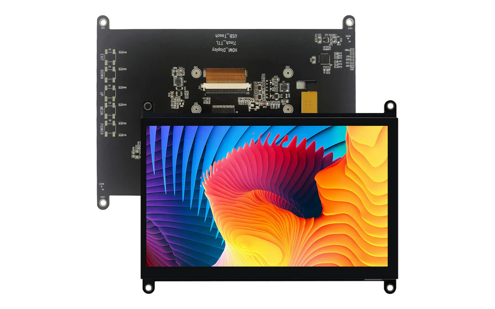
Five interfaces must be reviewed together
Most late problems sit at a boundary between parts rather than inside one isolated drawing.
Cover, print and bonding
Material, thickness, coating, second-surface print, local ink build, adhesive and air gaps change the dielectric path and the relationship between the visible icon and the sensor below.
Electrodes and neighboring features
Sensor size, spacing, edge location, sliders, wheels, LED openings, display borders, guards and routing need the real cover and nearby conductor map.
Tail, connector and controller
Raw sensor lines and controlled digital interfaces have different routing risks. Tail length, connector, channel map, controller location and configuration should be settled before mechanical release.
Ground, metal and display
Chassis, bezels, brackets, fasteners, shields, display electronics, LED current paths and other conductors can alter sensitivity or introduce noise. Their installed positions belong in the review.
Enclosure and host behavior
Support flatness, gasket pressure, assembly access, startup logic, event rejection, feedback and recovery determine whether a detected touch becomes a usable equipment command.
Review four operating and recovery states
A single dry-finger demonstration does not define the product. The sample report should record the expected event, rejected event, feedback and recovery for each agreed state.
Dry bare finger
Confirm the normal touch map before adding harder conditions
Check every key, slider, wheel, edge and corner that belongs to the specification. Record adjacent-key behavior, simultaneous inputs, feedback, latency expectation and any intentionally inactive area.
Specified glove
Use the actual glove type and operating posture
Glove material, thickness, fit, fingertip contact and operator angle change coupling. Approval should identify the glove and the controller revision instead of using a general glove-compatible claim.
Cleaning or moisture
Define contact, film and recovery rather than saying waterproof
Name the liquid or cleaner, amount, contact location, dwell, wiping method and expected response during and after exposure. Separate false-touch rejection from any enclosure sealing requirement.
Startup and noise
Observe power transitions, display activity and fault recovery
Review power-up, wake, reset, charging or switching events, display states and cable arrangements relevant to the equipment. Record how the host reports, rejects or recovers from an abnormal event.
The first installed sample must answer four questions
These questions convert a broad request for a capacitive control panel into a controlled sample decision.
Which cover, print, adhesive and gap configuration is being approved?
Control the complete dielectric stack and its tolerances. A substitute cover, coating, ink, label, adhesive or unplanned air pocket can change the sensor response.
How do visible targets relate to electrodes, routes and neighboring conductors?
Use shared datums for icons, electrodes, display areas, LEDs, tail exit, metal and enclosure. Approve edge and adjacent-key behavior, not only the easiest center key.
Who owns the controller, configuration, firmware and host decision?
Record the exact boundary, channel map, power and interface states, programming file, diagnostics, feedback and change approval. Do not describe a physical panel as tuned when that scope is not included.
Which installed states and acceptance records release the design?
Link the sample to the representative display, enclosure, cable, ground, power condition, controller revision, state matrix, photographs or logs, and signed drawing revision.
A four-step sample approval sequence
The purpose of the first article is to freeze a reproducible interface between the manufactured panel and the buyer's installed system.
Align the drawings and responsibility table
Place cover, artwork, touch targets, electrodes, display, LEDs, tail, connector, metal, ground and enclosure on controlled datums. Assign ownership for controller, firmware and final equipment validation.
Verify the manufactured panel before installation
Inspect print registration, surface, bonding, sensor mapping, tail orientation, pinout, connector, continuity and agreed electrical outputs before the panel enters the equipment.
Install the sample in representative hardware
Use the planned cover support, adhesive or gasket, display, metalwork, fasteners, cables, power source, controller and host build. Avoid approving only a hand-held bench assembly.
Approve the state matrix and revision package
Record normal touch, glove, cleaning or moisture, startup, noise and recovery states that apply. Release the sample with drawings, configuration, evidence, exceptions and change-control rules.
Production controls for the physical touch-panel assembly
Manufacturing control should protect the released cover, sensor and interconnect. Controller tuning and final equipment behavior remain within the scope assigned by the project documents.
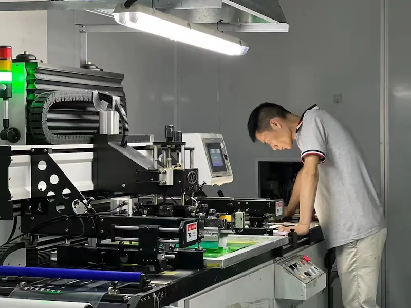
Printing and lamination
Graphics, dielectric stack and sensor position stay on the same datums
Print registration, curing, window and dead-front areas, adhesive conversion, liner handling and lamination must preserve the approved relationship between visible targets and the electrode construction.
- Artwork, color reference, icon centers, windows and controlled print zones checked before printing
- Adhesive openings, local stack changes and sensor alignment compared with the released drawing
- Surface, liner, contamination and cosmetic zones protected through conversion and packing
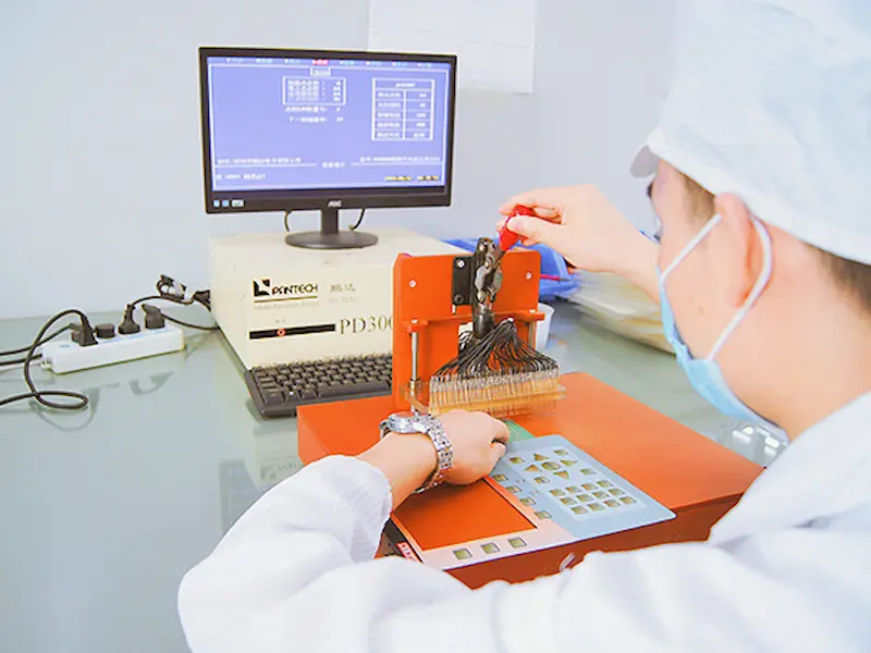
Circuit and tail inspection
Electrode mapping and interconnect leave production in a known state
The agreed inspection can check circuit continuity, mapping, tail contacts, connector orientation and defined panel-level outputs. It does not replace controller tuning or final powered-equipment validation.
- Released channel or node map compared with the circuit artwork and pinout
- Tail contact side, stiffener, connector orientation and handling features inspected
- Panel-level test record linked to the drawing and production revision
Six inputs needed before sample planning
A useful RFQ states the system boundary and difficult operating states, not only the front-panel dimensions.
Outline, material, thickness, coating, print side, colors, icons, windows, dead-front areas, cosmetic zones and surface exposure
Key, slider, wheel or coordinate areas, target sizes, simultaneous-touch rules, inactive regions, feedback and host action
Preferred construction, electrode constraints, tail exit, route, length, contact side, connector, pinout, bend and assembly access
Controller device or constraints, owner, channel map, firmware or configuration revision, power, interface, diagnostics and programming scope
Display, metal, chassis, ground, shield, LEDs, cable set, enclosure section, bonding or gasket, fasteners and likely noise sources
Bare finger, named glove, cleaning or moisture condition, startup, power, display, noise, false-touch, recovery and evidence method
Continue the technical review
Use these pages to compare product scope, sensing type, display integration, lighting, HMI assembly and mechanical-switch alternatives.
Questions before a similar RFQ
Can JASPER manufacture a custom capacitive touch control panel?
JASPER can review custom covers, printed graphics, touch-sensor constructions, tails, connectors, lighting features and front-panel assemblies. The quotation should state whether the controller, firmware, display and final equipment validation are included or supplied by the buyer.
Can touch sensitivity be approved before the final enclosure is ready?
Early samples can support development, but final approval should use representative cover support, display, metal, ground, cables, power, controller and enclosure geometry. An isolated bench result does not prove installed behavior.
Does a capacitive panel work with gloves or water?
That depends on the named glove or liquid condition, cover stack, electrode design, controller, configuration, enclosure and host logic. Define the operating and rejection states, then verify them on the project hardware.
Who should own the touch controller and firmware?
The project should assign ownership explicitly. Record the controller device, channel map, configuration, firmware revision, programming, diagnostics, host interface and change authority in the quotation and approval package.
What is the minimum information for an initial review?
Send the cover and enclosure drawings, artwork, touch-function map, display and metal locations, tail and connector needs, controller boundary, glove or moisture conditions, power states and sample acceptance priorities.
Define the installed touch system before releasing the panel
Send the cover stack, artwork, touch map, tail and connector, controller boundary, display, metal, ground, enclosure and operating-state matrix. JASPER can review the physical panel and identify the interfaces that still need project evidence before sample release.