Dongguan, Guangdong 523927, China[email protected]+86 136 3262 5290
Home / Products / Medical Electrode Pads / Custom EMG Electrodes
PRINTED DIFFERENTIAL ELECTRODE GEOMETRY FOR OEM SYSTEMS

Custom EMG Electrodes

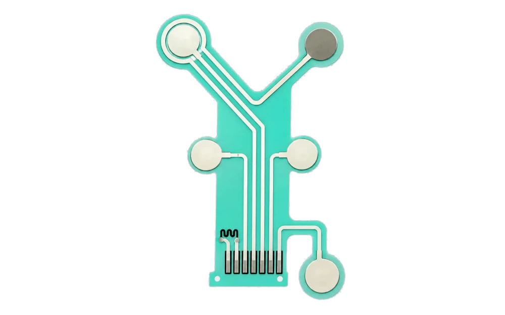
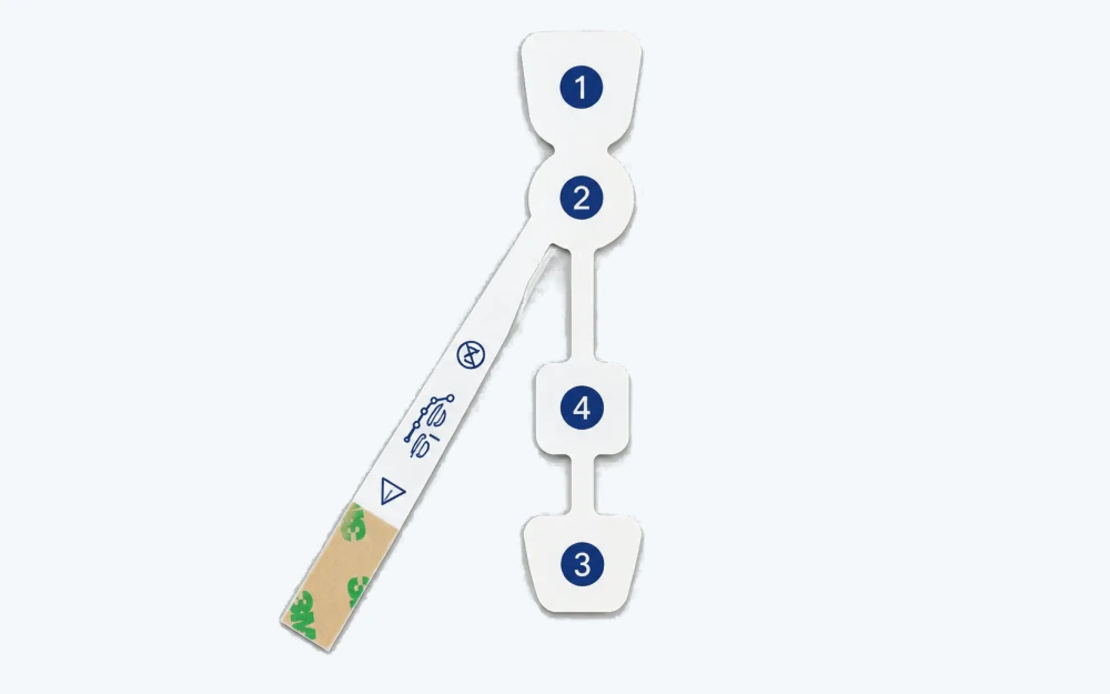
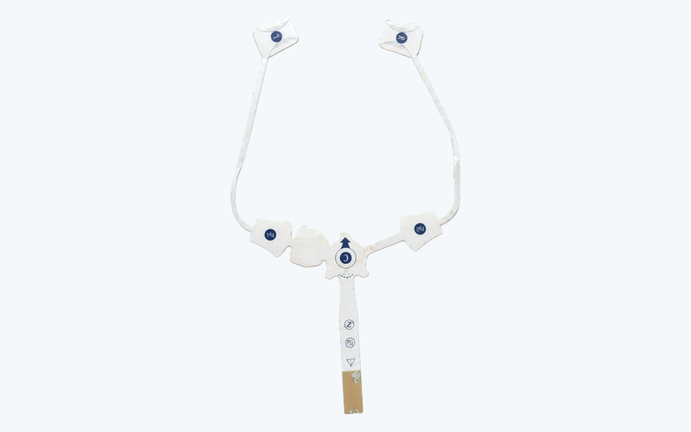
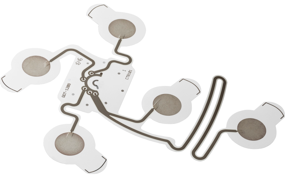
Custom flexible EMG electrode strip with paired printed sites and reference electrode

Custom EMG electrodes translate an OEM differential sensing layout into a repeatable printed and converted construction. JASPER can control paired or multi-site electrode spacing, reference geometry, printed traces, dielectric, flexible tail, connector, backing, project-specified adhesive or hydrogel zones, liner, die cut, and package. Placement, motion conditions, acquisition electronics, algorithms, and finished-device validation remain with the OEM.

Custom flexible EMG electrode strip with paired printed sites and reference electrode
Differential geometry controlledpaired sites, center spacing, reference position, orientation, and datum
Flexible circuit releasedtraces, dielectric, tail, connector, reinforcement, and converted material zones
OEM acquisition validationplacement, motion, electronics, filtering, interpretation, use, and regulatory pathway

EMG Electrode Performance Begins with Controlled Relative Geometry

For paired and multi-site EMG constructions, center spacing and orientation can be as important to the OEM design as the individual contact size. The circuit drawing should therefore release the complete relative geometry rather than isolated pad diameters.

JASPER can verify printed and converted features to agreed methods. The OEM evaluates placement, skin preparation, motion, cable forces, acquisition electronics, filtering, algorithms, intended use, and any clinical or regulatory claims.

Custom EMG Electrodes fit when:

  • paired or multi-site electrode spacing must remain fixed inside one flexible construction
  • a reference electrode, printed routing, tail, and connector need a controlled channel map
  • backing, adhesive or hydrogel zones, flexible regions, reinforcement, liner, and die cut can be project-released
  • the OEM owns acquisition performance, placement, motion, algorithms, clinical use, and finished-device validation

Six Controls for a Repeatable EMG Electrode Geometry

Release relative positions and mechanical handoff before choosing inspection fixtures.

01

Paired-site spacing

Release control

Dimension contact size, center distance, orientation, symmetry, tolerance, and placement datum.

If it is missing

The two sites are individually correct but their differential geometry does not match the OEM design.

02

Reference-site relationship

Release control

Release reference position, route, contact opening, channel identity, and connector assignment.

If it is missing

The reference path is shifted, mislabeled, or connected to the wrong interface.

03

Printed circuit and dielectric

Release control

Define traces, widths, clearances, insulation, bend regions, resistance, continuity, isolation, and registration.

If it is missing

Movement or conversion exposes conductors or changes the approved electrical path.

04

Tail, lead, and connector

Release control

Control tail exit, conductor order, reinforcement, connector, cable, strain direction, mating part, and retention.

If it is missing

The interface loads the patch or changes channel order during installation.

05

Converted material zones

Release control

Map backing, adhesive or hydrogel, foam or nonwoven, contact openings, flexible zones, liner, and edge margins.

If it is missing

Converted layers change contact exposure, flexibility, or the intended relative geometry.

06

Inspection and packaging

Release control

Define center spacing, site position, channel map, electrical method, attachment, liner, label, count, and package support.

If it is missing

The array is deformed or channel identity is lost after inspection.

Release the EMG Construction by Relative Geometry and Interface

Values must come from the OEM acquisition and use design, not from a generic electrode label.

DecisionOptions to ReviewRelease Question
Sensing layoutTwo-site differential pair, multi-site strip, reference site, center spacing, orientation, landmarks, and placement datumWhich relative geometry is functionally controlled?
Printed circuitInk, substrate, traces, contact openings, dielectric, guards, resistance, continuity, isolation, and flex zonesWhat electrical acceptance applies per route?
InterconnectPrinted tail, flexible cable, connector, pin map, reinforcement, bend keep-out, strain relief, and mating partHow does the OEM connect without loading the sensing geometry?
Converted stackBacking, adhesive or hydrogel zones, foam or nonwoven, liner, labels, edge margin, and handling tabWhich materials and zones are included in supply?
Mechanical acceptanceCenter spacing, outline, openings, tail exit, layer overlap, registration, flexibility, and package supportWhich dimensions require fixture or vision evidence?
Electrical and lot evidenceContinuity, resistance method, isolation, channel map, attachment, appearance, label, count, and traceabilityWhich checks prove manufacture without implying signal performance?
Printed EMG electrode geometry with paired sites, reference site, and routed traces
RELATIVE GEOMETRY

Inspect the Electrode Pair as One Controlled Measurement System

A fixture should locate the same datum used by the OEM placement method and verify site centers, reference position, tail exit, and orientation together. Checking each contact independently can miss the spacing error that matters to the acquisition layout.

  • dimension site centers and orientation from shared datums
  • retain channel names through the tail and connector map
  • separate printed tolerance from converted-layer tolerance
  • record geometry with the approved circuit revision
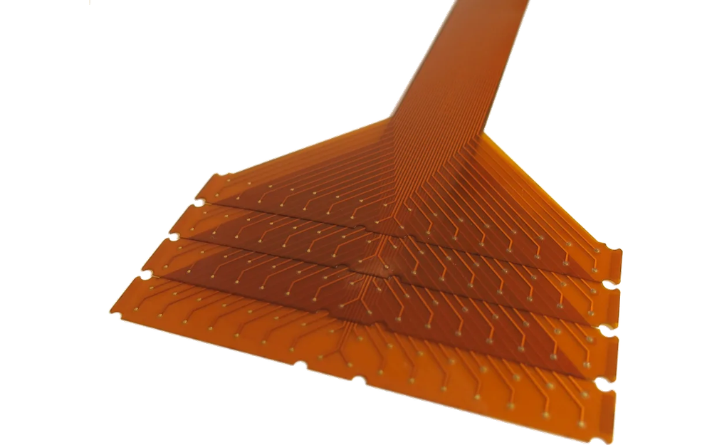
Exploded flexible layer stack for a custom EMG electrode
FLEXIBLE STACK

Keep Motion-Sensitive Areas Free of Unplanned Stiffness

Tail reinforcement, connector attachment, foam, backing overlaps, adhesive-free zones, dielectric, and packaging supports can create stiffness transitions. The OEM should identify areas where the patch must flex, while JASPER controls the released layer geometry.

  • map flexible, reinforced, adhesive, and contact zones
  • control trace transitions around tail and connector reinforcement
  • approve the converted sample in its packaged condition
  • assign motion and use validation to the OEM device program

Move from Printed Geometry to a Controlled OEM Handoff

01

Release sensing geometry

Define paired or multi-site positions, reference site, spacing, orientation, placement datum, and OEM validation.

02

Close the channel circuit

Release traces, dielectric, tail order, connector map, bend zones, and electrical acceptance.

03

Close flexible materials

Name substrate, backing, adhesive or hydrogel zones, reinforcement, liner, labels, and die cut.

04

Approve converted samples

Review spacing, registration, channel map, electrical checks, flexibility, attachment, liner, and packaging.

05

Control repeat production

Lock artwork, materials, connector, fixtures, records, package, substitutions, and requalification triggers.

Locate EMG Electrode Variation at the Correct Boundary

01

Differential spacing is outside target

Check circuit artwork, print registration, die-cut datum, converted-layer alignment, fixture, stretch, and package support.

02

Reference channel is incorrect

Compare site label, printed route, tail conductor, connector pin map, cable, test fixture, and revision.

03

Tail area cracks or stiffens

Review substrate, trace transition, dielectric, reinforcement overlap, connector attachment, bend keep-out, and packaging.

04

Manufactured electrode passes but system output varies

Separate site geometry and circuit evidence from placement, motion, cable load, acquisition electronics, filtering, algorithm, and use validation.

Where Custom EMG Electrodes Fit

01

OEM muscle sensing systems

Paired or multi-site printed layouts matched to a released acquisition interface.

02

Wearable motion research

Flexible site arrays integrated with OEM electronics and motion-validation plans.

03

Rehabilitation equipment programs

Custom electrode geometry manufactured to an OEM-defined sensing architecture and use boundary.

04

Human-machine input research

Printed muscle-sensing layouts used with customer-owned electronics, filtering, and interpretation.

05

Sports and biomechanics studies

Custom site spacing and flexible routing for controlled research hardware.

06

Prototype acquisition fixtures

Small builds used to compare spacing, connector, material stack, flexibility, and packaging.

RFQ PACKAGE

Send the EMG Spacing Datum and Channel Handoff

The RFQ should make paired-site geometry, reference position, tail routing, and OEM validation ownership explicit.

  • contact-site size, center spacing, orientation, reference position, placement landmarks, tolerance, and array datum
  • conductive ink, substrate, traces, dielectric, openings, guards, flex zones, continuity, resistance, and isolation methods
  • tail exit, conductor order, bend keep-outs, reinforcement, connector, pin map, cable, retention, and mating part
  • backing, adhesive or hydrogel zones, foam or nonwoven, flexible zones, liner, labels, edge margins, and handling tabs
  • outline, openings, layer overlap, registration tolerance, fixture method, attachment, visual criteria, and packaging support
  • prototype quantity, annual estimate, lot evidence, traceability, storage and shipment, change control, and OEM validation plan
Send EMG Electrode Files

Custom EMG Electrodes FAQ

Can JASPER manufacture paired and multi-site EMG electrodes?

Yes, when the site geometry, spacing, reference route, printed circuit, tail, connector, converted materials, electrical tests, registration, and packaging are released.

Can the reference electrode be part of the same array?

Yes. Its position, contact opening, channel route, connector assignment, material zones, and electrical acceptance must be controlled in the same circuit map.

Does JASPER validate EMG signal performance?

No. JASPER can inspect the supplied geometry and circuit to agreed methods. Placement, motion, cable forces, electronics, filtering, algorithms, intended use, clinical outcomes, and finished-device validation remain with the OEM.

How is electrode spacing inspected?

The project can define a common datum, center-to-center dimensions, orientation, tolerance, vision or fixture method, sampling plan, and record format.

Can flexible tails and connectors be assembled?

Yes, with released materials, conductor order, reinforcement, bend zones, connector, pin map, attachment, retention, mating part, and inspection.

Related Electrode and Printed Circuit Routes

Release EMG site spacing, reference geometry, flexible routing, and connector state together.

JASPER can review the printed circuit, converted stack, tail, connector, registration, electrical inspection, packaging, traceability, and change-control boundary.

Start EMG Electrode ReviewContact Engineering