
Home / Case Studies / Backlit Panel With LED Indicators
Anonymous engineering case
Backlit Panel With LED Indicators Approved in Both Light States
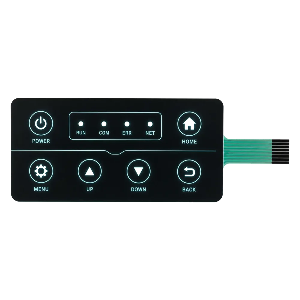
A backlit membrane switch can pass its electrical test and still look wrong. LED hot spots, glowing edges, weak dead-front concealment, washed-out legends, or uneven icons appear only when the light source, printed overlay, spacer, circuit and enclosure are reviewed together.
This page follows an anonymous project type from lighting intent through lit and unlit sample approval. It does not present a named customer or a measured field result.
What this example does and does not claim
The project frame reflects common OEM optical, printing and electrical reviews. It does not identify a customer, equipment program or approved brightness value, and it does not claim a lifetime, protection rating, production quantity, delivery time or field result. Those values require a defined construction, viewing method and project record.
Project frame
The useful starting point is the visual task, not a preferred lamp or a finished artwork file. These five points define the first engineering conversation.
Electrical function does not approve the optical result
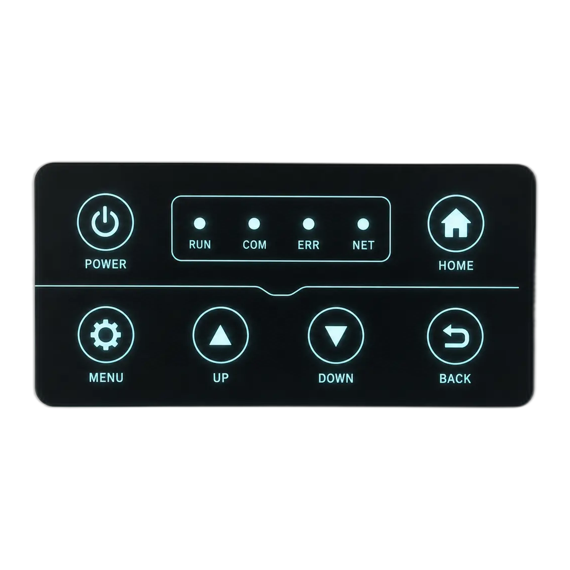
A circuit tester can confirm polarity, continuity and the intended LED connection. It cannot decide whether the POWER icon looks even, whether the unlit NET symbol disappears as intended, or whether light escapes through a printed border.
The front appearance is created by a path. Source position, cavity, reflector, diffuser or light-guide film, spacer thickness, adhesive openings, translucent ink, opaque mask and surface texture all change what reaches the user's eye.
The enclosure changes that path again. Internal walls can block or reflect light, a mounting recess can compress the stack, and a nearby display or indicator can contaminate an optical zone. The sample therefore has to be powered in representative hardware and viewed under agreed conditions.
What had to be reviewed as one light path
Most visible defects appear at the boundary between two layers or disciplines. These five decisions cannot be approved independently.
Lighting task and source
A status point, a complete legend and a broad key zone need different source placement, drive conditions and light-management structures.
Artwork, mask and dead-front effect
Translucent color, opaque backing, icon edges and surrounding black determine both off-state concealment and on-state contrast.
Diffusion and uniformity
Diffuser, reflector, cavity and light-guide choices control source visibility, bright centers, dim corners and spill into adjacent symbols.
Circuit routing and stack thickness
LED pads, conductive traces, switch contacts, domes, spacers and tail routing compete for the same limited panel area and height.
Enclosure and viewing condition
Mounting support, internal walls, surface angle, ambient light and observer position can change a panel that looked acceptable on the bench.
Approve the interface as a sequence of visible states
A single powered photograph hides too much. The review should move through the states the user will actually see and record a decision for each one.
Off state
Inspect the unpowered face before judging brightness
Check whether inactive icons are hidden or intentionally visible, whether masking looks solid, and whether windows, edges, adhesive openings or internal parts show through.
Normal ambient
Confirm printed legends remain readable without relying on light
Review glare, surface texture, color contrast and viewing angle in the equipment's normal environment. Illumination should not compensate for weak base graphics.
Powered state
Look for uniformity, hot spots and optical cross-talk
Power the specified zones and inspect icon edges, centers, neighboring graphics, color balance and source visibility from the normal operating position.
State change
Check that the visual message changes as intended
Cycle the relevant modes, alarms or indicators. The difference between inactive and active states should be clear without creating an unintended halo or competing signal.
The first sample had to answer four practical lighting questions
These questions turn a general request for backlighting into conditions that can be checked on a physical panel.
Is the light showing status, identifying a control or illuminating a wider work area?
Separate point indicators from illuminated legends and key zones. Each function may need a different opening, source position, diffusion method and acceptance rule.
What should the user see when the panel is not powered?
Mark icons that should disappear, remain faint or stay fully printed. The masking and color stack can then be reviewed against an explicit off-state target.
Where can the light source sit without creating a visible center or dark edge?
Review the source, cavity, reflector, diffuser or light guide together with icon size, spacing and nearby switch features.
Does the enclosure preserve the intended light path?
Install the panel on representative support and check recesses, internal walls, compression, nearby displays, cable routing and reflective surfaces.
What the buyer should approve during sampling
The approved reference needs a viewing setup as well as a part number. Otherwise two people can look at the same panel under different light and reach different conclusions.
Inspect the unpowered panel in the agreed ambient condition
Review dead-front concealment, printed color, gloss, icon edges, windows, surface marks and any unintended visibility through the front.
Power each required zone with the intended electrical condition
Confirm source color, zone mapping, polarity, active combinations and the difference between normal, warning and inactive states.
View the installed panel from the real operating position
Check bright centers, dim corners, edge leakage, neighboring-icon glow, reflections and legibility at the expected distance and angle.
Release a controlled optical reference
Tie the accepted sample to the current artwork, print stack, circuit, source, diffuser or light guide, enclosure setup and written inspection notes.
Production controls that protect the approved light state
Optical appearance depends on repeatable print density, registration, layer alignment and electrical assembly. A small shift can be visible even when every circuit still passes.

Printing and visual control
Masking, translucent color and icon registration must stay together
Opaque areas contain the light while translucent areas shape the visible symbol. Printing and lamination checks should compare icon edges, color, surface condition and layer registration with the released reference.
- Artwork revision, mask openings and translucent colors checked before release
- Printed opacity, icon edges and layer registration reviewed during production
- Unpowered appearance compared with the approved visual reference

Electrical and powered inspection
Circuit checks and illuminated appearance need separate pass criteria
Electrical testing verifies the connection, polarity and switch circuit. A powered visual check then confirms zone mapping, source operation and the appearance of the required lit states.
- Continuity, open, short, polarity and zone mapping checked to the released circuit
- Specified lighting combinations powered for visual review
- Panel, tail, connector and lit-state records linked to the same revision
What to send before the optical stack is fixed
A simple state drawing and a photograph of the installation environment can prevent more rework than a finished front artwork with no lighting context.
Icons, legends, windows, translucent zones, opaque masks and what should be visible when each light is off or on
Status indication, key identification, broad illumination, dead-front reveal, source color and required active combinations
Ambient light, viewing distance, surface angle, observer position, glare concerns and whether day and night use differ
Available voltage, current or driver constraints, connector, polarity, circuit interface, control method and duty pattern
Panel outline, target thickness, switch features, source location, diffuser or light-guide space, adhesive and enclosure support
Representative enclosure, powered states, comparison reference, viewing setup, cosmetic priorities and required records
Continue the review with the underlying technical pages
This case connects optical appearance with the membrane switch construction. These pages cover the lighting, circuit, overlay and engineering decisions behind it.
Questions that usually come up before a similar RFQ
Can JASPER manufacture backlit membrane switches with LED indicators?
JASPER can manufacture custom backlit membrane switches and control panels when the lighting task, artwork, source, circuit, stack, enclosure and inspection method are defined. The final equipment-level validation remains part of the buyer's project.
What causes hot spots or light leakage in a backlit panel?
Visible hot spots or leakage can come from source position, cavity shape, insufficient diffusion, mask openings, print opacity, spacer gaps, adhesive openings, layer misalignment or enclosure reflections. The exact cause should be checked on the installed stack.
Can an icon remain hidden until it is illuminated?
A dead-front effect can be designed, but the off-state and on-state must be approved together. Overlay material, surface finish, color, translucent ink, opaque backing and ambient light all affect the result.
Should electrical testing and optical inspection use the same criteria?
No. Electrical testing confirms connection, polarity and circuit behavior. Optical inspection evaluates concealment, uniformity, contrast, leakage, color and readability under an agreed viewing setup.
What is the minimum information needed for a first backlighting review?
Send the panel artwork or sketch, intended lit and unlit states, source color, electrical limits, panel and enclosure geometry, viewing environment and the appearance conditions that matter during sample approval.
Approve the message the light creates, not only the lamp
Send the artwork by state, viewing condition, electrical limits, source preference, stack constraints and enclosure drawing. JASPER can review the open optical and integration decisions before they become tooling or powered-sample changes.