
Membrane keypad vs silicone keypad is a construction decision, not a contest with one universal winner. Choose a membrane keypad when a low-profile, continuous graphic surface and integrated flexible circuit or tail dominate. Choose a silicone keypad when raised three-dimensional keys, touch localization, molded web travel, or a captured elastomer feature governs the enclosure. This comparison is for OEM engineering, quality, and sourcing teams choosing an architecture before tooling. Its boundary is the installed HMI—not a loose rubber mat versus a finished membrane switch. Either route can provide tactile feedback, lighting, and an enclosure seal, but only when the actuator, circuit, housing, venting, graphics, and validation plan are defined together.
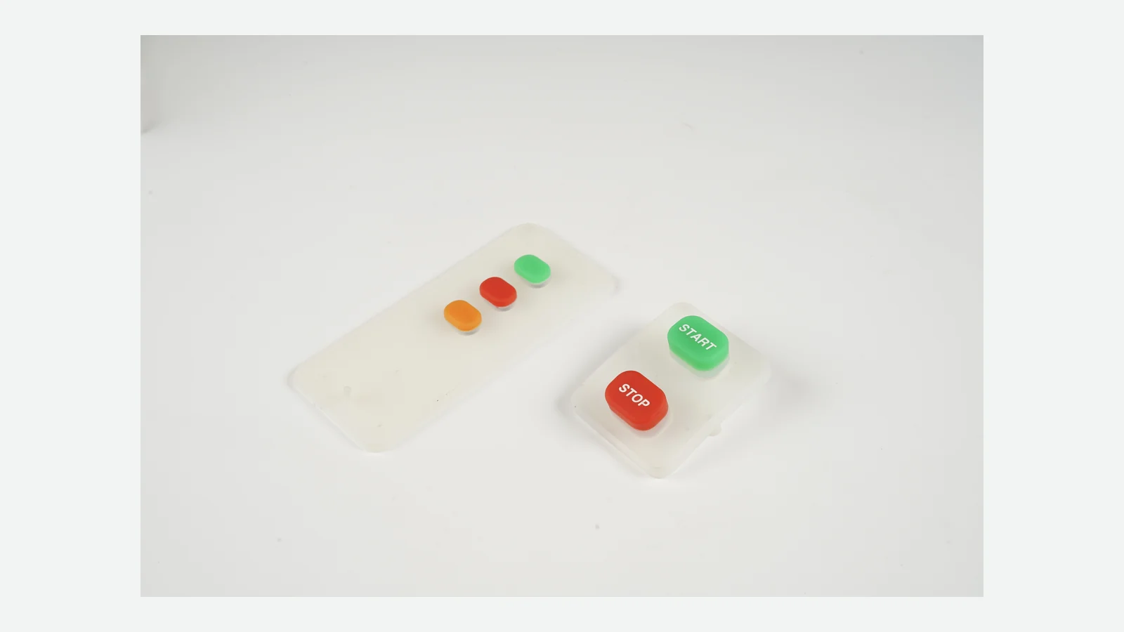
Membrane Keypad vs Silicone Keypad: Quick Decision Table
The quickest defensible choice follows the governing constraint. Read this rubber keypad comparison by condition, not by counting check marks: a mandatory requirement can outweigh several minor conveniences.
| Governing requirement | Membrane keypad tends to fit | Silicone keypad tends to fit | Decision boundary |
|---|---|---|---|
| Minimum front-stack depth and a planar face | ✓ | Confirm the complete installed stack; carriers, light guides, components, and bezels can erase the advantage | |
| Raised, sculpted, guarded, concave, or grouped keys | ✓ | Approve key wobble, edge presses, bezel clearance, and housing support | |
| One continuous reverse-printed graphic surface | ✓ | Validate the selected film, ink, hard coat, adhesive, and cleaning agents | |
| Integrated printed circuit and flexible tail | ✓ | Confirm current, routing, connector, bend, shielding, and support requirements | |
| Molded web response and positive touch location | ✓ | Specify force, travel, snap, return, sound, and off-axis behavior separately | |
| Frequent language, brand, or model artwork variants | ✓ | This holds only when key centers, circuit, windows, and housing remain common | |
| A replaceable keymat over an existing PCB | ✓ | Capture and service strategy must preserve alignment, contact, and sealing compression | |
| Crisp metal-dome snap | Either route can use a metal dome; evaluate it in the final overlay/actuator/support stack | ||
| Finished-enclosure ingress target | No default winner: IEC 60529 applies to the tested enclosure or enclosing part, not the keypad material | ||
| Raised keys plus a thin printed circuit or dome layer | Consider a hybrid, then account for its added interfaces, tolerance stack, venting, and assembly controls |
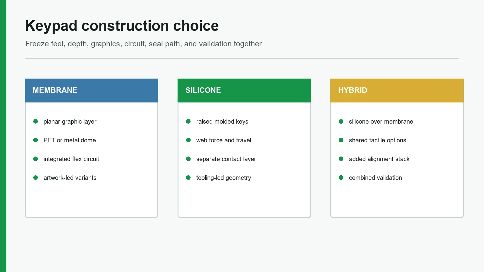
The practical split is geometry. Geometry decides. A membrane construction trades molded depth for a laminated interface and integrated circuit. Silicone uses more physical shape to create finger location, travel, web behavior, and possible sealing features. Neither statement is a performance guarantee.
What Each Keypad Construction Actually Includes
A fair silicone keypad vs membrane switch comparison uses complete-system boundaries. A keymat is not automatically a circuit; a membrane switch is not automatically a supported, sealed panel.
Membrane keypad construction
A membrane-switch construction includes polyester circuit sheets, printed conductors, spacers, a dome retainer, PET/PC graphics, mounting material, and a flex tail. Switching may be non-tactile, a formed PET polydome, or a metal dome.
The laminate can integrate circuit and tail. The OEM must still specify support, tail path, connector, retention, housing cutout, lighting, and shielding; see the membrane switch layer stack.
Silicone keypad construction
A silicone keypad molds keytops, webs, a base mat, locating features, and often a perimeter. It may carry carbon or metal contacts or actuate a dome, tactile switch, membrane circuit, PCB, or FPC.
The part still needs PCB support, aligned contact pads, stops, bezel clearance, and controlled housing compression. Put the circuit boundary on the drawing and supplier responsibility matrix.
The hybrid construction
Hybrid construction places raised silicone over a membrane circuit or metal dome when touch location and printed circuitry or a tail are both needed. It adds alignment, stack-height, venting, tolerance, assembly, and ownership risks.
MEMBRANE KEYPAD
finger
graphic overlay → overlay adhesive / emboss
optional dome or printed contact → spacer / vent path
printed PET circuit or FPC → flex tail / connector
rear adhesive or frame → support panel / enclosure
SILICONE KEYPAD
finger
molded keytop / legend → web / guide / stop
conductive contact or separate actuator
PCB, FPC, membrane circuit, dome, or tactile switch
support structure → captured perimeter / enclosure
HYBRID
silicone key and web
metal dome or membrane contact layer
printed circuit / tail
shared support, vent, seal, and housing stack
Travel, Feel, Thickness, and Geometry Must Be Specified Separately
Neither construction owns tactile quality. The operator feels a force-displacement system made from the key or overlay, actuator, circuit contact, support, housing, and any mechanical stop—not a material name.
For silicone, specify actuation, contact, and return forces, travel, and snap. The complete force-travel curve must retain return margin under web, preload, and stop conditions.
ASTM D2240 and ISO 48-4 define Shore durometer methods; hardness alone does not define feel. Web geometry, key area, travel, contacts, and enclosure compression can differentiate compounds with the same Shore A result.
For membrane keypads, identify non-tactile, PET-dome, or metal-dome action and test it under the production overlay, retainer, emboss, spacer, actuator, and support; test the actual production stack.
| Design question | Membrane keypad evidence | Silicone keypad evidence | Omission risk |
|---|---|---|---|
| Can users locate and press keys under declared glove and surface states? | Emboss, spacing, texture, bezel guards; installed-state test | Molded height, form, grouping, guards; return after conditioning | Adjacent inputs or task failure |
| What does one press feel like? | Installed curve with production overlay and dome/contact | Installed actuation, contact, return, travel, and snap | Post-assembly feel mismatch |
| What happens on an edge press? | Emboss/dome alignment and panel support | Wobble, guides, stops, web loading, and contact overlap | Intermittent closure, rubbing, or jamming |
| How much Z-space is available? | Overlay, dome/spacer, circuit, adhesive, lighting, parts, and panel | Key, web travel, stop, contact, PCB/switch, support, and capture | Redesign or lost travel |
Membrane usually fits a planar, tight Z-envelope; silicone usually fits three-dimensional touch landmarks. Compare the installed stack because carriers, light guides, components, stops, and shared housing features can reverse a catalog-level expectation.
Sealing and Venting: Neither Keypad Owns the IP Rating
Ingress performance belongs to the tested enclosure or enclosing part. IEC 60529 classifies enclosure protection against access, solid foreign objects, and harmful water ingress; it does not assign an IP code to silicone, PET, adhesive, or a loose keypad.
A silicone design can mold a perimeter lip or gasket land that the housing compresses. That creates a useful sealing feature, but it also couples sealing compression to keypad fit and sometimes to key feel. The drawing must control the compression land, fastener pattern, mating-surface flatness, locating scheme, vent paths, and the relationship between the keymat and PCB. Excess preload can consume travel or distort the web; too little or uneven compression can leave a leak path.
A membrane design can use a continuous overlay and perimeter adhesive over a controlled panel. The seal still depends on edge distance, panel material and finish, cutouts, fasteners, tail exit, surface preparation, adhesive width, pressure, dwell, and environmental aging. Adhesive selection must follow the actual substrate and surface energy; no single adhesive family is a universal default.
Both routes may need air movement beneath a key or dome. The vent must allow the intended actuation without crossing the sealed perimeter or connecting a contaminated cavity to protected electronics. Sealed silicone layouts can use controlled air ducts, while metal-dome evaluation must include the vent path.
Specify the target IP code, test orientation, installed enclosure, cable or tail state, fastener torque, preconditioning, and pass criteria. Test the enclosure. If the product sees humidity, distinguish non-condensing steady damp heat from cyclic conditions that produce condensation: IEC publishes separate methods in IEC 60068-2-78:2025 and IEC 60068-2-30:2025. A material coupon or loose keypad cannot close this system-level decision.
Graphics and Backlighting Favor Different Change Patterns
Membrane construction usually makes printed information easier to separate from three-dimensional key geometry. Silicone makes the key shape part of the industrial design, but decoration and lighting can become more coupled to coatings, molded color, and the PCB.
A membrane graphic overlay is commonly printed on its back, or second surface, so the film sits between the operator and the ink. Both polyester and polycarbonate are used; selection depends on forming, actuation, appearance, coatings, and environment. A language or brand change may therefore stay in the artwork layer if the switch centers, circuit, windows, and housing do not move. It still requires controlled color, registration, print setup, inspection, inventory, and any necessary revalidation.
Silicone legends may be printed on suitable keytops or made with a coated-and-laser-opened construction. A coated and laser-opened keypad construction combines molded silicone, color and dark coatings, laser opening, and a protective overcoat. That example proves the process route exists; it does not prove that a laser-opened legend is wear-proof or that JASPER uses the same stack. The production keypad must be checked with its actual cleaner, contact pattern, coating edges, key geometry, and use zone.
Backlighting must be approved as a complete optical chain.
Membrane backlighting can use side-view LEDs, light-guide film, diffusers, and extraction features. Silicone backlighting depends on compound color/translucency, LED position, masks, and light-blocking geometry. Neither route is inherently uniform. Approve unlit appearance, day and night readability, hot spots, leakage between keys, color, window clarity, and current draw in the final housing.
Where a registered equipment symbol applies, control its reference and artwork. ISO 7000 and the IEC 60417 database cover different graphical-symbol scopes. Using a registered symbol is an artwork decision, not product certification.
Tooling, Circuit, Assembly, and Change Exposure
Both constructions create non-recurring work. The difference is what becomes expensive or slow to change after release, not whether “tooling” exists.
Silicone tooling fixes keytops, webs, base, contacts, locators, and perimeter geometry. A geometry change can reach the housing, PCB, optics, force curve, and seal compression; decoration and inspection tools may also change.
Membrane release assets can include artwork, print/cut programs, spacers, dome layouts, lamination fixtures, circuit tests, and masters. Artwork-only variants may retain the circuit and housing; moving a key can change every layer and firmware.
| Expected change | Silicone exposure | Membrane exposure | Architecture implication |
|---|---|---|---|
| Legend, language, or brand only | Printing/coating/laser artwork, inspection, inventory; mold may remain common | Overlay artwork, print setup, inspection, inventory; circuit may remain common | Membrane often separates artwork variants more cleanly, provided geometry stays fixed |
| Key position, height, guard, or shape | Mold, housing, contact alignment, feel, lighting | Overlay, emboss/dome, spacer, circuit, panel, support | High-impact change in either route; freeze before tooling |
| Circuit map, tail, or connector | PCB/FPC/contact interface and possibly housing | Printed circuit, tail, connector, spacer and test fixture | Compare the same electrical deliverable, not a keymat against a terminated switch |
| Backlight state or legend opacity | Compound/color/coating/laser stack, LED PCB, masks | Overlay masks/windows, light guide, LED circuit, spacers | Powered installed samples are required for both |
| Seal path or enclosure fasteners | Molded lip/capture, compression, locating, vents | Perimeter bond, panel finish, edge distance, tail exit | A housing revision can invalidate prior ingress evidence |
| Field-replaceable unit | Keymat, PCB, carrier, or module boundary | Bonded switch, panel, tail, or module boundary | Serviceability follows attachment and partitioning, not the technology name |
Compare equal supplied boundaries: loose keymat versus bare laminate, or complete module versus complete module. Assign one owner for preparation, alignment, capture/lamination, contact placement, tail/connector, fasteners, optical/electrical/ingress tests, and packaging.
Lifecycle Claims Need a Test Definition, Not a Brochure Number
No keypad life is universal. Define the production stack, actuator, force/over-travel, cycling rate, electrical load, environment, samples, measurements, and failure criteria.
ASTM F1578-24 defines cycling of a membrane switch to a predetermined count, optionally at specified voltage and current, while checking contact reliability, damage, and before/during/after measurements. It sets no universal cycle requirement and does not qualify silicone or a finished HMI.
Silicone needs a project-specific installed fixture and operating profile. ASTM D395 evaluates rubber after prolonged static compression, not repeated key action; compression-set results cannot be converted into key cycles or service years.
The listed risks remain open when force, sealing, venting, adhesive, lighting, or lifecycle criteria are approved outside the installed stack. The matrix below ties each risk to production-intent evidence.
Minimum validation matrix
The OEM must set severity from actual use; these standards define methods or scope, not project pass values.
| Risk | Specimen / method | Define | Acceptance |
|---|---|---|---|
| User feel and false actuation | Installed keypad, support, housing, stop, and declared glove; force-displacement, off-axis, and repeat testing | Force/contact/return points, travel, location, rate, temperature | Project window, full return, no adjacent input |
| Electrical contact and cycling | Actual circuit, contact finish, connector, and load; ASTM F1578-24 for membrane, installed fixture for silicone | Count, rate, voltage/current, duty, over-travel, environment, samples | Resistance/contact limits, no intermittency, permitted drift and damage |
| Enclosure ingress | Complete enclosure with production seals, fasteners, tail/cable, vents, and openings; IEC 60529 | IP code, orientation, torque, preconditioning, test state | No harmful ingress and required post-test function |
| Temperature change | Complete assembly; IEC 60068-2-14:2023 | Limits, dwell/rate, cycles, powered state, recovery | Contact, force/return, bond, optics, and function |
| Humidity / condensation | Complete assembly; IEC 60068-2-78:2025 or IEC 60068-2-30:2025 | Method, temperature/RH, duration, power, recovery | No unintended input, corrosion, delamination, or functional drift |
| Vibration and shock | Installed module with restrained connector/tail; IEC 60068-2-6:2007 and IEC 60068-2-27:2008 | Axes, severity, duration/pulses, mounting, monitoring | No chatter, damage, loosening, or functional drift |
| Rubber material and molded fit | Cured compound and tooled parts; ASTM D2240, ASTM D395, ISO 3302-1 / ISO 3302-2 | Grade, conditioning, tolerance class, controlled dimensions | Drawing/material limits; not a substitute for finished-key life |
| Graphics, cleaners, and optics | Decorated installed parts; actual fluids and controlled visual/optical inspection | Fluid, dose, cycles, recovery, illumination | Legibility, adhesion, contrast, leakage, and function |
For medical equipment, component evidence is not finished-device approval. The FDA Quality Management System Regulation applies to finished-device manufacturers, while FDA biocompatibility assessment evaluates final form and component interactions. Keypad material reports and sample approval do not replace finished-device validation.
Decision Matrix: When Each Construction Is Not the Best Choice
The right keypad construction choice is the route that removes the highest-risk interface without violating a must-have requirement. Do not average away a disqualifier.
| Project condition | Preferred starting point | Why | When that recommendation fails |
|---|---|---|---|
| Very limited front-stack depth; flat face required | Membrane keypad | Laminated graphic and circuit layers support a planar interface | A carrier, light guide, components, or bezel consumes the expected Z-space |
| Raised keys must be located by touch or through gloves | Silicone keypad | Molded shapes, height, grouping, and guards can form the navigation surface | Key wobble, clearance, force, or return cannot be stabilized in the housing |
| Many language or brand variants share one key map | Membrane keypad | Artwork can often vary while geometry and circuit stay common | Windows, key centers, circuits, or compliance markings change with the variant |
| Existing PCB should accept a separately serviceable keymat | Silicone keypad | The molded part can be captured above the contacts | Adhesive, overmolding, or destructive enclosure joints make it non-serviceable |
| Continuous wipe-down face is the governing user need | Membrane keypad | A flat overlay can reduce exposed crevices | The selected film, ink, hard coat, bond, or edge cannot withstand the actual cleaning process |
| Enclosure concept depends on a molded compression feature | Silicone keypad | A lip or gasket land can be integrated into the molded geometry | Compression tolerance changes key feel or the assembled enclosure misses its ingress criteria |
| Raised keys and metal-dome snap are both mandatory | Hybrid | Silicone can actuate a dome over a membrane circuit or PCB | Added stack, venting, alignment, and assembly ownership create more risk than the benefit resolves |
Silicone is not the best choice when the product must remain flat, model differentiation is mainly printed artwork, or the team cannot freeze molded geometry before tool release. Membrane is not the best choice when the operator needs unmistakable raised landmarks, deep sculpted geometry, or a separately captured elastomer part and the enclosure has room for it. A hybrid is not the best choice when the organization cannot control its extra interfaces.
Freeze the Input Package Before Tooling
Architecture approval should close the system boundary before mold, print, cutting, spacer, dome, circuit, or inspection tooling is released. Use the same input package for both routes.
| Drawing or approval field | Minimum content |
|---|---|
| Operator and use | Bare finger or named glove, posture, viewing direction, eyes-off needs, wet/dirty states, adjacent-key risk, press rate |
| Mechanical envelope | 2D drawing and 3D model, datums, total Z-envelope, key/actuator centers, support, hard stops, bezel, fasteners, service path |
| Feel | Actuation/contact/return targets, travel, snap behavior, sound, off-axis locations, installed measurement method |
| Electrical | Contact architecture, PCB/FPC/PET boundary, pad finish, key map, voltage/current, tail, connector, grounding/shielding, monitoring criteria |
| Seal and vent | Target IP code, tested enclosure state, compression/bond land, vent route, tail/cable exit, panel finish, torque, preconditioning |
| Graphics and light | Controlled artwork, symbol references, languages, color/texture, print or coating stack, LEDs/drive, masks, day/night approval states |
| Environment and life | Operating/storage profile, actual cleaners and oils, condensation, shock/vibration/salt exposure, cycle profile, sample count, failures |
| Supply and change boundary | Loose part versus module, supplied components, assembly/test owners, tooling ownership, records, change notice, service spare |
Use production-intent prototyping to answer a stated question at each sample stage. An appearance model can close layout and touch location; it cannot prove production force, coating life, ingress, or cycling. A tooled and installed sample can close more risks, but only under defined conditioning and acceptance criteria. Teams working on industrial control panel interfaces should include the real glove, mounting panel, connector restraint, lighting state, and cleaning exposure.
The concrete next step is simple: choose the construction before tooling, then freeze one controlled drawing and validation matrix. If the remaining unknowns could still reverse the choice, request a documented keypad architecture engineering review before releasing either route.
Frequently Asked Questions
Which is better in a membrane keypad vs silicone keypad decision?
Neither. Start with installed Z-space, operator task, artwork changes, circuit boundary, sealing, and validation. Membrane favors thin planar graphics; silicone favors raised touch geometry.
Is a silicone keypad always thicker than a membrane keypad?
Usually, but compare the complete assembly. Membrane carriers, light guides, and bezels add depth; silicone may share the existing PCB and housing.
Which construction gives better tactile feedback?
Neither by default. Compare the installed force-displacement curve: membrane may use PET or metal domes; silicone may use web collapse or actuate a dome.
In a silicone keypad vs membrane switch, which is easier to seal?
Neither. Silicone offers molded seal lands; membrane offers a continuous overlay and perimeter bond. IEC 60529 rates the complete enclosure, including openings and fasteners.
Is a membrane keypad cheaper because it does not need a mold?
No. Membrane still needs print/cut programs, spacers, dome or lamination fixtures, tests, and inspection masters. Compare equivalent supplied boundaries and revision exposure.
Can a silicone keypad use a membrane circuit?
Yes. Silicone can actuate a membrane circuit or metal dome, but the hybrid adds alignment, stack, venting, compression, connector, and assembly controls.
How should keypad lifecycle be specified?
Define construction, actuator, force/over-travel, rate, load, environment, samples, measurements, and failures. ASTM F1578-24 supplies a membrane cycling method, not a universal minimum.
What information is required before keypad tooling is released?
Release controlled operator, geometry, force/travel, electrical, seal/vent, graphics/light, environment/life, supplied-boundary, acceptance, and change-control inputs.
Technical References
- Source: Molex membrane switch construction technical guide. Accessed 2026.
- Source: Shin-Etsu keypad contact element and force-travel guidance. Accessed 2026.
- Source: ASTM D2240 rubber durometer hardness test method. Accessed 2026.
- Source: ISO 48-4 rubber durometer hardness test method. Accessed 2026.
- Source: ASTM D395 rubber compression set test method. Accessed 2026.
- Source: ISO 815-1 rubber compression set test method. Accessed 2026.
- Source: ISO 3302-1 rubber dimensional tolerance standard. Accessed 2026.
- Source: ISO 3302-2 rubber geometrical tolerance standard. Accessed 2026.
- Source: ASTM F1578 membrane switch contact closure cycling practice. Accessed 2026.
- Source: IEC 60529 enclosure protection classification. Accessed 2026.
- Source: IEC 60068-2-14 temperature change testing. Accessed 2026.
- Source: IEC 60068-2-30 cyclic damp heat testing. Accessed 2026.
- Source: IEC 60068-2-78 steady damp heat testing. Accessed 2026.
- Source: IEC 60068-2-6 sinusoidal vibration testing. Accessed 2026.
- Source: IEC 60068-2-27 shock testing. Accessed 2026.
- Source: ISO 7000 graphical symbols for equipment. Accessed 2026.
- Source: IEC 60417 graphical symbols for equipment. Accessed 2026.
- Source: FDA Quality Management System Regulation. Accessed 2026.
- Source: Molex membrane-switch construction. Accessed 2026.
- Source: Mekoprint guide. Accessed 2026.
- Source: Shin-Etsu. Accessed 2026.
- Source: N&H guide. Accessed 2026.
- Source: ASTM D2240. Accessed 2026.
- Source: ISO 48-4. Accessed 2026.
- Source: Snaptron. Accessed 2026.
- Source: IEC 60529. Accessed 2026.
- Source: 3M's low-surface-energy bonding paper. Accessed 2026.
- Source: dome test procedure. Accessed 2026.
Freeze the keypad construction before tooling
Send the operator task, Z-space, force and travel targets, circuit boundary, seal path, artwork, lighting, quantities, and approval tests.