Dongguan, Guangdong 523927, China[email protected]+86 136 3262 5290
Home / Products / Medical Electrode Pads / Custom EEG Electrode Arrays
MULTI-SITE FLEXIBLE ARRAYS FOR OEM NEUROPHYSIOLOGY HARDWARE

Custom EEG Electrode Arrays

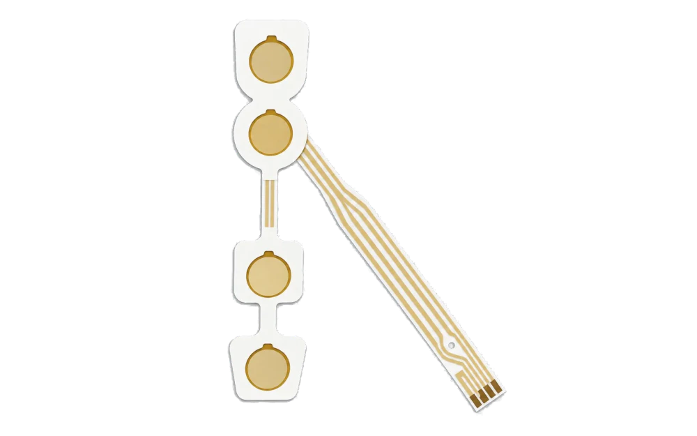
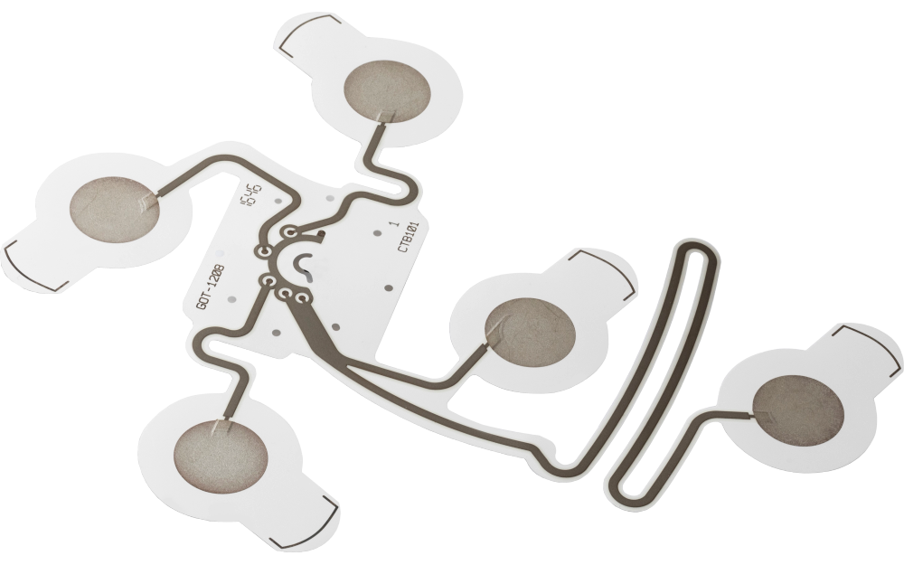
Flexible custom EEG electrode array with eight printed sites and routed tail

A custom EEG electrode array turns an OEM site map into one registered flexible circuit. JASPER can print the electrode sites, channel traces, reference or ground positions, dielectric zones, tail and connector lands, then convert project-specified backing, adhesive or hydrogel zones, reinforcement, liner, labels, and packaging. Placement, acquisition electronics, signal interpretation, patient use, and regulatory validation remain with the OEM.

Flexible custom EEG electrode array with eight printed sites and routed tail
Multi-site geometrychannel positions, reference sites, routing, dielectric, datums, and orientation
Flexible handoffsubstrate, tail, reinforcement, connector, cable relationship, and strain control
OEM system validationplacement, acquisition hardware, algorithms, clinical use, and regulatory pathway retained

An EEG Array Must Preserve Site Identity from Contact Area to Connector

The outside shape is only a carrier. The manufacturing master must identify every active site, channel name, reference or ground position, conductive route, dielectric opening, crossing rule, tail conductor, connector land, and registration feature.

A flexible array can simplify placement and wiring, but it does not define acceptable physiological signal performance. The OEM must release electrical acceptance and validate the array with its placement method, cable, acquisition electronics, software, and intended use.

Custom EEG Electrode Arrays fit when:

  • several electrode sites must remain positioned and channel-identified on one flexible carrier
  • printed routing, dielectric coverage, tail conductors, and connector lands require one circuit master
  • converted layers and placement features can be registered to the same array datums
  • the OEM owns placement, signal-chain, algorithm, clinical, biocompatibility, and finished-device validation

Six Controls Preserve EEG Site Geometry and Channel Identity

Every channel must remain traceable from the contact opening through the flexible tail.

01

Site map and orientation

Release control

Release coordinates, spacing, array orientation, anatomical references, active, reference and ground sites, and placement datums.

If it is missing

The array fits physically but places a channel or reference site in the wrong location.

02

Channel routing

Release control

Define channel names, trace paths, widths, clearances, crossovers, guards, dielectric, continuity, resistance, and isolation.

If it is missing

Channel identity or electrical separation is lost between the site map and connector.

03

Contact opening and material zones

Release control

Map printed contact, insulation opening, adhesive or hydrogel zone, backing, liner, and non-contact areas at every site.

If it is missing

Converted layers reduce or shift the intended exposed contact geometry.

04

Tail and connector

Release control

Release conductor pitch, tail outline, bend zone, reinforcement, connector, cable, pin map, keying, and mating part.

If it is missing

The array cannot connect or route without stressing conductors or changing channel order.

05

Registration and placement features

Release control

Control holes, slots, fiducials, edge datums, split lines, stretch limits, labels, and placement fixture references.

If it is missing

Sites shift relative to the OEM placement method during assembly or use preparation.

06

Inspection and traceability

Release control

Define site position, channel continuity, resistance method, isolation, connector map, visual defects, label, lot, and packaging.

If it is missing

A channel defect or revision mismatch cannot be isolated after the array is packaged.

Release Every EEG Channel from Site to Mating Interface

The specification should let manufacturing and the OEM test the same channel map without interpretation.

BoundaryOptions to ReviewRelease Question
Array geometrySite coordinates, spacing, active, reference and ground sites, orientation, landmarks, placement holes, and flexible zonesWhat geometry must the converted array preserve?
Printed circuitInk, substrate, traces, clearances, dielectric, contact openings, guards, resistance, continuity, and isolationWhich electrical criteria apply per channel and between channels?
Tail and connectorTail width, pitch, reinforcement, bend radius, connector, pin map, cable, keying, retention, and mating partHow is channel identity preserved at the OEM interface?
Converted stackBacking, adhesive or hydrogel zones, foam or nonwoven, site openings, liner, labels, and handling tabsWhich layers are included and how are they registered?
Placement featuresFiducials, holes, slots, split lines, edge datums, orientation marks, stretch limits, and fixture featuresHow will the OEM position the array repeatably?
Evidence and packagingDimensions, site position, channel map, resistance, continuity, isolation, connector check, label, pack, and traceabilityWhich evidence accompanies first articles and repeat lots?
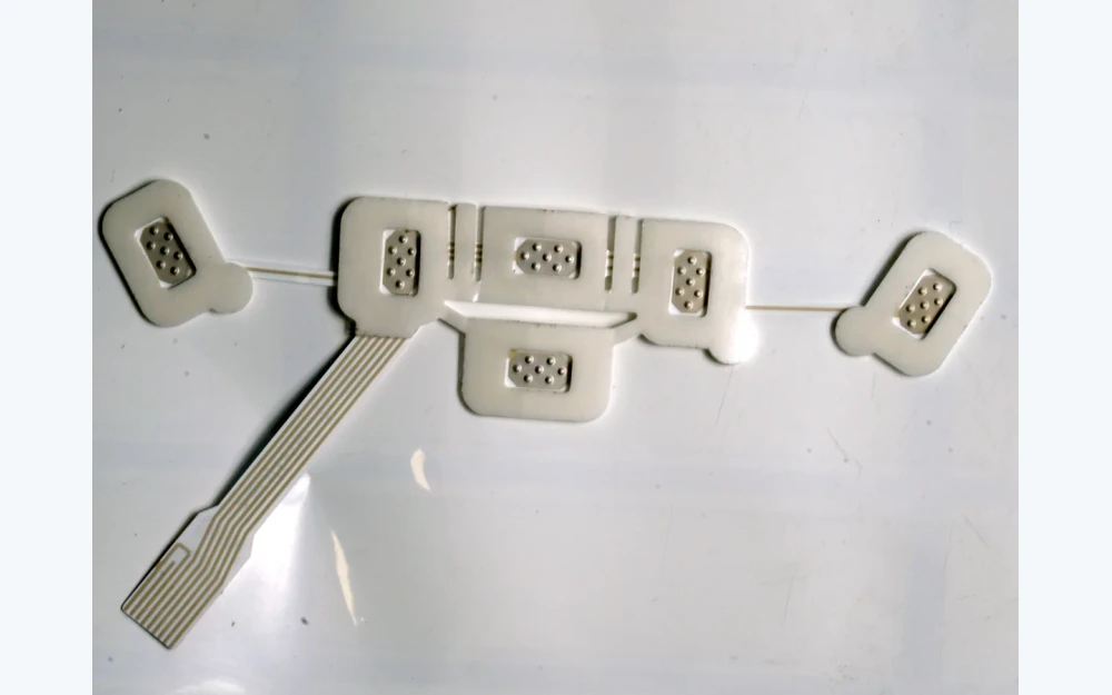
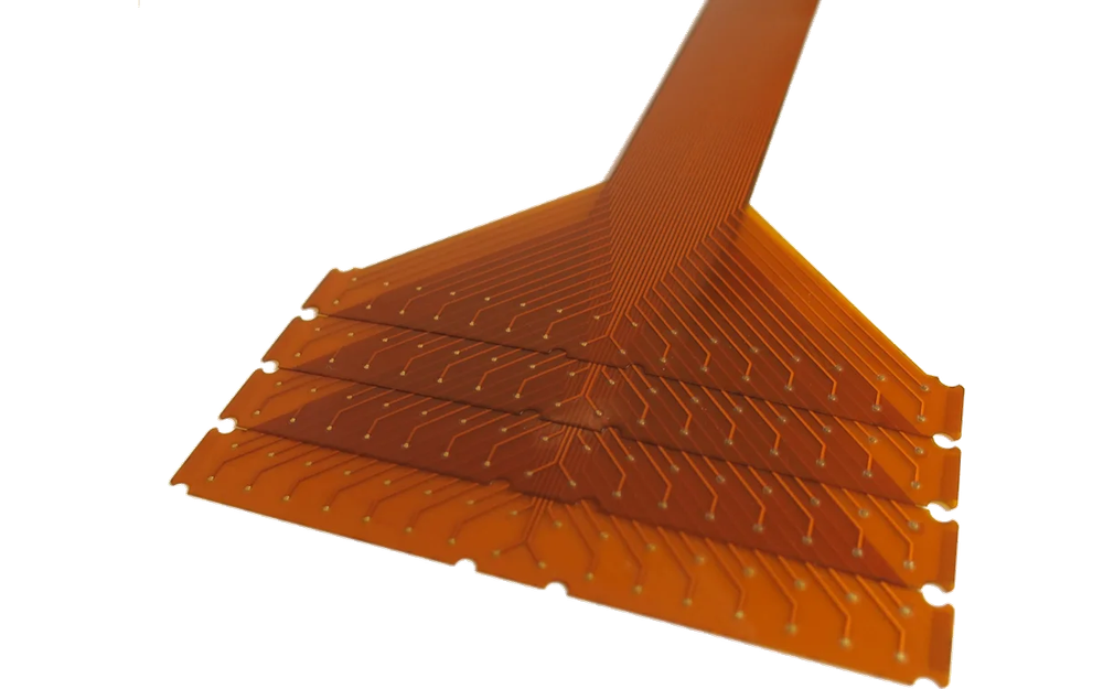
Printed multi-channel EEG electrode array with routed traces and flexible tail
CHANNEL ROUTING

Make the Printed Artwork the Single Channel-Identity Master

Site labels in a drawing, conductor order in a tail, and connector pin numbers must describe the same map. The circuit master should expose any shared reference, guarded region, dielectric crossing, bend zone, or routing density that affects print and inspection.

  • name every active, reference, and ground site
  • release trace and dielectric geometry as controlled vector data
  • define channel-specific continuity, resistance, and isolation checks
  • retain pin map and circuit artwork under the same revision
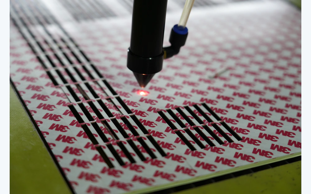
Layer and die-cut registration model for a flexible EEG electrode array
ARRAY REGISTRATION

Register Site Openings, Flexible Layers, and Placement Features

The conductive pattern can be correct while the converted array is wrong. Site openings, adhesive zones, backing, liner, holes, slots, labels, and outside profile must be dimensioned from array datums that the placement method can also use.

  • separate circuit tolerance from converting tolerance
  • identify stretch-sensitive and bend-sensitive regions
  • inspect critical site positions with a fixture or vision method
  • approve production packaging that protects the array geometry

Move from Printed Geometry to a Controlled OEM Handoff

01

Release the site map

Define active, reference and ground sites, coordinates, orientation, placement features, and OEM validation.

02

Route and identify channels

Close traces, clearances, dielectric, tail order, connector pin map, and electrical acceptance.

03

Build the converted stack

Release substrate, contact openings, backing, adhesive or hydrogel zones, liner, labels, and reinforcement.

04

Approve array samples

Review site position, channel map, electrical checks, connector, flexibility, registration, handling, and packaging.

05

Control repeat lots

Lock artwork, materials, connector, fixtures, records, packaging, substitutions, and requalification triggers.

Trace EEG Array Issues from Site Map to OEM Interface

01

Channel order is wrong

Compare site labels, circuit artwork, tail conductors, connector pin map, cable, inspection fixture, and revision.

02

Sites shift after converting

Review substrate stability, adhesive or hydrogel zone, lamination, die-cut datum, holes, slots, liner, and packaging.

03

One channel measures differently

Check contact opening, print thickness, trace width, dielectric overlap, connector land, attachment, conditioning, and test method.

04

Array passes but system data is poor

Separate manufacturing evidence from placement, skin preparation, cable, acquisition electronics, grounding, software, environment, and clinical validation.

Where Custom EEG Electrode Arrays Fit

01

OEM neurophysiology systems

Flexible multi-site arrays matched to a controlled acquisition connector and placement plan.

02

Sleep and ambulatory hardware

Connected arrays intended to reduce loose wiring inside an OEM-validated device architecture.

03

Research headgear interfaces

Custom site maps and flexible routing integrated with a study-specific placement fixture.

04

Wearable neurotechnology

Thin printed arrays with released flexible zones, tail, connector, and electronics handoff.

05

Pediatric or geometry-specific concepts

Custom carrier shapes and site spacing evaluated by the OEM for its intended population and use.

06

Prototype channel studies

Small builds used to compare site maps, connectors, converted layers, and assembly methods.

RFQ PACKAGE

Send the EEG Site Map, Channel Table, and Placement Datum

The RFQ should allow every printed channel to be followed from its contact opening to the mating connector.

  • site coordinates, active, reference and ground identity, orientation, landmarks, spacing, and placement features
  • conductive ink, substrate, trace geometry, clearances, dielectric, openings, continuity, resistance, and isolation methods
  • tail outline, conductor pitch, bend zones, reinforcement, connector, pin map, cable, keying, retention, and mating part
  • backing, adhesive or hydrogel zones, foam or nonwoven, site openings, liner, labels, handling and flexible zones
  • outside die cut, holes, slots, fiducials, registration tolerance, stretch limits, placement fixture, and packaging protection
  • prototype quantity, annual estimate, channel-level records, lot traceability, storage and shipment, change control, and OEM validation
Send EEG Array Files

Custom EEG Electrode Arrays FAQ

Can JASPER print multi-channel EEG arrays?

Yes, when the site map, channel routing, dielectric, tail order, connector pin map, materials, converting stack, electrical tests, registration, and packaging are released.

Can reference and ground sites be included?

Yes. Their geometry, printed route, connector assignment, contact opening, material zones, and OEM electrical acceptance must be identified like any other channel.

Does JASPER determine EEG electrode placement?

No. JASPER manufactures the released array geometry. Placement method, anatomical relationship, acquisition electronics, signal interpretation, clinical use, and regulatory validation remain with the OEM.

Can the array include a flexible tail and connector?

Yes, with a released tail pitch, reinforcement, bend zone, connector, pin map, keying, retention, mating part, and inspection method.

What should be inspected per channel?

The project may define contact geometry, site position, continuity, resistance to an agreed method, isolation, tail order, connector map, visual condition, and traceability without treating those checks as clinical validation.

Related Electrode and Printed Circuit Routes

Keep every EEG site, printed channel, tail conductor, and connector pin on one released map.

JASPER can review the site geometry, printed circuit, dielectric, converted layers, tail, connector, inspection, packaging, traceability, and change-control boundary.

Start EEG Array ReviewContact Engineering