
An HMI panel assembly design checklist decides whether an operator-facing hardware stack is ready for supplier review, prototype approval, and production release. OEM teams should close 10 gates: scope, operating conditions, architecture, layer stack, datums and tolerances, cover and optics, touch and display, PCB and interconnect, adhesive and sealing, and validation/change control. The checklist applies to the cover or overlay, input layer, display, PCB or FPC, connector, gasket, and enclosure interface. It does not approve SCADA screens, PLC logic, cabinet wiring, machine safety, regulatory compliance, or the finished equipment. Each gate needs an owner, controlled input, acceptance evidence, and change trigger.
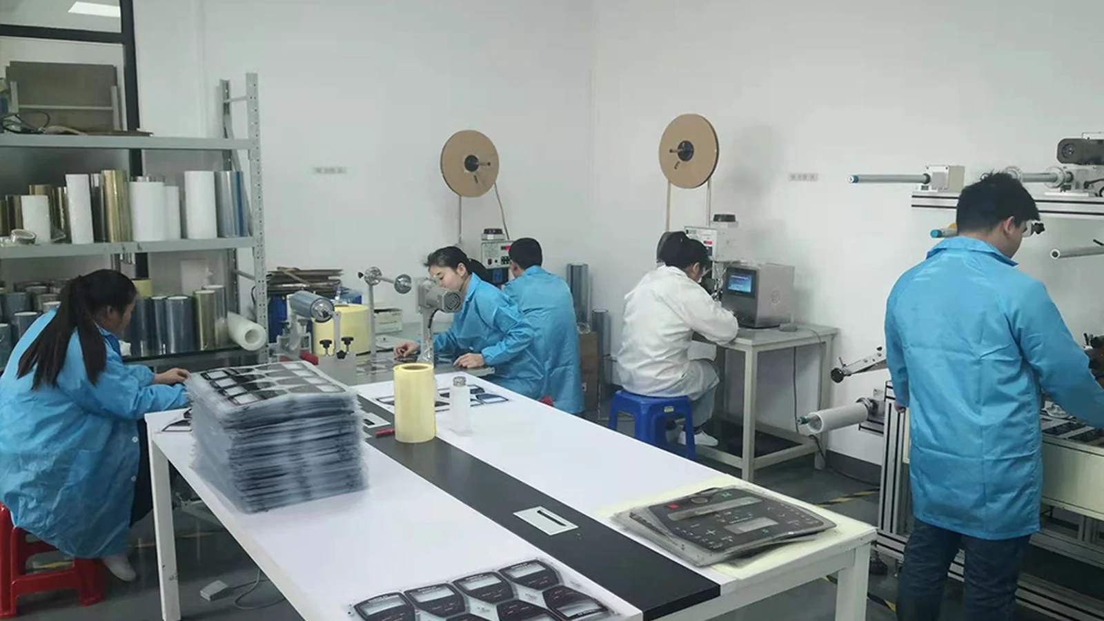
A polished front view is not an assembly definition. Release depends on the hidden interfaces: what locates the display, what loads the gasket, where the touch field sees ground, how the FPC reaches its connector, and which revision was actually tested. JASPER's published HMI assembly scope can include the front surface, input device, display or window, PCB or FPC, interconnect, connector, carrier, gasket, mounting features, and agreed checks. A quotation still has to name the parts and evidence included in that specific handoff.
What This Checklist Controls—and What It Does Not
This checklist controls the physical interfaces that turn acceptable components into one buildable operator panel. For the basic component boundary, see what an HMI panel is. The checklist starts with the operator task, follows loads and signals through the assembly, and ends with evidence tied to a released revision. ISO 9241-210:2019 supplies the broader human-centred lifecycle context. ISA-101 covers process-automation HMI behavior and management. Neither document supplies the mechanical stack, connector route, gasket joint, or drawing tolerance for a particular front panel.
The first architecture decision is the purchased boundary. Integration can remove receiving and assembly steps, but it can also make repair, alternate sourcing, and qualification changes more expensive.
| Purchased construction | Use it when | It is not the best choice when | Evidence needed before release |
|---|---|---|---|
| Bonded overlay or keypad module | The OEM owns the display, PCB, enclosure, and final seal | The front surface must be replaced without disturbing adhesive or graphics | Mating-surface drawing, placement datum, bond process, cosmetic and circuit acceptance |
| Touch-display module | Cover, sensor, display, controller, and tuning must be controlled together | The display is a field-replaceable unit or must have an independent second source | Powered optical states, touch test states, ground/EMC configuration, repair decision |
| Enclosure-mounted HMI front | One supplier should deliver a fitted operator-facing module | The equipment enclosure owns a regulated seal or structural qualification that cannot be delegated | Closure/load path, gasket joint, mounting state, connector access, installed verification |
| Separate service modules | Displays, controls, or electronics need independent replacement and revision control | Assembly labor, alignment variation, and multi-supplier interfaces create greater lifecycle risk | Interface-control drawings, separate acceptance records, final integration test |
Front layer, seal, display, input, housing fixation, cable, and PCB connection affect one another. An air-gap touch/display construction can preserve disassembly, while optical bonding removes the internal air gap and makes separation harder. This is a service decision, not a universal winner.
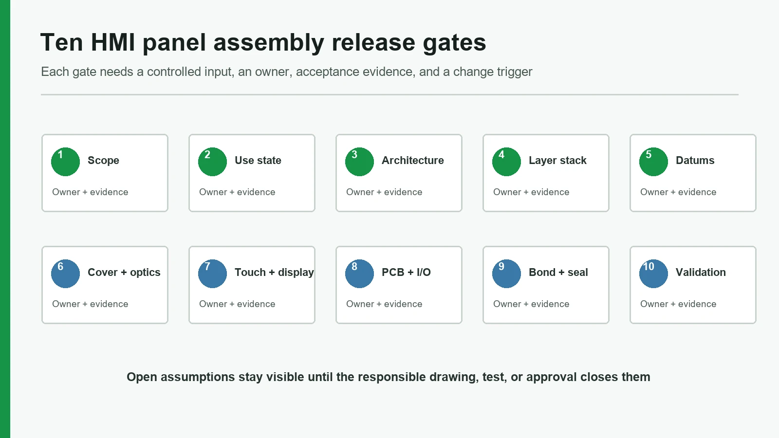
HMI Panel Assembly Design Checklist: The 10 Release Gates
A gate closes only when the drawing package contains a controlled input, a named owner, and reviewable evidence. “Supplier to confirm” is an open question, not an owner. The summary table can serve as the front page of a design-review record.
| Gate | Decision to close | Minimum release evidence |
|---|---|---|
| 1 | Operator tasks, exposure, and responsibility | Use-state matrix and responsibility boundary |
| 2 | Integrated versus serviceable architecture | Purchased-boundary decision and replacement plan |
| 3 | Layer order in every functional zone | Zone-specific stack sections with controlled materials/revisions |
| 4 | Datums, critical dimensions, tolerance, and load path | Datum scheme, critical-characteristic list, worst-case stack review |
| 5 | Cover/overlay, artwork, and optical state | Released artwork, surface spec, window geometry, visual acceptance states |
| 6 | Touch sensor, display, controller, and grounding | Production-intent powered stack and tuning/test record |
| 7 | PCB/FPC mounting, ground, heat, and test access | Board revision, keep-outs, support scheme, channel map, test boundary |
| 8 | Connector, tail, cable, and service route | Exact mating pair, orientation, routing, strain relief, access check |
| 9 | Adhesive, gasket, enclosure joint, and ingress boundary | Named materials, surface/process spec, gap/compression review, enclosure test plan |
| 10 | Validation levels, approval, and change control | Test matrix, approved sample, deviation log, trigger-to-retest matrix |
Gate 1 — Freeze Operator Tasks, Exposure, and Ownership
For industrial control applications, HMI panel design begins with the states the hardware must support. Record what the operator sees when power is off and on, what must be touched or pressed, the viewing distance and ambient light, glove or wet-hand conditions, cleaning chemistry, contamination, expected service access, and any action with a safety consequence. The hardware team does not need to write the PLC program, but it must know which icon, key, indicator, and display state the program will drive.
Turn those inputs into a responsibility matrix. Name who releases the enclosure, artwork, display model, sensor, controller, firmware, PCB, connector, harness, gasket, test fixture, and finished-equipment requirement. ISO 9241-210 supports lifecycle treatment of human-system interaction; it does not transfer final machine responsibility to the panel assembler.
Each supplied and mating item has a part/revision owner, an approval owner, and a stated handoff condition.
The RFQ says “complete HMI” while display supply, firmware, enclosure, sealing, and system validation remain undefined.
Gate 2 — Choose the Assembly Boundary and Service Strategy
Decide what arrives as one part number and what remains separately replaceable. The choice affects fixtures, incoming inspection, repair, spare-parts policy, alternate sourcing, packaging, and retest scope. A touch-display module may reduce alignment work at the OEM, but a display failure can then require replacement of a larger bonded unit. A separate display preserves service access but moves alignment, cleanliness, cable routing, and final test into the OEM's process.
Record the answer before adhesive land, bezel depth, fastener access, or cable length becomes fixed. If optical bonding, perimeter bonding, or a captured gasket makes disassembly destructive, the service drawing and spare strategy must say so. A fully integrated HMI assembly is not automatically the better construction. If the architecture choice is still open, compare an HMI panel with a membrane switch panel before fixing the purchased boundary.
The architecture record names the purchased boundary, replacement unit, destructive joints, expected service action, and evidence repeated after repair.
Integration is selected only because the assembly looks thinner or “more finished,” with no repair or qualification analysis.
Gate 3 — Draw One Controlled Stack for Every Functional Zone
An industrial HMI stack up is not one generic cross-section. The display window, touch-only area, tactile-key area, indicator window, perimeter seal, fastener, and cable exit can have different layers and load paths. Draw a section through each critical zone. Name the visible surface, print side, cover or overlay, sensor or switch, spacer, adhesive, display, PCB, support, gasket, enclosure, and protective liner.
Assign a material or part number and revision wherever a substitution can change fit, optics, touch response, force, sealing, or assembly sequence. Show intentional air gaps and their purpose. JASPER's lamination and assembly guidance treats layer order, orientation, datums, pressure, surface condition, routing, hidden-feature checks, and protection as controlled assembly inputs.
Each critical zone has a section view tied to the BOM, artwork, mating enclosure, and assembly sequence.
The drawing contains an exploded marketing render but no controlled Z-direction dimensions, gaps, liners, or process state.
Gate 4 — Establish Datums, Critical Dimensions, and Load Paths
The HMI assembly drawing needs one coordinate relationship among the enclosure opening, cover outline, printed graphics, touch electrodes, display active area, PCB holes, connector, gasket, and inspection fixture. ASME Y14.5-2018 (R2024) provides the language for geometric dimensioning, tolerancing, and datum references. It does not choose suitable numeric tolerances for the design.
Identify which features are functionally critical, then calculate the worst-case path. “Center display in window” is ambiguous unless the drawing says whether the reference is the display outline, active pixels, recommended viewing area, mask opening, or lit image. Treat gasket closure as a force stack as well as a dimension stack: fastener spacing, enclosure stiffness, cover support, gasket force, and display clearance interact.
Critical features reference a declared datum system, have measurable acceptance, and identify the clamped or free state used for inspection.
Every supplier centers its part to a different nominal outline, while the final drawing relies on unspecified general tolerances.
Gate 5 — Release the Cover, Overlay, Artwork, and Optical States
Specify the front surface by material grade, thickness, coating, texture, print system, print side, color reference, edge condition, and exposure—not simply “polyester,” “polycarbonate,” or “glass.” PET and polycarbonate selection is a tradeoff among flexing, abrasion, chemicals, printing, embossing, texture, and appearance. No polymer wins every condition.
Tie icons, key legends, indicator windows, and display masks to product datums. Define cosmetic zones and viewing conditions. For a dead-front effect, approve both powered and unpowered states. When chemistry or optics matter, name the exposure and measurement method: ASTM D543-21 addresses application-specific chemical exposure of plastics, while ASTM D1003-21 measures haze and luminous transmittance of planar transparent plastics. Neither method alone proves complete HMI cleanability or readability.
Released artwork and mechanical files share coordinates, and visual acceptance states name lighting, power, background, distance, and specimen revision.
Artwork is approved as a floating PDF while window registration, print orientation, cleaner exposure, and powered appearance remain unspecified.
Gate 6 — Validate Touch, Display, Controller, and Ground as One State
The touch sensor cannot be approved independently of its cover and electrical surroundings. For capacitive implementations, use the capacitive touch switch design guide to define the sensor, cover, grounding, and tuning boundary. Cover thickness, sensor geometry, shielding, nearby ground, conductive coatings, adhesive, voids, tuning, and post-bond testing are touch-system variables.
Freeze the sensor and controller revisions, cover and bond stack, display model, active image area, mask, support, grounding, shielding, cable state, firmware/tuning owner, and intended wet/glove conditions. Keep pressure off display glass and polarizer unless the selected module permits it; Newhaven Display's usage guidance calls for controlled glass loading, flex routing, connector insertion, and contact cleanliness. Use the chosen display's own drawing for numeric limits.
A powered production-intent assembly passes defined optical and touch states in representative enclosure, cable, ground, and firmware conditions.
A bare sensor demo or display continuity check is treated as approval of the closed, powered HMI.
Gate 7 — Control PCB/FPC Support, Ground, Heat, and Test Access
Release the PCB or FPC part number and revision, outline, thickness, mounting holes, component-side orientation, height keep-outs, standoffs, fasteners, washers, ground contacts, connector positions, test points, and programmed state. Show how insertion force, key force, or enclosure closure reaches supports instead of bending the board or loading a display.
Separate four evidence levels: bare-board design, populated-board workmanship, HMI subassembly function, and host-system behavior. IPC's board-design standards provide generic and sectional design requirements when the contract invokes them. IPC J-STD-001J and IPC-A-610J address soldering and post-assembly acceptance; they do not define the HMI's channel map, software, thermal path, or complete-machine test.
The drawing maps every key, touch channel, LED, display connection, ground, and test point from the visible feature through the connector.
“HMI PCB” appears as a single BOM line with no support state, keep-outs, grounding, test access, firmware owner, or host boundary.
Gate 8 — Freeze the Connector, Tail, Cable Route, and Service Access
Specify the exact connector and mating connector, manufacturer part numbers, contact count, pitch, keying, latch, contact side, insertion direction, cable or FPC thickness, tail datum, exposed-contact orientation, and approved alternate policy. Then draw the installed route: free length, bend and no-bend zones, transition support, clamp, strain relief, sharp-edge clearance, fastener clearance, gasket crossing, and service loop.
Flexibility does not remove geometry. A short tail can pull a sensor away from its datum; excess cable can foul the seal or block a fastener. The Hirose FH50 catalog is one part-specific example that controls FPC geometry, insertion, actuator space, and bending near the connector. Its dimensions apply to FH50, not to every connector.
A service trial proves that the mating pair can be inserted, latched, inspected, and removed in the installed state without loading adjacent parts.
The assembly drawing shows a connector symbol but omits contact side, mating part, cable state, access envelope, and strain relief.
Gate 9 — Separate Bonding, Gasketing, and Enclosure Sealing
Adhesive may locate a part, carry structural load, join an optical stack, hold a gasket before closure, or help form an environmental barrier. Those functions need separate acceptance. Adhesive selection must evaluate substrate, thickness, flatness, differential movement, temperature, surface preparation, and pressure. ASTM D3330/D3330M-04(2025) supports controlled peel testing but cautions that peel results may not provide functional design information.
For the gasket, define the complete sealing path, joint, gap range, material and grade, thickness, width, locating feature, closure method, access cycles, and compression-force effect on the cover, display, PCB, and enclosure. Gap, width, surface, secondary layers, and closure stiffness control the installed sealing state. Do not copy one generic compression percentage.
IEC 60529 classifies protection provided by an enclosure. An overlay, adhesive, or gasket does not make the installed HMI IP-rated by itself.
The drawing and process identify the joint, actual substrates, preparation, gap extremes, closure force path, specimen, and enclosure-level acceptance.
A material datasheet or loose-gasket claim is presented as proof of the finished enclosure rating.
Gate 10 — Link Validation, Approval, and Change Triggers
Build the test matrix from failure modes, not from a borrowed list of equipment. Each row needs the requirement, specimen level, revision, mounting and powered state, exposure or stimulus, method, acceptance, data record, owner, and retest trigger. JASPER's testing and validation planning separates routine production checks from design validation and asks projects to name characteristic, condition, method, stage, and acceptance owner.
Measurement equipment is only part of the evidence. Measurement-process evidence covers repeatability, reproducibility, stability, calibration, and uncertainty. Record the fixture, datum simulation, operator method, resolution, and clamped state used for a critical HMI dimension.
Close the gate with an approved production-intent sample, open-item register, deviation history, and trigger-to-retest matrix. JASPER's engineering change-control page is one internal reference for connecting active files, approved samples, deviations, and authorized changes.
Every result identifies the tested revision and state, while every material, component, tooling, firmware, supplier, or enclosure change points to a defined review.
“Passed validation” appears without a specimen revision, condition, acceptance criterion, owner, or change rule.
Industrial HMI Stack Up: What the HMI Assembly Drawing Must Show
The drawing package should let a reviewer follow every visual, mechanical, electrical, and sealing interface without guessing. The order below is illustrative; key, display, and perimeter zones often branch into different sections.
Operator / cleaner / ambient environment
Cover lens, graphic overlay, or bezel
Print, mask, adhesive, optical bond, or intentional air gap
Touch sensor, membrane switch, silicone keypad, or discrete control
Display, indicator, light guide, PCB/FPC, and ground reference
Connector, cable, clamp, strain relief, and service loop
Carrier, gasket, fasteners, enclosure joint, and machine handoff
Six Steps from Design Inputs to Production Release
Step 1 — Freeze the Use and Ownership Matrix
Collect operator states, environment, cleaning, mating enclosure, regulatory context, service plan, annual demand assumptions, and named owners. Mark unknowns; do not hide them inside supplier notes.
Step 2 — Select the Purchased Boundary
Compare separate, bonded, display-integrated, and enclosure-mounted routes. Choose the smallest boundary that closes the critical interfaces without sacrificing required replacement, sourcing, or qualification control.
Step 3 — Release the Review Package
Issue indexed drawings, models, artwork, BOM, component data, pin map, stack sections, responsibility matrix, and open-item register under one revision hierarchy.
Step 4 — Prototype by Interface Risk
Use JASPER's prototyping framework or an equivalent supplier process to build the smallest sample that answers the next irreversible question. Label every deviation from production intent.
Step 5 — Approve the Production-Intent Assembly
Review appearance, fit, touch/key input, display, connector, routing, closure, sealing path, service access, inspection method, and host correlation in the intended state. An approved photo alone is insufficient.
Step 6 — Lock Evidence and Change Triggers
Connect the approved sample, active files, BOM, alternates, work instructions, fixtures, test limits, packaging, deviations, and retest rules to the released part number.
Validation Matrix: Test the Failure at the Right Level
Environmental standards define methods; the project defines applicability, specimen, severity, operating state, and acceptance. For example, IEC 60068-2-6:2007 addresses sinusoidal vibration, IEC 60068-2-27:2008 addresses shock, IEC 60068-2-14:2023 addresses temperature change, and IEC 60068-2-78:2025 addresses steady-state damp heat without condensation. IEC 61000-4-2:2025 supplies a reproducible ESD-immunity method but does not choose a product's test level or performance criterion.
| Failure to prevent | Representative specimen/state | Evidence and acceptance boundary |
|---|---|---|
| Graphic, touch, or display misregistration | Clamped production-intent assembly | Datum-based dimensional/visual report; drawing owner accepts |
| Missed or false touch | Powered final stack in representative enclosure | Defined finger/glove/moisture states and recovery; controller/system owner accepts |
| Bond lift or window shift | Actual substrates, preparation, load, and exposure | Bond/process evidence plus assembly inspection; peel data alone is not design proof |
| Water or dust ingress | Complete enclosure revision with all penetrations | Project-defined IEC 60529 test where required; equipment owner accepts |
| Shock, vibration, or climatic damage | Installed revision with production supports and cables | Applicable method, severity, operating state, post-test function, and owner defined |
| ESD upset or damage | Accessible finished assembly in named modes | IEC 61000-4-2 method where applicable; product performance criterion defined |
| Wrong channel or intermittent connection | Closed assembly and intended mating harness | Pin-map, continuity, actuation, strain, and host-correlation evidence |
The typical failure chain is short: missing use condition → assumed interface → unrepresentative sample → hidden assembly change → system-level failure. Read every symptom back through that chain before replacing a component.
Eight Release Blockers That Stop Release
- No responsibility matrix — “complete” still has several meanings.
- No common datum scheme — graphics, sensor, display, and enclosure can each be correct but misaligned.
- Only one attractive cross-section — functional zones and force paths remain hidden.
- Uncontrolled alternates — matching descriptions do not prove matching geometry or behavior.
- A datasheet is treated as assembly evidence — substrates, process, enclosure, and loads differ.
- The prototype is not production-intent — its approval cannot close changed materials or processes.
- Tests lack specimen state and acceptance — a method name alone cannot produce a decision.
- Changes have no retest triggers — old evidence silently follows a new stack.
Frequently Asked Questions
What should an HMI panel assembly design checklist include?
An HMI panel assembly design checklist should include scope, use conditions, architecture, layer stack, datums, tolerances, cover/optics, touch/display, PCB/FPC, connector routing, adhesive, gasket, enclosure, validation, approval evidence, and change triggers. Each item needs an owner and acceptance record.
What belongs in an HMI assembly drawing?
An HMI assembly drawing should show zone-specific sections, datums, critical dimensions, free and clamped states, materials and revisions, display/touch coordinates, PCB supports, connector orientation, cable route, bond land, gasket path, fasteners, mating enclosure, and referenced inspection criteria.
How should an industrial HMI stack up be documented?
Document an industrial HMI stack up from the operator surface to the enclosure, with a separate section for every distinct functional zone. Name each layer, material or part revision, thickness/gap state, datum, process, load or signal path, inspection, and change trigger.
Who owns HMI panel design tolerances?
The design authority owns functional limits; suppliers contribute process capability and measurement methods. The released package should name who sets each critical requirement, who manufactures it, who measures it, and who accepts it. A supplier should not invent a missing system tolerance.
Does an IP-rated gasket make the HMI panel IP-rated?
No. IEC 60529 applies an IP classification to the tested enclosure configuration. Gasket material, joint geometry, gap, compression, fasteners, penetrations, assembly process, and specimen condition all affect the enclosure result; a gasket datasheet cannot transfer the rating.
Should the touch panel be tested before or after enclosure assembly?
Both tests can be useful, but final approval should occur after assembly in the representative powered enclosure. The cover, adhesive, display, nearby ground, cable, controller, firmware, moisture state, and closure can change touch behavior that a loose-sensor test cannot reveal.
When is a fully integrated HMI assembly not the best choice?
Separate modules can be better when the display needs field replacement, the OEM requires independent second sourcing, heat or structural loads need isolation, the enclosure owner must control the tested seal, or finished-equipment qualification requires final integration under the OEM's authority.
What should be submitted for an HMI stack-up review?
Submit the enclosure model, zone sections, cover/overlay drawing, artwork, touch and display data, PCB/FPC files, connector and harness details, gasket path, use conditions, responsibility matrix, test requirements, service plan, expected quantity range, and an open-item register.
Submit the HMI Stack-Up for Review
Package the latest files under one revision and state which gate each open question affects. JASPER can review a proposed physical assembly through its HMI stack-up submission route. The useful output is a written scope: supplied parts, customer parts, assembly state, inspection, prototype evidence, validation boundary, unresolved assumptions, and change path.
A related the intended evidence boundary without naming a customer, machine, quantity, field result, or certification.
Technical References
- Source: ASME Y14.5-2018 reaffirmed 2024 dimensioning and tolerancing. Accessed 2026.
- Source: ISO 9241-210:2019 confirmed in 2025. Accessed 2026.
- Source: IEC 60529 enclosure protection classification. Accessed 2026.
- Source: IEC 60068-2-6:2007 sinusoidal vibration. Accessed 2026.
- Source: IEC 60068-2-27:2008 shock testing. Accessed 2026.
- Source: NIST SEMATECH measurement process characterization. Accessed 2026.
- Source: ISO 9241-210:2019. Accessed 2026.
- Source: ISA-101. Accessed 2026.
- Source: Mekoprint's display-integration guide. Accessed 2026.
- Source: New Vision Display. Accessed 2026.
- Source: ASME Y14.5-2018 (R2024). Accessed 2026.
- Source: Tekra's PET and polycarbonate comparison. Accessed 2026.
- Source: ASTM D543-21. Accessed 2026.
- Source: ASTM D1003-21. Accessed 2026.
- Source: Microchip AN2934. Accessed 2026.
- Source: Infineon's 2026 CAPSENSE Design Guide. Accessed 2026.
- Source: Newhaven Display's usage guidance. Accessed 2026.
- Source: IPC's board-design standards. Accessed 2026.
- Source: IPC J-STD-001J and IPC-A-610J. Accessed 2026.
- Source: Hirose FH50 catalog. Accessed 2026.
- Source: 3M VHB Design Guide. Accessed 2026.
- Source: ASTM D3330/D3330M-04(2025). Accessed 2026.
- Source: Rogers' sealing guidance. Accessed 2026.
- Source: IEC 60529. Accessed 2026.
- Source: NIST/SEMATECH Measurement Process Characterization. Accessed 2026.
- Source: IEC 60068-2-6:2007. Accessed 2026.
- Source: IEC 60068-2-27:2008. Accessed 2026.
- Source: IEC 60068-2-14:2023. Accessed 2026.
Close every HMI assembly release gate
Send the controlled stack, artwork, display, circuit, connector, gasket, enclosure, validation plan, and change triggers.