
An HMI panel vs membrane switch panel decision turns on the information and operating task, not on whether a product should look “modern.” Use a display-based HMI when operators need changing values, menus, recipes, diagnostics, languages, or state-dependent controls. Use a membrane switch panel when commands and legends stay fixed, physical key location or tactile response matters, and the host electronics can read discrete or matrix inputs. Choose a hybrid when dynamic information belongs on a display but repeated actions still benefit from physical keys. This comparison is for OEM teams defining the complete interface, enclosure, software, service, and validation boundary.
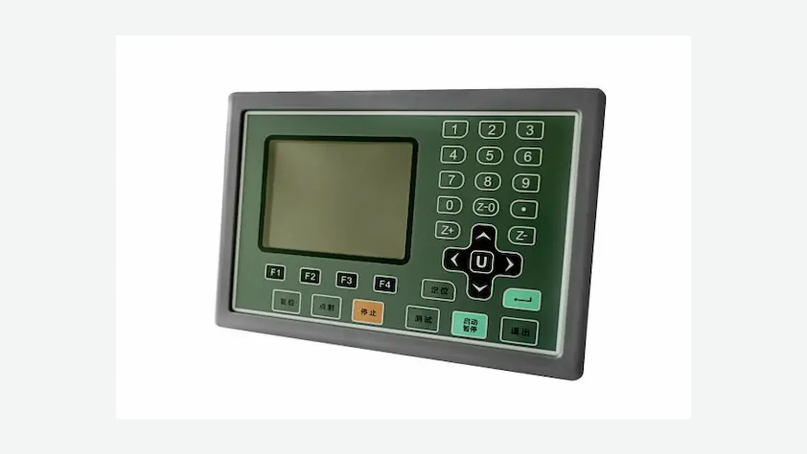
HMI Panel vs Membrane Switch Panel at a Glance
An HMI panel and a membrane switch panel are not strict opposites. A membrane switch is itself a human-machine interface when it carries commands or status. In this article, display-based HMI panel means an architecture with dynamic screen content; membrane switch panel means a fixed-graphics input and indication assembly. Industrial HMIs may use touch, a keypad, or combined inputs. “HMI” therefore does not mean “touch-only.”
| Product requirement | Display-based HMI panel | Membrane switch panel | Hybrid display + membrane keys |
|---|---|---|---|
| Changing values, menus, recipes, or diagnostics | Best fit | Needs a separate display and host logic | Best fit when stable keys remain useful |
| Few stable commands with fixed legends | Works, but may add unnecessary layers | Best fit | Useful only if a display has another clear purpose |
| Fixed physical key position or tactile snap | Needs separate keys or another feedback method | Direct option | Direct option beside the display |
| Multiple languages or frequent label changes | Screen content can change by software | New artwork or another label strategy is normally required | Fixed critical labels plus translated screen content |
| Dense alarms, records, trends, or diagrams | Best fit | Poor stand-alone fit | Best fit |
| Passive discrete or matrix host input | Requires added interface electronics | Direct fit when the circuit matches the host | Physical keys can remain on a simple input path |
| Tight rear-depth allowance | Display, board, cable, and mounting depth must be budgeted | Often favorable, but the complete stack still matters | Usually deeper than a stand-alone membrane panel |
| Field-replaceable powered module | Standard terminal can be a strong fit | Depends on adhesive, bezel, tail, and access | Depends on how the display and front assembly are separated |
| No software or runtime owner | Stop condition | Can fit if host input behavior is defined | Display portion still needs an owner |
No row acts alone. Mark each requirement as a gate, weighted criterion, or preference. Resolve gates first; a weighted score cannot compensate for a missing software owner, an impossible rear envelope, or an undefined safety function.
Compare Complete Interface Architectures, Not Isolated Parts
A fair display panel vs switch panel comparison uses the same system boundary. Comparing a powered HMI terminal with only the graphic film of a membrane switch makes the screen route look expensive and the switch route look incomplete. The correct boundary runs from what the operator sees and touches to the host response.
Membrane switch panel route
fixed graphic overlay
key geometry / tactile dome or non-tactile spacer
printed circuit and contact
tail + connector
host input scan / logic
indicator, display, or machine response
Display-based HMI route
cover / bezel + display
touch sensor or physical input
touch controller / interface electronics
HMI runtime and screen project
communication + host logic
screen, alarm, record, or machine response
A custom HMI panel hardware guide can help allocate the front surface, display, input, circuit, connector, enclosure, runtime, PLC, and machine responsibilities. The comparison in this article starts after those terms are separated.
Start With Fixed Versus Dynamic Information
The strongest early test is simple: does the command-and-information model stay fixed? Button count comes later.
A membrane switch panel fits a fixed model when each key keeps the same meaning, the legend remains stable, and status can be conveyed by fixed indicators, a small display window, or the machine itself. Start, stop, mode, reset, speed, navigation, and set-point keys can work well in this architecture when their meanings do not change by screen state. The why key geometry, legends, tail routing, connector matching, and enclosure fit must be reviewed together. It keeps key geometry, legends, tail routing, connector matching, and enclosure fit in one review.
A display-based HMI earns its extra layers when controls change by operating mode, operators browse records, the product presents trends or alarms, values require direct entry, user roles expose different functions, or languages must change without replacing artwork. Complete HMI architecture includes menu hierarchies, screen navigation, dynamic elements, alarms, security, programs, databases, servers, and networks. Those functions require data, software, communication, and validation; a display or cover lens does not create them by itself.
Touch HMI vs membrane keypad: decide the feedback channel
The touch HMI vs membrane keypad question is often really a feedback and attention question. A tactile membrane key can provide dome snap, embossed location, fixed spacing, printed legends, and local LED feedback. That may help an operator find a repeated control by position or feel. The result still depends on key size, spacing, support, glove type, posture, actuation profile, and the surrounding enclosure.
A flat touchscreen has no mechanical key travel by itself. It can return visual, audible, or haptic feedback, and the machine response may provide confirmation. Yet a color change on screen is not always proof that the controller accepted or executed a command. The same caveat applies to dome snap: it confirms a physical key event, not successful machine action.
For gloves, water, oil, or cleaning residue, avoid a category-level verdict. Record the glove material and thickness, wet and dry states, contaminants, operator posture, target size, cover stack, controller, grounding, and acceptance criteria. Sensor construction, the touch cover, and shielding are coupled capacitive-touch design inputs. Test the real installed stack rather than promising “glove operation” from a controller datasheet.
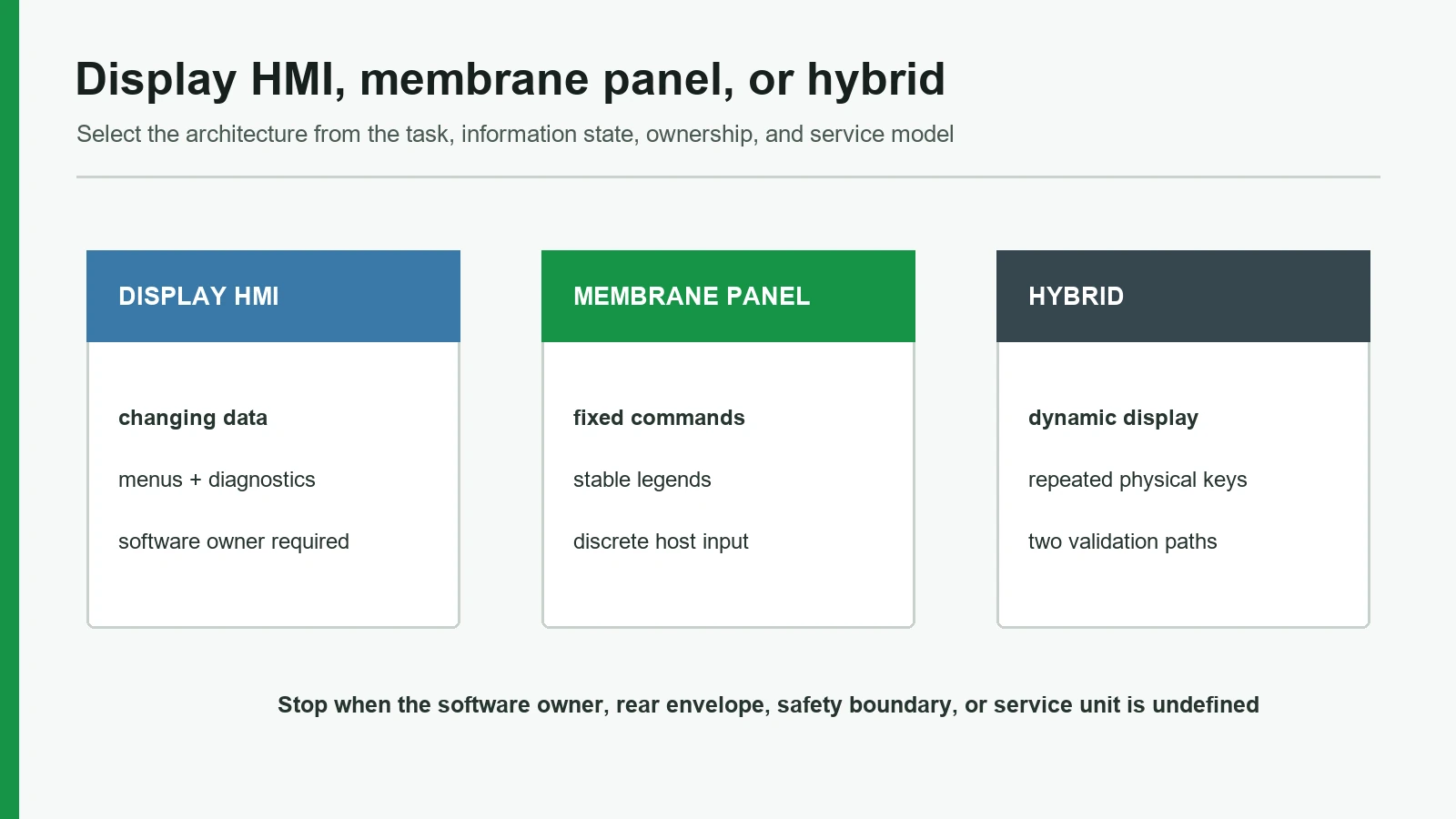
Industrial Interface Comparison Across Nine Dimensions
This industrial interface comparison treats each architecture symmetrically. “Typical direction” is not a guaranteed product specification.
| Dimension | Display-based HMI panel | Membrane switch panel | Decision boundary |
|---|---|---|---|
| Information density | Supports changing text, graphics, trends, records, and conditional controls | Supports fixed legends, indicators, windows, and discrete controls | Use a display when information must redraw or reorganize |
| Physical feedback | Touch needs visual, audible, haptic, or separate-key feedback | Domes, embossing, and fixed geometry can provide physical cues | Observe the actual task; do not infer acceptance from feel alone |
| Software dependency | Screen project, runtime, data mapping, communication, updates, and recovery may be required | Passive panel normally relies on host firmware for scanning and response | Name the owner of every executable layer |
| Installation envelope | Allow for display, board, cable bend, mounting, thermal path, and service access | Often a shallow bonded front, but domes, light guides, PCB support, connectors, and windows add depth | Compare the installed section, not face thickness |
| Sealing | Cover, bezel, gasket, housing, connector, and service joints form the boundary | Surface, perimeter adhesive/gasket, windows, tail exit, connector, and enclosure form the boundary | Verify the final enclosure configuration under IEC 60529 or the applicable product method |
| Cost structure | Display, electronics, software, configuration, enclosure, testing, and support | Artwork, printing, circuit, domes, adhesive, tooling, host inputs, and testing | Compare total integration and ownership, not one component quote |
| Service | Can be a removable terminal or a bonded custom assembly | Can be a bonded panel, bezel module, or front assembly | Define the field-replaceable unit before mounting is frozen |
| Product life | Display, controller, runtime, OS, communication, and software versions can change | Artwork, film, ink, dome, adhesive, circuit, tail, and connector can change | Assign end-of-life and substitution ownership for both |
| Validation | Physical tests plus display, touch, software, communication, state, and update tests | Visual, dimensional, circuit, actuation, bond, connector, and installed-enclosure tests | The test matrix must follow the actual architecture and use profile |
A screen is not automatically an upgrade. Fixed graphics are not automatically obsolete. Each route is efficient when its stable and variable elements match the product.
Software and Signal Ownership Often Decide the HMI Route
A display-based HMI can move labels and workflows into software, but that flexibility has owners. The project must identify who controls the screen hierarchy, data tags, units, permissions, alarm presentation, stale-data behavior, boot state, communication loss, localization, firmware, release approval, update delivery, rollback, and field support.
A passive membrane panel has fewer executable layers, yet it is not independent of software. Host firmware must scan the contacts, debounce the input, interpret a matrix, drive indicators, reject invalid combinations, and produce the machine response. Changing a printed RESET legend may also require logic, documentation, and validation changes.
| Ownership item | Display-based HMI | Membrane switch panel |
|---|---|---|
| Visible labels and controls | Screen project plus any fixed bezel artwork | Printed overlay artwork |
| Input interpretation | Touch controller, HMI runtime, protocol, and host logic | Host input scan, matrix logic, and debouncing |
| State feedback | Screen objects, alarms, indicators, and machine state | LEDs, separate display, machine response, and host state |
| Version control | Hardware, firmware, runtime, screen project, configuration, and protocol | Artwork, circuit, pinout, BOM, host firmware, and connector |
| Fault isolation | Power, display, touch, controller, runtime, communication, host data | Contact, circuit, tail, connector, indicator, host input |
If the project wants a supported runtime, standard communication drivers, and modular field replacement, an established powered terminal may be preferable to a fully custom HMI assembly. A standard terminal can be a better choice than a custom assembly when its software environment and service model fit the machine. JASPER is relevant when the OEM needs a custom physical front-panel or hybrid assembly and retains ownership of the wider control system.
Thickness, Sealing, Cleaning, and Service Share One Boundary
A membrane panel often starts with a shallow front stack, but “thin” is not an installation specification. Draw the front projection, enclosure cutout, rear depth, connector and tail path, cable bend, PCB/display support, adhesive or fastener area, assembly sequence, and removal route. A light guide, display window, rigid backing, connector, or support plate can control the envelope even when the overlay itself is thin.
A display HMI normally needs space for the display module, controller or interface PCB, cables, mounting features, thermal path, and service access. A compact front view can hide a rear collision with a bracket, harness, battery, duct, or service tool.
Ingress protection is also an installed-system property. IEC 60529 classifies degrees of protection provided by enclosures. For a membrane panel, inspect the perimeter, window, indicator opening, tail exit, connector, enclosure seam, fastener, and bond surface. For a display HMI, inspect the cover, optical stack, bezel, gasket, housing, connector, rear enclosure, and any removable joint. A loose overlay, cover lens, adhesive, or gasket does not transfer an IP rating to the machine.
Cleaning requirements need equal precision. Name the agent, concentration or application method where known, contact time, frequency, temperature, abrasion, and whether the surface is wiped, sprayed, rinsed, or exposed during operation. “Easy to clean” is not an acceptance criterion.
Define the replaceable unit before selecting permanent adhesive or buried connectors. A bonded membrane panel can provide a continuous surface but may be damaged during removal. A removable powered terminal can simplify swap-out but needs a controlled cutout, gasket compression, fasteners, cable access, compatible configuration, and spare-unit plan. Neither architecture wins serviceability by name.
Compare Total Integration Cost and Product-Life Risk
There is no defensible universal price crossover between an HMI panel and a membrane switch panel. Dimensions, display technology, electronics, tooling, volume, software, enclosure design, validation, component availability, and field support change the answer. A sourcing table that compares only two unit prices compares unequal systems.
| Cost / lifecycle element | Display-based HMI panel | Membrane switch panel |
|---|---|---|
| Front hardware | Cover or overlay, printing, touch, display, bezel/gasket, mounting | Graphic overlay, circuit, spacer, domes, windows, LEDs, adhesive/gasket, tail |
| Electronics | Display interface, touch controller, processor/interface board, power, communication | Host scan inputs, optional PCB, indicators, backlight, connector |
| Software | Screen project, runtime, data map, localization, updates, regression | Host input logic, indicator logic, and any separate display software |
| Initial integration | Mechanical stack, optical alignment, cables, power, protocol, software states | Key feel, circuit/pinout, support, window alignment, tail, connector, enclosure bond |
| Change path | Screen/firmware change, module substitution, protocol or hardware migration | Artwork, circuit, dome, material, adhesive, tail, connector, or tooling revision |
| Field support | Module, cable, firmware, configuration, runtime, or complete terminal | Bonded panel, front assembly, tail, connector, indicator, or host input |
| Obsolescence owner | Display, controller, processor, runtime, OS, communication components | Film, ink, adhesive, dome, printed circuit, connector, LED/backlight |
For a stable command set, display and software layers may add cost without adding information value. For a variable workflow, forcing everything into fixed keys can create crowded artwork, excess indicators, multiple language variants, or repeated hardware revisions. The lower-risk architecture is the one whose expected changes are easier for the OEM to control.
Validate the Selected Architecture Under Real Conditions
The approval plan should trace each operator action from input to machine response. An appearance mockup can answer layout questions. It cannot validate circuit behavior, touch tuning, sealing, communication, recovery, software states, or service.
| Validation area | Membrane switch panel | Display-based HMI panel | Hybrid-specific check |
|---|---|---|---|
| Visual and dimensional | Artwork, color tolerance, registration, key/window position, outline, tail | Cover/bezel, visible and active areas, display alignment, pixel/visual criteria, cutout | Screen and fixed legends agree in every state |
| Input | Actuation profile, release, contact resistance, continuity, shorts/opens, pinout | Touch mapping, edge targets, gestures if used, false/missed touches, physical keys if present | A fixed key never gains an ambiguous screen-dependent meaning |
| Environment | Installed bond/gasket, agents, temperature, humidity, vibration, contaminants | Installed cover/bezel/gasket, optical stack, moisture, gloves, grounding, shielding | Both input paths remain coherent under the same exposure |
| Electrical / communication | Matrix scan, debounce, LEDs/backlight, connector, host response | Power interruption, boot, communication loss, stale data, grounding, EMC/ESD plan | Keys, indicators, display, controller, and host recover to a known state |
| Life / wear | Define cycles, load, rate, environment, acceptance, and failure criteria | Define touch use, display/backlight duty, controls, connectors, software support, and failure criteria | Include repeated physical actions and display-state transitions |
| Software / state | Host input logic and indicator response | Navigation, permissions, alarm/state behavior, localization, update, rollback, diagnostics | Regression covers every key-to-screen mapping |
| Service | Removal, adhesive damage, tail access, replacement fit, revision identity | Removal, glass protection, fastener/gasket reuse, configuration, compatible versions | Replacing one subassembly does not break the other path |
ASTM F1578-24 provides a method for contact-closure cycling of a membrane switch. It requires a defined setup and predetermined cycle count; voltage and current may also be specified. The method is a useful planning reference, but it does not justify a universal cycle-life claim. Record construction, actuator, force or displacement method, rate, electrical load, environment, sample size, acceptance criteria, and post-test inspection.
For capacitive input, sensor, cover, and shielding choices interact. Validate the production-intent cover thickness and material, print or adhesive stack, controller, grounding, enclosure, moisture, gloves, cables, nearby conductors, and firmware settings together.
Human interaction also needs lifecycle validation. ISO 9241-210:2019 frames human-centred design as work across the lifecycle of an interactive system. For this decision, that means observing real tasks, testing error and recovery paths, and re-checking the interaction after hardware or software changes. Citation of the standard does not claim that JASPER or the finished product conforms to it.
HMI Panel vs Membrane Switch Panel Decision Matrix
Use the first column as a gate list, not a tally sheet.
| If the product condition is… | Select first | Why |
|---|---|---|
| Stable commands, fixed labels, simple host inputs, no need for rich data | Membrane switch panel | Fewer display/runtime layers; fixed physical map matches the task |
| Menus, recipes, trends, detailed alarms, records, roles, or changing controls | Display-based HMI | Dynamic information and state-dependent interaction justify the screen/software stack |
| Dynamic information plus repeated or physically located actions | Hybrid HMI | Screen carries context; membrane keys keep stable actions fixed |
| Standard runtime, communication drivers, modular replacement, and known cutout are priorities | Standard powered HMI terminal | Established terminal ecosystem may reduce custom system development |
| No software owner, but a display workflow is required | Neither yet | Assign runtime, data, release, update, and support ownership before selection |
| IP or cleaning target exists but the enclosure and interfaces are undefined | Neither yet | Complete the installed boundary and test plan first |
| Safety-related action is being moved to a general touch screen | Separate safety analysis required | This article does not establish a safety architecture or regulatory control strategy |
| Appearance is the only reason to add a display | Re-test the information model | A screen without dynamic information may add unnecessary cost and lifecycle work |
When a membrane switch panel is not the best choice
Do not choose a stand-alone membrane panel when controls change heavily by state, operators must read dense or graphical information, language variants would multiply artwork, future functions depend on flexible workflows, or fixed labels and indicators become crowded. More printed keys do not solve an information-architecture problem.
When a display-based HMI is not the best choice
Do not choose a display-based HMI when the product has only a few stable commands, the screen adds no useful information, no team owns software and field support, rear depth or power is unresolved, or the product cannot manage display/controller obsolescence. A screen is not a default upgrade.
When hybrid is not the best choice
Do not choose hybrid merely as a compromise. It inherits the physical panel, display, electronics, software, cross-state, sealing, and service work. Hybrid is justified only when dynamic information and stable physical actions each have a documented task.
Project Input and Sample Approval Checklist
Send one controlled package before artwork and tooling are released:
- Operator and task: user roles, posture, reach, gloves, lighting, repeated actions, error consequences, and environment.
- Information inventory: commands, status, alarms, values, records, trends, languages, and which items are fixed, conditional, or dynamic.
- Architecture drawing: front outline, cutout, rear envelope, stack, support, cable path, connector access, fasteners/adhesive, and removal route.
- Electronics: display/touch drawings, active areas, PCB/FPC, pinout, power, host inputs, communication, grounding, shielding, and indicator loads.
- Software ownership: runtime, PLC/host logic, screen project, data map, permissions, localization, diagnostics, update, rollback, and cybersecurity responsibilities.
- Environment: actual cleaning agents and method, moisture, contaminants, temperature, humidity, vibration, impact, storage, and ingress target.
- Lifecycle and service: product-life target, replaceable unit, spares, revision identity, obsolescence owner, and approved-substitution process.
- Validation: prototype purpose, production-intent differences, test methods, sample size, acceptance criteria, traceability, and change-control triggers.
Use membrane switch prototyping to answer declared physical questions such as key feel, registration, window alignment, tail route, connector fit, and enclosure installation. Do not treat a physical sample as proof of HMI runtime, communication, IP, finished-device compliance, or field life.
Frequently Asked Questions
What is the main difference between an HMI panel and a membrane switch panel?
A display-based HMI panel presents dynamic information and normally adds display electronics, software/runtime, communication, and state validation. A membrane switch panel uses fixed graphics and discrete physical inputs interpreted by the host. Both are HMIs; this comparison distinguishes their complete architectures.
Is a membrane switch panel an HMI?
Yes. A membrane switch panel is a human-machine interface when an operator uses it to issue commands or read status. HMI panel is often used commercially for a display-based terminal, but the broader engineering term also includes fixed-key interfaces.
Can an HMI panel use membrane switches?
Yes. A hybrid HMI can combine a display with membrane keys, indicators, a PCB or FPC, connector, and coordinated front surface. Siemens and Rockwell Automation documentation also confirms that industrial HMI products can combine screens and physical keys, although their terminal architectures differ from a custom assembly.
Which is better for gloves: a touch HMI or membrane keypad?
Neither wins without test conditions. Define glove material and thickness, moisture, contaminants, posture, target geometry, cover stack, controller, grounding, key profile, and feedback. A tactile key may aid physical location; a touch HMI needs tuning and installed-stack validation.
Which architecture costs less?
There is no universal answer. Compare the complete front hardware, display, electronics, software, tooling, enclosure, integration, validation, changes, service, volume, and obsolescence plan. A membrane panel often carries fewer executable layers; a display may avoid repeated artwork and support dynamic workflows.
Can a membrane switch panel include a display window?
Yes. It can include clear or tinted windows, printed masks, LEDs, backlighting, and keys around a separate display. The OEM still controls the display drawing, active area, alignment, support, connector, software, and enclosure stack.
Does either architecture automatically meet an IP rating?
No. IEC 60529 applies to protection provided by enclosures. The rating depends on the tested installed configuration, including perimeter, windows or cover, gasket or adhesive, tail/cable exits, connectors, fasteners, seams, and assembly process.
Which architecture lasts longer?
No universal life number answers that question. A membrane panel has graphic, contact, dome, circuit, adhesive, connector, and enclosure failure modes. A display HMI adds display, backlight, touch, controller, software, communication, and obsolescence risks. Define use conditions, failure criteria, and test methods for the actual construction.
Select the Interface Architecture Before Freezing the Front Panel
Prepare the task list, information inventory, enclosure section, display and electronics drawings, input map, software ownership, environment, service plan, product-life target, and validation matrix. Then use the JASPER project inquiry to decide whether the physical route should be a membrane switch panel, custom display-based HMI assembly, hybrid front, or another architecture. This step should occur before detailed artwork, component commitments, and tooling release.
Technical References
- Source: NIST SP 800-82 Rev. 3 Guide to Operational Technology Security. Accessed 2026.
- Source: ISA-101.01-2015 Human Machine Interfaces for Process Automation Systems. Accessed 2026.
- Source: ISA-TR101.02-2019 HMI Usability and Performance. Accessed 2026.
- Source: IEC 63303 Human-Machine Interfaces for Process Automation Systems. Accessed 2026.
- Source: ISO 9241-210:2019 human-centred design lifecycle. Accessed 2026.
- Source: IEC 60529 enclosure protection classification. Accessed 2026.
- Source: IEC 61000-4-2:2025 electrostatic discharge immunity. Accessed 2026.
- Source: Microchip AN2934 Capacitive Touch Sensor Design Guide. Accessed 2026.
- Source: International Society of Automation, “ISA101, Human-Machine Interfaces.”. Accessed 2026.
- Source: International Electrotechnical Commission, “IEC 60529:1989+AMD1:1999+AMD2:2013 CSV — Degrees of protection provided by enclosures (IP Code).”. Accessed 2026.
- Source: ASTM International, “ASTM F1578-24 — Standard Test Method for Contact Closure Cycling of a Membrane Switch.”. Accessed 2026.
- Source: Microchip Technology, “Capacitive Touch Sensor Design Guide AN2934.”. Accessed 2026.
- Source: Siemens, “SIMATIC HMI KTP700 Basic” documentation. Accessed 2026.
- Source: Rockwell Automation, “PanelView Plus 6 Terminals User Manual.”. Accessed 2026.
- Source: International Organization for Standardization, “ISO 9241-210:2019 — Human-centred design for interactive systems.”. Accessed 2026.
Select the interface architecture before artwork
Send the information states, repeated actions, glove and cleaning needs, enclosure space, host electronics, software owner, and service plan.