
Home / Case Studies / Industrial Control Membrane Keypad
Anonymous engineering case
Industrial Control Membrane Keypad for the Operator and Enclosure
An industrial keypad may pass continuity at the bench and still be awkward on the machine. Key groups, glove clearance, housing support, tail direction, connector access and installation method decide whether the interface works in place.
This page follows those decisions from the first layout review through sample approval. It describes an anonymous project type, not a published customer result.
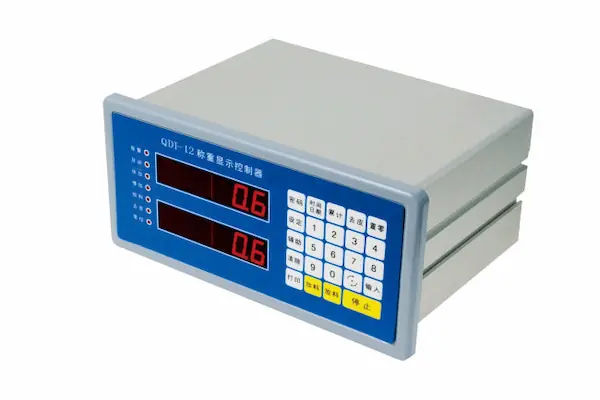
What this example does and does not claim
The project frame reflects common OEM drawing and sample reviews. It does not identify a customer or machine, and it does not claim a protection rating, chemical resistance, operating life, actuation force, order volume, delivery time or field result. Those values require an agreed construction and project-specific evidence.
Project frame
The first review starts with the machine and the operator, not with a standard keypad stack. These five points define the useful design discussion.
Electrical continuity is only one part of an industrial keypad approval
A bench tester can confirm that each key closes the intended circuit. It cannot show whether an operator can separate START from RESET while wearing gloves, whether a long legend stays readable at the normal viewing angle, or whether the connector can be reached after the panel is installed.
The housing also changes the keypad. A metal dome over a firm, even backing can feel different above a recess, rib or unsupported opening. A tail that bends neatly on a drawing may meet a bracket, sharp edge or neighboring cable inside the enclosure. Rear adhesive depends on the actual paint, texture, flatness and available bonding land.
For that reason, the sample should be reviewed as an installed machine component. The keypad layout, mechanical support, cable path and operator task belong in the same approval.
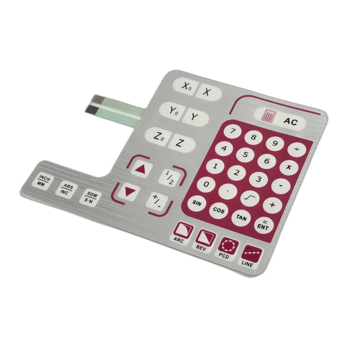
What had to be reviewed together
Each item can look reasonable on its own. Problems usually appear where operator behavior, printed graphics, mechanical support and internal wiring meet.
Task sequence and key groups
Frequently used commands, setup keys, numeric entry and emergency or reset functions need a hierarchy that reflects the actual operating sequence.
Glove clearance and key geometry
Key size, pitch, gaps, embossing and surrounding dead area influence target accuracy and accidental presses under the intended hand condition.
Tactile response and backing support
Dome, spacer, overlay and housing support work as one spring system. Final feel cannot be judged reliably from the dome specification alone.
Overlay finish and legibility
Texture, glare, color contrast, icon size, legend length and viewing angle determine whether the front panel can be read during normal operation.
Tail, connector and mounting surface
Tail exit, bend radius, stiffener, connector direction, adhesive land and housing geometry compete for space around the panel edge.
Turn the operator task into geometry before artwork is locked
The drawing should show more than key centers. It should explain which actions belong together, which ones must stay apart and how the hand approaches the panel.
Sequence
Map the commands used in one normal task
Walk through start-up, adjustment, confirmation, stop and recovery. Key grouping should follow the work, not the order in which labels were added to the artwork.
Hand condition
Review the actual glove and finger contact area
Name the glove type and size where relevant. A nominal key outline does not show the full contact patch or the space needed between adjacent embossed areas.
Critical actions
Separate commands that carry different consequences
Spacing, shape, color and position can distinguish confirmation, stop, reset and mode changes. The correct method depends on the machine and its control logic.
Visual scan
Check the panel from the normal viewing position
Long legends, low contrast and glare may look acceptable on a PDF but become slow to read once the panel is vertical, angled or below eye level.
The sample had to answer installation questions, not just drawing questions
A useful sample review puts the keypad on representative hardware and checks the details that disappear in a flat file.
Can the operator reach and distinguish the intended keys?
Run the normal task with the expected hand position and glove condition. Note mis-hits, awkward reaches, hidden legends and unclear feedback by key.
Does every key have consistent backing from the enclosure?
Check for recesses, ribs, holes, local flex and uneven adhesive support behind the active areas before tactile response is approved.
Can the tail and connector be installed without strain?
Confirm exit direction, bend path, stiffener clearance, mating access and nearby hardware on the assembled enclosure.
Does the adhesive contact the real panel surface?
Review paint or plastic type, texture, flatness, recess depth, edge clearance, cleaning before installation and the pressure used during bonding.
What the buyer should approve during sampling
The approved sample should represent how the keypad is installed and used. A loose part on a desk leaves the highest-risk conditions untested.
Install the keypad on representative enclosure hardware
Confirm outline, cutouts, support, adhesive contact, edge clearance and tail exit before key feel or appearance is signed off.
Run a normal operating sequence
Use the intended hand position and glove condition. Check key finding, spacing, feedback, legend visibility and accidental actuation.
Inspect the complete tail and connector path
Verify bend points, stiffener, connector orientation, mating access, strain at the exit and clearance from brackets or sharp edges.
Release one controlled build reference
Tie the accepted unit to the current drawing, artwork, key map, circuit, material stack, connector and written inspection notes.
Production controls that carry the approved layout into repeat builds
Once the sample is accepted, artwork, layer alignment, key mapping and connector direction have to remain linked to the same released revision.
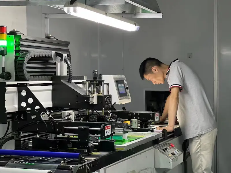
Printing and assembly
The printed overlay must stay aligned with the active key map
Legends, color blocks, windows and embossed areas are useful only when they register with the circuit and spacer below. Revision control should keep the artwork, tooling and electrical map together.
- Artwork, color reference and print revision checked before release
- Overlay, spacer, dome and circuit alignment reviewed during assembly
- Key groups, legends and visible surface inspected against the approved sample
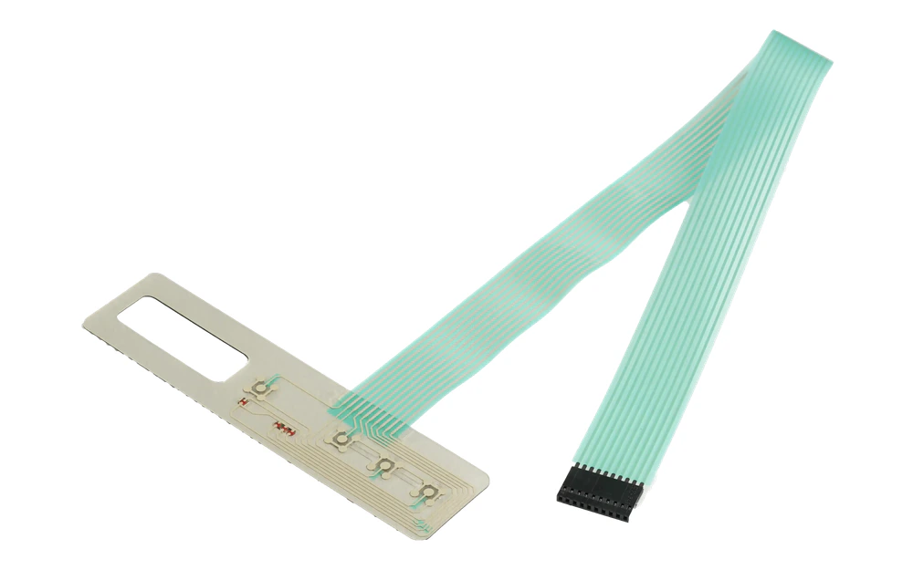
Electrical and integration check
A pass result should still identify every key and connector direction
Continuity testing confirms the circuit, but the final check should also verify key mapping, tail condition, stiffener position and connector orientation. These details determine whether the part connects correctly inside the machine.
- Continuity, open and short checks based on the released circuit
- Key-to-pin mapping and connector orientation verified
- Tail surface, bend area, dimensions and packing checked before shipment
What to send before the layout becomes expensive to change
A marked enclosure drawing and a short description of the operator task are usually more useful than a finished artwork file with no operating context.
Available area, outline, cutouts, recess depth, support surface, edge clearance and nearby hardware
Command names, grouping, critical actions, legends, icons, colors, windows and indicator positions
Normal task sequence, hand approach, glove type and size, viewing angle and any known mis-operation risk
Material, coating, texture, flatness, adhesive land, installation access and expected mounting method
Matrix or pinout, tail exit, route, bend areas, length, stiffener, connector part and mating direction
Sample context, checks by key, appearance priorities, required records and the people responsible for release
Continue the review with the underlying technical pages
This case connects operator use with the keypad construction. These pages cover the product, cable, adhesive and engineering details behind the decisions.
Questions that usually come up before a similar RFQ
Can JASPER manufacture custom membrane keypads for industrial controls?
JASPER can manufacture custom membrane keypads for industrial equipment when the layout, circuit, materials, enclosure, tail, connector, operating condition and inspection scope are defined. The final machine-level validation remains part of the buyer's project.
How should a keypad be reviewed for glove use?
Provide the glove type and size, intended hand position, critical commands and normal operating sequence. Key size, spacing, embossing and feedback should then be checked on a representative enclosure.
Can tactile force be selected from a dome data sheet alone?
A dome specification is a starting point, not the complete assembled response. Overlay, spacer, adhesive, backing support, key size and operating direction can change what the user feels.
Why does the enclosure drawing matter to the tail design?
The enclosure determines the tail exit, bend route, connector access, available strain relief and clearance from brackets, bosses, edges and other cables.
What is the minimum information needed for a first review?
Send the panel drawing or marked sketch, key map, operator and glove notes, housing surface, circuit or pinout, tail and connector requirement, and the conditions that should be approved on the sample.
Review the key map on the enclosure, not only on the artwork
Send the panel drawing, operator sequence, key map, housing surface, circuit, tail route and connector. JASPER can review the open layout and integration decisions before they become tooling or installation changes.