Dongguan, Guangdong 523927, China[email protected]+86 136 3262 5290
Home / Products / Membrane Switches / Membrane Switch Panels

Membrane Switch Panels

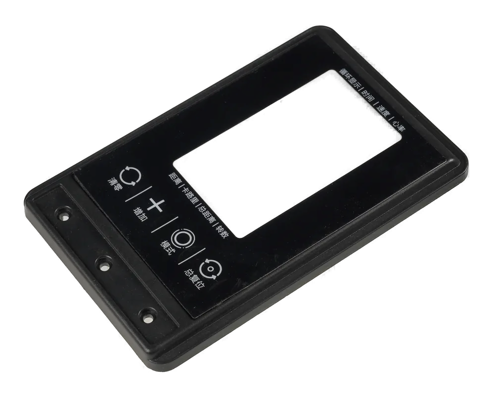
A membrane switch panel is the finished visible interface, not only the switch stack. Display windows, key zones, LEDs, graphics, perimeter adhesive, tail exit, enclosure datums, bezel clearance, and assembly sequence all compete for the same front-panel space.

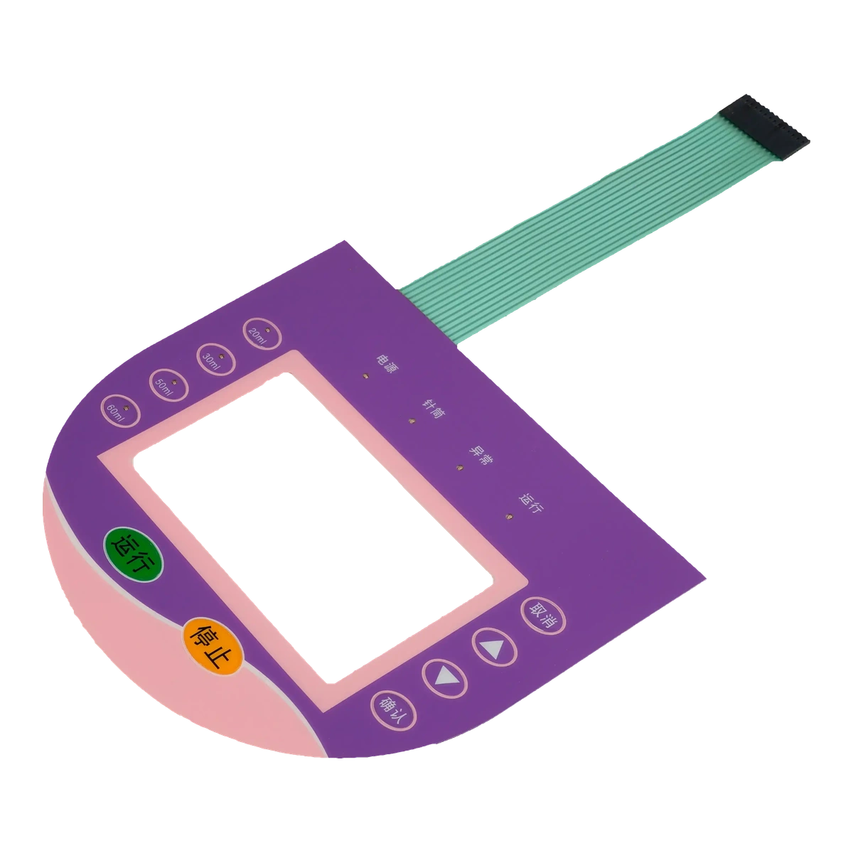
Complete membrane switch panel with display window, four control keys, status indicators, flexible tail, and connector
Front-surface zoneskeys, displays, indicators, branding, warnings, dead-front areas, and service marks
Mounting boundaryperimeter adhesive, flatness, datum, cutouts, bosses, bezel, and tail slot
Installed approvalwindow clarity, key operation, light leakage, bond, alignment, and enclosure appearance

Release the panel against the real enclosure and installed viewing condition

Panel artwork can look correct in a flat PDF and still fail when placed over a display, bezel, recessed pocket, curved housing, or uneven mounting surface. The drawing must show visible openings, hidden adhesive lands, edge clearances, and assembly datums.

Display windows need separate dimensions for the visible area, printed border, adhesive exclusion, internal display, and allowable misalignment. A window that is large enough optically may leave too little adhesive or expose enclosure hardware.

The installation process affects final quality. Tail insertion, liner removal, datum alignment, bonding pressure, cure time, surface preparation, and rework limits should be reviewed before the first production run.

Membrane Switch Panels fit when:

  • the OEM wants one ready-to-bond front interface with graphics, keys, windows, and indicators
  • the display, enclosure, adhesive land, tail route, and panel outline can be released together
  • the installed appearance and alignment can be approved on production-intent hardware
  • assembly instructions and acceptance limits can be documented for repeatable installation

Six controls connect the printed panel to the enclosure

The front artwork, hidden adhesive geometry, and mechanical housing need one coordinate system.

01

Datum and outline

Release control

Release panel origin, outline, corner radii, locating features, bezel, pocket, bosses, cutouts, and allowable edge mismatch.

If it is missing

The panel is visually shifted even though every individual dimension is in tolerance.

02

Display window stack

Release control

Define visible area, printed border, adhesive exclusion, display active area, air gap, texture, tint, and misalignment.

If it is missing

The border clips the display or adhesive enters the visible window.

03

Key and indicator zones

Release control

Align active keys, emboss, domes, LEDs, icons, dead-front areas, display, and enclosure support.

If it is missing

Keys or indicators work electrically but are visibly off-center.

04

Adhesive boundary

Release control

Control perimeter width, internal islands, surface energy, flatness, texture, contamination, gasket, and rework.

If it is missing

The panel lifts at corners, leaks, or telegraphs enclosure features.

05

Tail and assembly path

Release control

Show exit slot, bend radius, insertion direction, liner sequence, connector access, strain relief, and service path.

If it is missing

The panel bonds successfully but the tail cannot be routed or connected.

06

Installed inspection

Release control

Define alignment, bubbles, edge lift, window clarity, key feel, LED leakage, bond pressure, cure, and records.

If it is missing

A flat incoming inspection misses assembly-caused defects.

Membrane switch panel specification table

Use installed datums and acceptance conditions, not artwork dimensions alone.

DecisionOptions to reviewRelease question
Panel architectureOverlay-only, switch stack, display window, indicators, dead-front graphics, gasket, carrier, complete HMIWhat is included in the supplied front-panel assembly?
Visible geometryPanel outline, keys, legends, windows, icons, warning areas, branding, texture, colorWhich dimensions are judged by the operator and industrial designer?
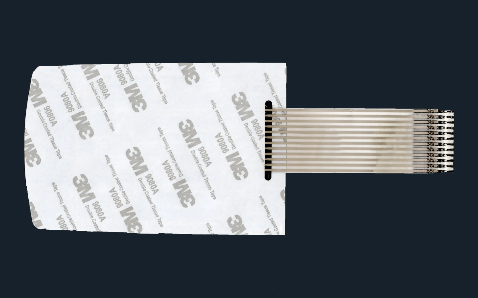
Hidden geometryAdhesive lands, venting, spacer, circuits, dome pockets, LED apertures, tail slot, keep-outsWhich hidden zones protect function, bond, and sealing?
Enclosure interfaceDatums, recess, flatness, surface material, texture, bosses, bezel, display, fasteners, cleaningWhat production hardware controls panel position and support?
Installation evidenceSurface preparation, fixture, liner sequence, pressure, dwell, cure, visual limits, functional checkHow will the OEM reproduce the approved sample installation?
Exploded membrane switch panel alignment with transparent front panel, green perimeter adhesive frame, enclosure surface, and locating posts
ENCLOSURE DATUM AND BOND LINE

Design the adhesive frame around windows, edges, and assembly pressure

A wide perimeter does not guarantee a reliable bond if the housing is warped, textured, contaminated, interrupted by a tail slot, or unsupported near a frequently pressed key.

  • measure enclosure flatness and texture across the full adhesive footprint
  • separate visible window borders from hidden adhesive exclusion zones
  • support high-use keys so actuation load does not peel the panel locally
  • define the installation fixture, pressure path, liner sequence, and cure condition

Release the panel through five controlled assembly decisions

01

Map front-surface zones

Place display, keys, LEDs, warnings, branding, dead-front icons, and service information around the operator task.

02

Align hidden and visible geometry

Tie artwork, window borders, adhesive lands, spacer, circuit, LEDs, tail, cutouts, and enclosure datums together.

03

Build on production hardware

Use the intended housing, display, surface preparation, adhesive, assembly fixture, liner sequence, and bonding pressure.

04

Approve installed appearance

Check alignment, window clarity, key feel, LED leakage, edge lift, bubbles, tail route, connector access, and sealing.

05

Lock installation control

Release drawings, colors, materials, datums, fixture, work instruction, inspection limits, packaging, and rework rules.

Common membrane switch panel failure investigations

01

Display border clips the active area

Compare visible opening, printed border, adhesive exclusion, display datum, bezel, assembly tolerance, and viewing angle.

02

Panel lifts at edges or corners

Review surface energy, texture, flatness, corner radius, adhesive width, cleaning, pressure, cure, tail slot, and key support.

03

Artwork appears shifted

Trace panel origin, enclosure datum, die cut, print registration, display position, assembly fixture, and allowable cumulative tolerance.

04

LED light leaks into graphics

Inspect aperture, opaque ink, adhesive, spacer edge, display window, component height, enclosure reflection, and powered acceptance condition.

Where membrane switch panels fit

01

Industrial machines

Integrated keys, displays, warnings, indicators, and durable graphics bonded to the equipment housing.

02

Medical devices

Cleanable front panels with controlled windows, tactile or flat keys, and documented assembly alignment.

03

Laboratory instruments

Compact interfaces combining display viewing, menu keys, LEDs, and revision-controlled legends.

04

Appliance controls

Cost-controlled printed fronts with windows, function keys, status indication, and repeatable installation.

05

Building controls

Wall and equipment panels with clear hierarchy, dead-front icons, low-profile keys, and durable labels.

06

Marine and outdoor equipment

Sealed panel boundaries coordinated with adhesive, tail exit, enclosure flatness, UV, and wet exposure.

RFQ PACKAGE

Send the panel, display, and enclosure files in one package

The review needs both the visible industrial design and the hidden surfaces that control bonding, alignment, routing, and sealing.

  • panel artwork, outline, key map, display windows, LEDs, dead-front icons, colors, textures, and visible tolerances
  • enclosure STEP or dimensioned drawing, datum, recess, bezel, display, bosses, cutouts, flatness, texture, and material
  • adhesive footprint, surface preparation, gasket or sealing target, cleaning, outdoor exposure, and installation environment
  • switch stack, tactile preference, circuit, pinout, tail exit, connector, bend route, strain relief, and service access
  • assembly sequence, fixture, liner removal, alignment method, pressure, dwell, cure, rework, and installed inspection limits
  • prototype quantity, annual estimate, sample target, color approval, functional test, records, labeling, and packaging
Request Panel Quote

Membrane Switch Panels FAQ

What is the difference between a membrane switch and a membrane switch panel?

A membrane switch describes the switching device. A panel page treats the complete visible and mounting interface, including keys, windows, indicators, graphics, adhesive boundaries, enclosure datums, tail routing, and installed appearance.

How much border is needed around a display window?

The border must cover display and assembly variation, preserve the intended visible area, leave adequate adhesive land, avoid enclosure features, and meet viewing-angle requirements. It should be tolerance-reviewed with the actual display and housing.

Can dead-front icons and LEDs be included?

Yes. Ink opacity, aperture, LED package height, light blocking, viewing angle, ambient light, off-state appearance, circuit routing, and leakage acceptance must be reviewed together.

How should the enclosure surface be prepared?

Preparation depends on surface material, coating, texture, contamination, release agents, cleaner compatibility, and adhesive. The OEM should define a controlled cleaning and bonding process using production hardware.

Can JASPER supply a ready-to-install panel assembly?

The scope can include the membrane switch panel, adhesive, selected carrier or backing, connector, and defined assembly work when drawings, materials, datums, work instructions, inspection, packaging, and responsibility boundaries are released.

What should be approved on the first sample?

Approve artwork, color, texture, window clarity, alignment, key feel, LED states, tail route, connector access, edge bond, bubbles, sealing details, and installed appearance in the actual enclosure.

Related Membrane Switch and HMI Routes

Review the panel on the real display and enclosure.

JASPER can align artwork, keys, windows, LEDs, adhesive, tail, connector, enclosure datums, and installed inspection before tooling.

Start Panel Engineering ReviewContact Engineering