
HMI development for OEM equipment converts user tasks and operating conditions into a controlled physical interface: the front panel, display, touch or key input, circuit, connector, seal and enclosure boundary. The recommended sequence is requirements, stack architecture, interface freeze, representative prototypes, validation, change control and production release. It applies to OEM engineers, designers, quality teams and technical buyers. The controlling variables are users, tasks, environment, input method, optical needs, mechanical stack, electrical interfaces and acceptance criteria. PLC/SCADA programming remains outside the hardware manufacturer’s scope.
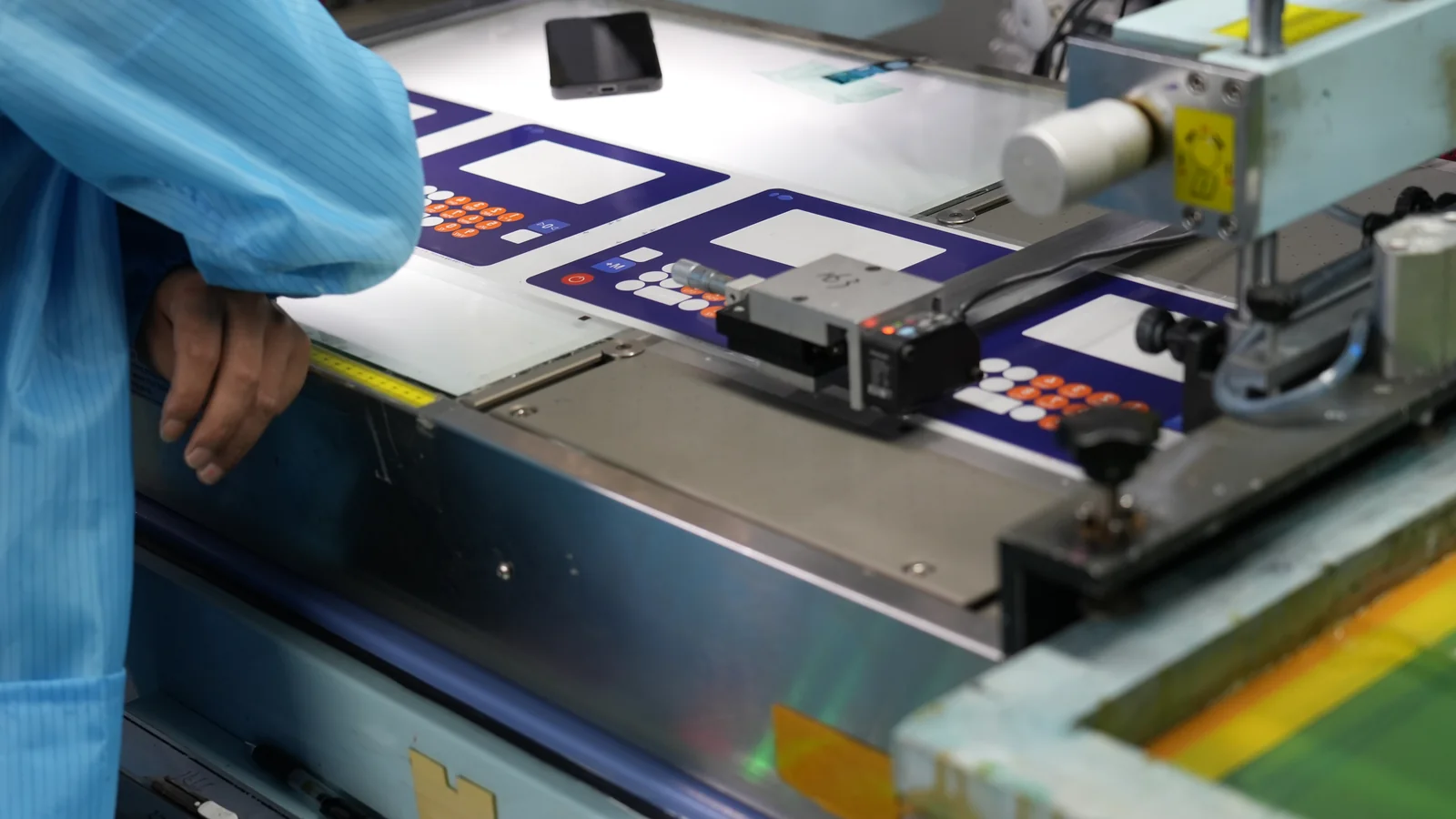
Define the installed boundary before sourcing parts or HMI assemblies.
HMI development at a glance: seven controlled gates
Each phase closes uncertainty before tooling, qualification or production.
| Phase | Decision to close | Controlled output | Gate to advance |
|---|---|---|---|
| 1. User/task study | Who operates, cleans, services and installs—and where? | User/task/use-condition record | Critical tasks and environments agreed |
| 2. Requirements | What must the interface show, accept, withstand and connect? | Traceable requirements | Conflicts and missing limits assigned |
| 3. Architecture | Which display, input, circuit, seal and mounting concept fit together? | Stack and interface allocation | Feasible stack selected |
| 4. Interface freeze | Which geometry, tolerance, pinout and datum controls suppliers? | Released drawings/specifications | Cross-functional sign-off |
| 5. Prototype | Which risk does each sample retire? | Identified samples and discrepancy log | Purpose met; deviations dispositioned |
| 6. Validation | Does a representative assembly meet defined conditions? | Requirement/test matrix and reports | Results accepted; failures resolved |
| 7. Production release | Can the baseline be built, inspected and changed? | BOM, drawings, inspection plan and change baseline | Manufacturing/quality authorization |
What HMI development means for OEM hardware
HMI development defines how a person receives machine information and gives the machine an input. At equipment level, it covers behavior and physical construction: screen layout, viewing window, touch sensor, keys, legends, connector, ground path, seal and mounting geometry. What Is an HMI Panel? Hardware and OEM Guide provides the foundational terminology.
The hardware handoff ends at the agreed interface. The OEM or controls integrator retains application software, PLC/SCADA logic, networks, finished-machine risk controls and regulatory approval. Freezing a pinout does not transfer code ownership.
The International Organization for Standardization’s ISO 9241-210:2019 covers hardware and software contributions across human-centered design. Every interface still needs a named owner.
The sequence iterates until interface freeze:
Users + tasks + use environment
              ↓
      System requirements ↔ risk controls
              ↓
 Display + input + overlay + circuit + enclosure architecture
              ↓
       MECHANICAL / ELECTRICAL / OPTICAL FREEZE
              ↓
 Appearance → fit → functional → production-intent samples
              ↓
        Verification + end-equipment validation
              ↓
     CONTROLLED PRODUCTION RELEASE
              ↺ approved changes return to impact review
Start HMI development with tasks and use conditions
Component selection follows task analysis. In August 2000, the Oak Ridge National Laboratory design guide placed function and task information before conceptual panel layouts. Hardware cannot support an undefined task.
Record operators, setup, cleaning, installation and service users. For each critical task, capture frequency, urgency, error consequence, feedback and hand position.
The use-condition record should cover:
- ambient/enclosure temperature, solar load and condensation;
- indoor/outdoor location, water, dust, oils, coolants and cleaners;
- finger, glove, stylus or tool input, including contamination;
- viewing distance, angle, lighting, glare and required color recognition;
- installed vibration, impact, panel flex and cable movement;
- ESD exposure, noise sources and ground/shield path;
- mounting orientation, available depth, service access and assembly sequence; and
- destination markets, equipment category and the standards or regulations selected by the OEM compliance owner.
These inputs drive control layout. Review HMI Ergonomics and Human Factors for Industrial Equipment because reach, visibility, feedback and error recovery are design inputs, not post-CAD cosmetics.
A requirement needs an owner, condition and acceptance rule. Replace “washdown resistant” with an installed configuration, exposure, method, severity and allowed result. Do the same for readability and input response.
Build the HMI stack as one hardware architecture
A manufacturable architecture treats every layer as one system. Conforming parts can still assemble into a misaligned, bowed, leaking or unstable interface.
Select input against task and environment, not fashion. A 2023 Fraunhofer Institute/Procedia CIRP methodology likewise makes HMI device selection use-case specific.
| Input architecture | Strong fit when | Poor fit when | Hardware implications to freeze | Prototype evidence |
|---|---|---|---|---|
| Projected-capacitive touch | A continuous cover lens, gestures or flexible on-screen controls matter and the selected controller can be tuned for the actual cover and environment | Required gloves, water films, conductive contamination or nearby metal have not been proven with the final stack | Cover material/thickness, sensor, controller, adhesive, bezel ground and display-noise environment | Touch maps and false-touch behavior on the installed stack |
| Resistive touch | Pressure activation, simple single-point input or common glove/stylus use drives the task | Optical clarity, multi-touch gestures or resistance to sharp-object damage dominates | Flexible top layer, edge seal, tail, actuation method and display spacing | Input accuracy, edge behavior and surface durability under specified use |
| Membrane switch or discrete keys | Fixed functions, tactile location, sealed legends or operation without watching the panel is important | Frequently changing functions or dense dynamic menus dominate | Key centers, actuation construction, embossing, circuit, tail, backer and overlay | Force/tactile feel, legend registration, switch matrix and seal continuity |
| Hybrid touch plus physical controls | Dynamic screens are useful but critical or frequent actions need fixed tactile controls | The panel cannot accommodate two interface systems or owners have not defined their interaction | Shared datums, visual hierarchy, ground/shield paths, connectors and software handoff | Cross-input task trials and simultaneous electrical operation |
For capacitive input, the front stack is part of the sensor. Microchip Technology AN2934 (2020) explains how cover thickness changes coupling and sensitivity; Microchip Technology AN3908 (2022) identifies adhesive voids, moisture, conductive decoration, nearby metal and uneven pressure. These are design guides, not guarantees. Test the real stack.
Conceptual stack, front to rear:
Operator side
┌──────────────────────────────────────────────┐
│ Decorated overlay or cover lens             │
├──────────────────────────────────────────────┤
│ Touch sensor and/or membrane key layer      │
├──────────────────────────────────────────────┤
│ Bonding layer, spacer, window and seal      │
├──────────────────────────────────────────────┤
│ Display module and controlled keep-out      │
├──────────────────────────────────────────────┤
│ PCB/FPC, tail, connector, shield and ground │
├──────────────────────────────────────────────┤
│ Carrier, bezel and OEM enclosure datum      │
└──────────────────────────────────────────────┘
Equipment interior
Constructions vary, so the diagram is a checklist, not a mandatory BOM. High-Performance HMI Hardware Design covers related thermal, grounding, optical and mechanical decisions.
Freeze mechanical, electrical and optical interfaces before tooling
Interface freeze is complete when released documents define fit, function and acceptance at every OEM–supplier boundary. A display part number or nominal cutout without datums and tolerances is not a freeze.
Use one coordinate system across the overlay or lens, sensor, display viewing area, mounting features and enclosure. The drawing package should identify:
- external outline, viewing area, active area, key/touch centers and graphic-registration datums;
- enclosure cutout, mounting holes or adhesive land, edge clearances and permitted cosmetic gaps;
- minimum/maximum Z stack, support surfaces, gasket or foam condition and no-pressure regions;
- tail exit, bend and keep-out areas, service loop, connector location and assembly-tool access;
- connector manufacturer/series or controlled equivalent, mating part, keying, lock, pinout and current/voltage ownership;
- display, touch, backlight, ground, shield and chassis interfaces at the defined host boundary;
- cosmetic zones, color/texture master, allowable defects, inspection lighting and viewing condition; and
- part numbers, revision levels, approved materials, marking, traceability and packaging requirements.
The American Society of Mechanical Engineers’ ASME Y14.5-2018 (R2024) supplies a language for dimensional and geometric requirements. The OEM still chooses functional datums and tolerances. Do not tool yet if they are unresolved.
Freeze tolerance chains, not nominal CAD. Check the permitted stack against display load, adhesive contact, seal condition, connector reach and enclosure closure. Record ownership of the display source drawing and revision review. Use the HMI Panel Assembly Design Checklist for cross-functional review.
Mechanical, electrical, design, controls-interface, quality, manufacturing, service and procurement owners sign the freeze. Assign every unresolved item an owner before affected tooling advances.
Use prototypes to retire different HMI risks
A prototype is valid only for represented materials, processes and interfaces. One sample is insufficient. A polished demo may approve appearance while proving nothing about production adhesive, seals or cable strain.
| Sample class | Primary question | Should represent | Does not prove by itself |
|---|---|---|---|
| Appearance model | Does the visual hierarchy, finish and physical scale support the design intent? | Size, graphics, color direction, visible surfaces | Electrical function, production color tolerance or sealing |
| Mechanical fit sample | Do cutout, datums, fasteners, stack depth, tail and service access fit the equipment? | Production-equivalent geometry and mating enclosure | Final input tuning, environmental durability or cosmetic process |
| Functional engineering sample | Do display, input, circuit, connector and host handoff operate together? | Electrical architecture and representative stack materials | Production tooling/process variation unless specifically represented |
| Production-intent sample | Does the released construction from intended tools and processes meet the approval plan? | Released or explicitly deviated parts, tooling, process route and inspection criteria | Finished-machine compliance outside the agreed test scope |
Label samples with part number, revision, build/lot identity and deviations. Approvals name accepted characteristics and open discrepancies. A “golden sample” without configuration identity is weak evidence.
Plan prototyping and sample approval around the largest risk. Build the real touch stack early when input behavior is uncertain; lead with a fit sample when depth and tail routing dominate.
Validate the assembled HMI against traceable requirements
Validation connects every requirement to a representative sample, condition, acceptance rule and record. No single “industrial HMI test” qualifies every design; equipment, installation and risk determine the method and severity.
The standards supply methods or classifications, not automatic requirements. The International Electrotechnical Commission’s IEC 60529 (2013 consolidated edition) classifies enclosure protection. The National Electrical Manufacturers Association’s NEMA 250-2018 covers Enclosure Types; its enclosure FAQ says IP codes do not substitute for U.S. Enclosure Type ratings. A front panel cannot rate the finished machine.
| Requirement area | Representative sample and setup | Method source or input | Acceptance evidence | Common failure path |
|---|---|---|---|---|
| Visual and optical | Final window/lens, display, decoration and installed viewing geometry | OEM luminance, contrast, color, viewing and ambient-light requirements | Recorded readings plus approved visual criteria | Window registration, reflections, mura or bezel shadow appears only after assembly |
| Touch or key input | Final cover/overlay, sensor/keys, controller, display, bezel and ground path | Task cases for gloves, contaminants, edges, multi-touch or tactile feedback | Input map, response log and defined false/missed-input limits | Bench sensor passes; installed metal, noise, water or stack pressure changes behavior |
| Mechanical fit | Tolerance-representative parts in production-equivalent enclosure | Released drawings and stack analysis | Dimensional report, closure/clearance check and discrepancy disposition | Nominals fit but worst-case Z stack loads the display or misses the adhesive land |
| Ingress/seal | Installed panel on defined enclosure surface with production seal and fasteners/adhesive | Applicable IEC 60529, NEMA Type or customer exposure method | Test report tied to configuration and setup | Bare front panel is tested without the actual cutout, seam or cable exit |
| Temperature change | Powered or unpowered state defined by the requirement; final adhesives, display and enclosure | IEC 60068-2-14:2023 when selected | Pre/during/post function, visual inspection and recorded conditions | Differential expansion shifts optics, seal compression or connector seating |
| Vibration | Installed orientation, mounting, cable support and operating state | IEC 60068-2-6:2007 for sinusoidal vibration when applicable | Functional monitoring and post-test mechanical/electrical inspection | Unsupported tail or connector carries movement not represented in component testing |
| ESD immunity | Finished HMI, defined ground/chassis, cable state and accessible points | IEC 61000-4-2:2025 when applicable | Performance criterion, event log and recovery behavior | Decorative or bezel paths couple discharge into touch or logic circuits |
| Cleaning/chemical exposure | Final printed surface, window, adhesive edges and named agents/process | OEM sanitation procedure; material supplier data; selected method | Appearance, adhesion, function and seal observations after defined exposure | A generic “chemical resistant” material is tested with the wrong agent or dwell |
| Circuit, tail and harness | Released circuit, connector, strain relief and production termination | IPC-2221C (2023); IPC/WHMA-A-620E (2022) when selected | Electrical test, pinout and workmanship/retention record | Tail exit or crimp criteria are absent from the package |
| Production inspection | Units from intended materials, tools and process route | Released control plan and agreed sampling/measurement method | First-article or customer-specific approval record and inspection data | Prototype-only checks never become repeatable production controls |
For coating adhesion, name substrate and method. ASTM International D3359-23 (2023) covers relatively ductile coatings on metallic substrates; it is not a universal printed-overlay test.
Separate supplier verification from finished-equipment validation. A supplier may verify a pinout or fixture-test the assembly; the OEM proves intended use and finished-product obligations. Align testing and validation planning before sample build because fixtures and configuration affect the design.
Control HMI changes through production release
Production release creates a baseline and repeatable change path. The International Organization for Standardization’s ISO 10007:2017 covers configuration management from concept through disposal. The baseline must match.
The baseline includes the BOM, drawings, specifications, controlled sources, pinout, approved samples, reports, deviations, inspection plan and responsibilities. All documents agree on revision.
After freeze, route each proposed change through the same questions:
- What component, material, tool, process, drawing or supplier source changes?
- Which user, optical, mechanical, electrical, environmental, cosmetic or regulatory requirements could be affected?
- Is the new item interchangeable at nominal and tolerance limits?
- Which analysis, sample or test must be repeated, and why is any omitted test still covered?
- Who approves the change, which production lot or serial range implements it, and how are mixed configurations prevented or identified?
“Form, fit and function equivalent” is a conclusion, not evidence. A display can retain outline and connector yet change viewing or noise behavior. Record the impact decision and evidence.
Release after discrepancies are closed or accepted, inspection can measure critical characteristics and procurement controls sources. Use customer-specific first-article or production-part approval evidence when required; a generic sample package is not PPAP.
Common failure paths—and when a custom HMI is not suitable
Common failures sit at interfaces: graphics miss sensor/key centers, a cutout precedes the display drawing, a gasket lacks a controlled land, cable routing ignores service movement, or component results are applied to the assembly. Hardware and software teams also drift when coordinate systems, pin names or revisions differ.
Custom hardware is not always right. Use a standard panel when it meets installation, input and lifecycle requirements. Resolve unstable host, enclosure, task or compliance architecture first. Safety functions need evaluated devices; software labels do not make a touchscreen safety rated. Medical-device teams should apply the U.S. Food and Drug Administration’s August 2026 human-factors guidance to intended users, uses and use environments.
Project-input checklist for an HMI hardware review
Send a controlled package, not only a product photo and screen size:
- display part number or active area, resolution and host interface;
- front-panel/enclosure drawings with cutout, datums, depth and mounts;
- stack, input, tail/connector/pinout and ground/shield concept;
- users, critical tasks, glove/stylus, viewing and feedback needs;
- environment, cleaning process, ingress target and validation methods;
- prototype stages, acceptance criteria, market and equipment requirements; and
- prototype quantity, annual volume, service life and change-notification needs.
Teams can send drawings for engineering review with the display size, front-panel drawing, interface stack, environment and annual volume. If the baseline is ready for sourcing, request an engineering quote for the defined HMI hardware assembly.
Frequently asked questions about HMI development
What is HMI development for OEM equipment?
HMI development is the controlled process of turning operator tasks and equipment requirements into the physical and behavioral interface between a person and a machine. For an OEM hardware assembly, it covers the front panel, display, input layer, circuit, connector, sealing and enclosure interfaces, plus the evidence needed for release.
What information is needed before HMI hardware development starts?
Start with intended users and tasks, equipment and front-panel drawings, display or active-area requirements, available depth, input method, host interface, environment, cleaning process, viewing conditions, applicable standards, acceptance criteria, prototype needs and annual volume. Unknowns should be logged with owners rather than hidden inside a supplier assumption.
When should an OEM freeze the display, touch and enclosure interfaces?
Freeze them after the selected parts fit one controlled mechanical, electrical and optical stack at tolerance limits. The drawings should define datums, viewing and active areas, Z stack, keep-outs, seal land, tail route, connector and pinout, ground/shield path and acceptance criteria. Freeze before affected production tooling and qualification samples.
Does HMI development include PLC or SCADA programming?
HMI development can include software in its broad industry meaning, but JASPER’s front-panel manufacturing scope does not include PLC/SCADA programming. The hardware package can define display, touch, switch, connector, pinout and host-interface boundaries; the OEM or controls integrator owns application logic and finished-machine behavior unless separately contracted.
Which input technology is best for an industrial HMI?
No input technology is best for every industrial HMI. Projected-capacitive touch fits continuous covers and dynamic controls when the final stack is tuned for gloves, water and noise. Resistive touch supports pressure input. Membrane or discrete keys suit fixed tactile actions. Hybrid panels combine dynamic screens with dedicated physical controls.
What should an HMI prototype prove before sample approval?
The approval must match the sample’s purpose. An appearance model can approve scale and visual direction; a fit sample checks enclosure interfaces; a functional sample checks display, input and host handoff; a production-intent sample evaluates released materials, tooling and processes. Record configuration, deviations, evidence reviewed and unresolved discrepancies.
Which tests are required for an OEM HMI assembly?
Required tests come from the end-equipment specification, risk analysis, installation and destination market. Typical requirement areas include visual performance, input behavior, fit, sealing, temperature, vibration, ESD, cleaning exposure, circuits and connectors. Each test needs a representative sample, defined setup and severity, acceptance rule and retained result; no generic list qualifies every HMI.
How should HMI hardware changes be controlled after interface freeze?
Identify the changed part, material, tool, process, drawing or source; review every affected user, optical, mechanical, electrical, environmental and regulatory requirement; then document interchangeability, required samples or repeated tests, approvals and implementation traceability. A supplier’s “equivalent” statement does not replace OEM impact review or a revalidation decision.
References
- ISO 9241-210:2019 — Human-centred design for interactive systems, International Organization for Standardization, 2019.
- Remote Maintenance Design Guide for Compact Processing Units, ORNL/TM-2000/124, Oak Ridge National Laboratory, August 2000.
- A Methodology for the Systematic Selection of Human-Machine Interface Device Types, Procedia CIRP / Fraunhofer IPA, 2023.
- IEC 60529 — Degrees of protection provided by enclosures, International Electrotechnical Commission, consolidated edition 2013.
- NEMA 250 — Enclosures for Electrical Equipment, contents and scope, National Electrical Manufacturers Association, 2018.
- NEMA Enclosures FAQ, National Electrical Manufacturers Association.
- IEC 61000-4-2:2025 — Electrostatic discharge immunity test, International Electrotechnical Commission, 2025.
- IEC 60068-2-6:2007 — Sinusoidal vibration, International Electrotechnical Commission, 2007.
- IEC 60068-2-14:2023 — Change of temperature, International Electrotechnical Commission, 2023.
- IPC document revision table, including IPC-2221C (2023) and IPC/WHMA-A-620E (2022).
- Microchip Technology AN2934 — Capacitive Touch Sensor Design, July 2020.
- Microchip Technology AN3908 — maXTouch Sensor Design Guide, August 2022.
- ASME Y14.5 — Dimensioning and Tolerancing, 2018 edition, reaffirmed 2024.
- ISO 10007:2017 — Guidelines for configuration management, confirmed 2023.
- ASTM D3359-23 — Rating Adhesion by Tape Test, ASTM International, 2023.
- FDA human factors guidance for medical devices, August 2026.
Bring the drawing, stack and operating conditions
JASPER engineering will review the interfaces, open risks and evidence required for a production quote.