
High-performance HMI hardware is a front-panel assembly engineered so the intended operator can see machine state, recognize an abnormal condition, choose the correct control, and confirm the result under the specified lighting, contamination, glove, and viewing conditions. It applies to OEM teams integrating displays, touch sensors, overlays, switches, indicators, circuits, adhesives, seals, connectors, and enclosures. The practical recommendation is to specify the complete response path, then validate the assembled panel—not isolated components. For custom HMI assemblies, the decisive variables are visibility, information hierarchy, input method, feedback, response timing, environmental exposure, mechanical stack-up, and degraded-state behavior.
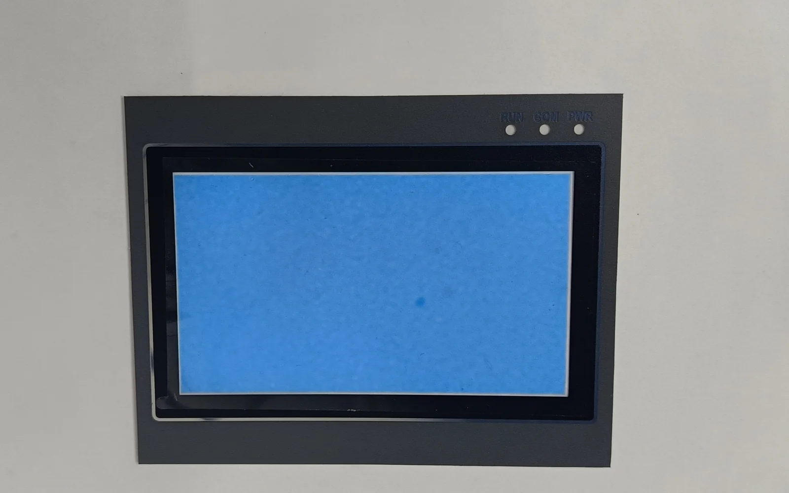
Quick decision table: translate operator goals into hardware evidence
| Operator objective | Hardware decision | Drawing or RFQ input | Acceptance evidence |
|---|---|---|---|
| See normal state without searching | Display size, active area, window finish, bezel geometry, character/symbol size | Viewing distance and angle, ambient illumination, required information zones | Readability review on the production-intent stack at minimum and maximum lighting |
| Notice an abnormal state | Reserved color, contrast, dedicated indicator, audible/tactile backup | Alarm classes, required redundant cues, failed-display response | Normal/abnormal state matrix, indicator test, simulated loss of one cue |
| Select the correct action | Touch technology, target geometry, tactile separation, guard/recess | Glove, stylus, wet-hand condition, critical-control list | Task test with intended users and accessories; false/missed-input log |
| Confirm that input was accepted | Local visual, tactile, or audible feedback and host acknowledgment | End-to-end timing point definitions and timeout behavior | Timestamped measurement from physical actuation to visible or physical confirmation |
| Survive the use environment | Overlay, lens, adhesive, gasket, vent, flex, connector, enclosure joint | Chemicals, temperature/humidity, ingress target, ESD/EMC environment, cleaning method | Assembly-level environmental, ingress, electrical, and cycling reports |
High performance HMI starts with operator performance, not processor speed
A high performance HMI organizes information and controls around operator tasks and abnormal-response needs. Processor throughput, frame rate, and memory bandwidth may constrain the implementation, but they do not define whether an operator can recognize and act correctly. The ISA-101 series frames HMI work as a lifecycle covering design, implementation, operation, and maintenance; the official scope includes display structures, interaction, and usability across continuous, batch, and discrete industries.
For hardware teams, the philosophy becomes physical requirements. A calm screen fails under glare; color-only alarms fail under washout. A fast touch controller cannot compensate for delay in the host, application, display refresh, indicator circuit, or operator feedback.
An HMI is more than the screen. What Is an HMI Panel? Hardware and OEM Guide covers its surfaces, inputs, outputs, circuits, mechanical interfaces, and protective boundary. PLC logic, SCADA programming, alarm rationalization, and network configuration remain outside panel manufacturing, although their signal definitions and timing budgets are required inputs.
The canonical HMI anatomy is a closed operator-response path
High-performance hardware links an operator action to unambiguous feedback through a stack whose optical, mechanical, electrical, and environmental interfaces are designed together.
  OPERATOR TASK AND ABNORMAL-RESPONSE NEED
                 │
      viewing angle • ambient light • glove • reach
                 ▼
  COVER LENS / GRAPHIC OVERLAY / DISPLAY WINDOW
                 │
        touch sensor or tactile switch layer
                 ▼
  PRINTED CIRCUIT / FLEX TAIL / CONNECTOR / CONTROLLER
                 │
       host command and equipment-state signal
                 ▼
  DISPLAY PIXELS + STATUS LED + TACTILE/AUDIBLE FEEDBACK
                 │
                 └──────── confirmation to operator

  Assembly boundary: bezel + adhesive + gasket + fasteners +
  enclosure cutout + grounding/shielding + service access
Figure 1. Canonical high-performance HMI hardware response path. The surface stack, input circuit, host interface, feedback devices, and enclosure boundary must remain traceable to one operator task. The drawing should identify active and viewable areas, dead zones, adhesive lands, gasket compression region, tail exit, bend keep-outs, connector datum, indicator light path, bezel overlap, and service-removal direction.
Layer order varies. A display-touch assembly may use a cover lens, bond, touch sensor, display, carrier, and sealed bezel. A membrane-switch hybrid may add a reverse-printed overlay, domes or contacts, flexible circuit, backlighting, rear adhesive, and a rigid backer. Either architecture must preserve the response path and protection boundary across production tolerances.
Visibility depends on the installed optical path and viewing envelope
Display selection should start with what must be readable, from where, and under which illumination—not with diagonal size alone. ISO 9241-303:2011 establishes technology-independent image-quality requirements for effective and comfortable viewing. An OEM specification should therefore define viewing distance, horizontal and vertical angle, ambient-light range and direction, operator posture, required text and symbol zones, normal/abnormal contrast states, and window surface finish.
The panel stack can change the module-level result. A textured overlay may diffuse reflections but also soften fine detail. A glossy clear window can preserve sharpness while reflecting overhead luminaires. A deep bezel can shade the display from one direction and block it from another. Printed borders, adhesive squeeze, lens tint, air gaps, touch electrodes, polarizers, condensation, and protective films all affect the optical path.
Reserve the most visible region for equipment state and actionable deviation; keep navigation, maintenance data, and decoration from competing with it. Validate the actual fonts, icons, trends, and alarms on production-intent hardware. HMI Ergonomics and Human Factors for Industrial Equipment covers broader placement questions, but the panel drawing must carry the resulting sightline and reach constraints.
Alarm indication needs a visible state and a credible fallback
Alarm hardware should make the abnormal condition identifiable without asking the operator to decode color alone. IEC 62682:2022 defines the alarm system’s role as notifying operators of abnormal process conditions or equipment malfunctions and supporting response; it also recognizes presentation through an HMI or annunciator. Alarm generation and prioritization belong to the control-system owner. The panel supplier needs the resulting state table, signal polarity, feedback rules, and loss-of-communication behavior.
IEC 60073:2002 establishes general coding principles for visual, acoustic, and tactile indications. In hardware terms, redundancy can pair color with text, icon shape, position, flash pattern, an illuminated legend, a buzzer, or tactile differentiation. The team must define which combinations are permitted for each state and what occurs if one modality fails.
A dedicated lamp is not automatically safer than a screen icon. Verify its off-state appearance, bright-ambient legibility, viewing angle, leakage into adjacent legends, dimming, and test function. For a critical function, document whether loss of display, backlight, touch, communication, or indicator power leaves a detectable fault and usable alternate action. Map product obligations through Industrial HMI Standards and Hardware Compliance; ISA-101 is not a panel certification.
Touch and tactile controls must be specified as an end-to-end response
Touch technology changes the physical failure modes. A projected-capacitive (PCAP) design senses through a dielectric cover, so lens thickness, sensor geometry, grounding, display noise, glove material, moisture, and firmware tuning interact. Microchip’s AN3908 sensor design guide shows that electrode topology, layer count, electrode pitch, PET/glass construction, channel count, shielding, glove support, and stylus support cannot be chosen independently.
Supplier limits must stay attached to their conditions. The Microchip mXT1665TD Rev. B datasheet, for example, lists bare-finger operation through 10 mm glass or 5 mm PMMA and multi-finger operation with a 5 mm glove through 6 mm glass or 3 mm PMMA. It also documents water-drop conditions up to 22 mm diameter and a typical ten-touch report rate of at least 100 Hz, all subject to screen size, configuration, and stack-up. Those figures are not generic PCAP specifications, and a 100 Hz report rate is not a 10 ms equipment-response guarantee.
A resistive screen uses separated conductive layers that make contact under pressure; Microchip’s AVR341 application note describes the PET top membrane, rigid substrate, ITO layers, spacers, and four-wire interface. The pressure-driven mechanism may suit an intended stylus or glove workflow, but optical transmission, membrane wear, edge sealing, calibration, and the required force still need product-specific evidence.
Membrane switches and hard keys provide physical travel or snap feedback when designed for it. They can reserve stop, reset, acknowledge, or jog functions outside the touchscreen, yet their force, spacing, guard geometry, contact behavior, debounce, electrical load, and cycle requirement must be written down. Do not ask for “good tactile feel.” Specify the force-displacement acceptance window, measurement fixture, actuator geometry, operating temperature, electrical threshold, sample count, and after-conditioning limits.
Measure response at defined endpoints: physical contact or switch closure; controller event; host acceptance; equipment-state transition; and visible, tactile, or audible confirmation. Log each segment under normal load and credible degraded conditions. This separates input-device latency from software, network, control, and display delays without moving PLC/SCADA programming into the hardware supplier’s scope.
Lighting, overlays, adhesives, and enclosure joints form one assembly
Backlighting should reinforce hierarchy. Specify off-state legend visibility, permitted flashing or intensity changes, uniformity boundaries, dimming range, color tolerance, light leakage, thermal rise, and failed-light behavior. Shared light guides can couple adjacent legends; discrete LEDs add circuit, thermal, and alignment constraints.
Overlay material is a functional layer. As a bounded example, the MacDermid Alpha Autotex technical data sheet lists hard-coated PET in 150, 200, and 280 µm gauges with defined finish and primer variants. Those gauges show why material name alone is incomplete: thickness affects embossing, tactile response, optical window construction, die cutting, and stack tolerance. Chemical exposure must be matched to the actual cleaner, concentration, dwell, wiping method, and frequency.
Adhesive selection has the same boundary. 3M’s 200MP technical data lists 467MP and 468MP adhesive constructions at 0.06 mm and 0.13 mm nominal thickness, respectively. That is product-specific data, not permission to substitute either tape into every enclosure. Surface energy, texture, flatness, paint or powder coat, contamination, bond-line stress, temperature, humidity, chemical exposure, dwell, and assembly pressure determine the application result.
Ingress performance belongs to the assembled boundary. IEC 60529 defines enclosure IP degrees; it does not turn an uninstalled overlay, display, or gasket into a rated enclosure. NEMA’s Technical Bulletin 123 explains, for its conduit/fitting/enclosure example, that system capability is limited by the lowest-rated component and that NEMA Type and IP ratings are not completely equivalent. For an HMI, test the panel, gasket, cutout, fasteners, cable exits, vents, and enclosure interface in their production-intent configuration.
HMI hardware variants solve different response and environment problems
| Variant | Best fit | Hardware advantage | Limitation that must be accepted or mitigated |
|---|---|---|---|
| PCAP display assembly | Multi-touch, gesture, and optically continuous interfaces | Sensing through a cover lens; flexible surface design | Stack-up, grounding, noise, glove, water, and tuning are interdependent |
| Resistive touch display | Pressure or stylus input with simple coordinate sensing | Direct pressure closes the sensor stack | Flexible top layer, optical loss, calibration, wear, and edge sealing require validation |
| Display plus membrane keys | Dynamic information with frequently used physical controls | Separates critical or repetitive actions from screen navigation | Larger bezel area; overlay, dome, light, and flex tolerances interact |
| Hard keys plus dedicated indicators | Fixed tasks, harsh use, or required fallback control | Strong physical differentiation and direct state indication | Limited reconfiguration; more penetrations, wiring, and sealing interfaces |
| Display-only panel | Monitoring where no local command is required | Simpler input boundary | Unsuitable when local acknowledgment, recovery, or manual control is required |
A touchscreen-only advanced HMI is a poor choice when the operator cannot reliably view or touch the screen, must actuate a control without looking, needs a credible action after display failure, or wears equipment that has not been qualified with the chosen sensor. A colorful display is also unsuitable as the sole alarm channel when color discrimination, ambient light, obstruction, or backlight loss can hide the state.
Failure-path design should expose faults instead of hiding them
The useful question is not “Which component is reliable?” but “What will the operator observe when this interface fails?”
| Failure domain | Credible failure path | Required design output |
|---|---|---|
| Optical | Glare, condensation, window haze, backlight loss, dead pixels, bezel obstruction, shifted overlay | Detectable fault, preserved critical indication, defined service action |
| Input | Missed/false touch, stuck key, contact bounce, drift, glove mismatch, water film, adjacent activation | Input filtering and feedback rules, alternate action, fault test |
| Interconnect | Flex crack, excessive bend, connector back-out, fretting, contamination, poor strain relief | Routing limits, retention, diagnostic behavior, inspection method |
| Mechanical/environmental | Adhesive lift, lost gasket compression, housing distortion, chemical attack, differential expansion | Controlled bond/seal design and assembly-level conditioning |
| System | Host or communication loss, stale data, lost acknowledgment, delayed feedback | Visible degraded state, timeout, recovery, alternate control |
Define the safe visible state, diagnostic signal, alternate control, service action, and acceptance test for each relevant fault. The 2026 U.S. NRC NUREG-0700 Revision 4 is nuclear-sector guidance, not a general industrial compliance standard, but its review categories—information displays, interaction, controls, alarms, workstations, maintainability, degraded interfaces, and resource integration—provide a disciplined checklist for identifying omitted response paths.
Validation must use the production-intent stack and named conditions
Validation should connect every operator or environmental requirement to a specimen, method, condition, measurement, and pass/fail rule. The HMI Panel Assembly Design Checklist helps coordinate mechanical inputs; detailed testing and validation planning should then assign ownership and evidence.
| Validation item | Production-intent conditions | Record |
|---|---|---|
| Visibility and hierarchy | Minimum/maximum ambient light, specified distance/angles, all normal and abnormal screens, clean and expected contaminated states | Photos or measurements tied to setup; task/readability results |
| Touch and hard controls | Named glove/stylus, dry/wet/cleaner residue, target locations including edges, temperature limits | False, missed, adjacent, and repeated input results; force-displacement data where applicable |
| Response and feedback | Defined event endpoints, normal load, startup, communications loss, degraded feedback device | Timestamp trace and timeout/recovery behavior |
| Indicators and backlight | Bright/dim ambient, dimming limits, off/on/alarm states, adjacent legends, failed lamp/backlight | State matrix, uniformity/leakage observations, fault indication |
| Ingress and chemicals | Assembled panel/enclosure, specified mounting and gasket, named liquid/cleaner, concentration, dwell, pressure/direction if applicable | Method, specimen configuration, pre/post functional and visual checks |
| Temperature and humidity | Defined operating/storage profiles and ramp/dwell, powered state, condensation expectation | Functional, optical, bond, seal, and electrical results before/during/after |
| ESD/EMC and grounding | Final cable, shield, enclosure, power supply, grounding, display/touch configuration | Applied levels/methods, performance criteria, resets, false inputs, recovery |
| Flex, connector, and service | Minimum bend radius, bend count, pull/retention, mating cycles, removal path | Continuity, resistance, retention, inspection, post-service function |
| Switch cycling | Production actuator geometry, force, rate, electrical load, environment, predetermined count | Circuit resistance and tactile/visual condition before, during, and after cycling |
For membrane switches, ASTM F1578-24 defines cycling to a predetermined count and permits specified voltage and current during the test. It does not provide a universal life target. The OEM must set the count and electrical/environmental conditions from the use profile, then state acceptable change in circuit and physical behavior.
Use prototyping and sample approval to freeze more than appearance. Approve the bill of materials, revision, print colors and opacity, display/touch configuration, force profile, LED behavior, adhesive/gasket stack, flex routing, connector, firmware/configuration identifier where relevant, test fixtures, and golden-sample limits. Any later substitution that can change the response path requires controlled review.
Project-input checklist for a manufacturable HMI assembly
Provide these inputs before design release:
- front-panel drawing with cutout, datums, thickness, flatness, finish, fasteners, and available rear volume;
- display model/size, active and viewable areas, orientation, interface, brightness control, and service strategy;
- touch or switch technology, target geometry, glove/stylus/wet-use requirements, critical hard keys, feedback, and response endpoints;
- overlay/lens material, windows, texture, colors, legends, embossing, indicator map, cleaning chemicals, and cosmetic limits;
- circuit schematic or matrix, pinout, flex exit, bend limits, connector, shielding/grounding, electrical loads, and debounce ownership;
- environmental and compliance inputs: operating/storage profiles, ingress boundary, ESD/EMC context, impact/vibration needs, and applicable product standards;
- validation quantities, sample-approval rules, change control, annual volume, packaging, and traceability needs.
When these inputs are ready, send drawings for engineering review. Include the display size, front-panel drawing, complete interface stack, operating environment, and annual volume so the assembly boundary can be reviewed before tooling or qualification.
Frequently asked questions
What is a high performance HMI in hardware terms?
A high performance HMI is a front-panel system that lets the intended operator detect state, recognize abnormalities, act correctly, and confirm the result under defined use conditions. Its hardware includes the display, touch or switches, overlay, lighting, circuit, interconnect, bonding, sealing, and enclosure interfaces—not merely a fast processor or attractive screen.
Does ISA-101 specify the physical HMI panel construction?
ISA-101 provides a lifecycle and design framework for process-automation HMIs, including display structure, interaction, navigation, graphics, and alarming. It does not by itself specify a cover lens, adhesive, gasket, circuit, connector, enclosure rating, or finished-panel test plan. Product and market requirements must supply those hardware obligations.
Is PCAP or resistive touch better for an industrial HMI?
Neither is universally better. PCAP suits multi-touch and continuous cover-lens designs when its stack, grounding, noise, glove, and moisture behavior are qualified. Resistive touch suits pressure-based finger or stylus input but introduces a flexible contact stack, optical and wear considerations, edge sealing, and calibration. Test the intended operator and environment.
Should an emergency stop be placed on the touchscreen?
A touchscreen should not be assumed to satisfy an emergency-stop function. The applicable machinery safety architecture and product standards determine the required device, circuit, actuation, reset, diagnostics, and independence. Give the HMI supplier the resulting physical layout and interface requirements; do not infer safety compliance from screen graphics or ISA-101 alignment.
How should HMI response time be specified?
Define the endpoints and budget each segment: physical contact or switch closure, controller event, host acceptance, equipment-state change, and visible, tactile, or audible confirmation. Measure the complete path under normal and degraded conditions. Touch-controller report rate, display refresh rate, and PLC scan time are inputs, not substitutes for end-to-end evidence.
Does an IP-rated component make the completed HMI IP rated?
No. IEC 60529 applies to enclosure protection, so the production-intent assembly boundary must be evaluated. The lens or overlay, adhesive, gasket, cutout, fasteners, cable exits, vents, and enclosure can each limit performance. Record the exact installed configuration and test method; do not transfer a loose component rating to the finished panel.
What should be approved on an HMI prototype?
Approve the controlled bill of materials and revision, optical appearance, touch behavior, tactile force profile, legends and lighting states, adhesive/gasket stack, flex routing, connector and pinout, configuration identifiers, environmental test setup, and measurable acceptance limits. A cosmetic “golden sample” alone cannot control electrical, optical, or sealing performance.
What information should an OEM include in an HMI RFQ?
Include the display size and model, front-panel and enclosure drawings, touch/switch and electrical interfaces, viewing and operator conditions, overlay/lens artwork, feedback and alarm state tables, environment and cleaning agents, applicable standards, validation plan, annual volume, sample-approval rules, change control, packaging, and traceability requirements.
References
- International Society of Automation. ISA-101 Series of Standards: official scope summaries for ISA-101.01-2015, ISA-TR101.01-2022, and ISA-TR101.02-2019.
- International Electrotechnical Commission. IEC 62682:2022, Management of alarm systems for the process industries.
- International Electrotechnical Commission. IEC 60073:2002, Coding principles for indicators and actuators.
- International Organization for Standardization. ISO 9241-303:2011, Requirements for electronic visual displays; confirmed 2022.
- International Organization for Standardization. ISO 9241-110:2020, Interaction principles; confirmed 2025.
- U.S. Nuclear Regulatory Commission. NUREG-0700, Revision 4, Human-System Interface Design Review Guidelines. Published January 2026.
- International Electrotechnical Commission. IEC 60529, Degrees of protection provided by enclosures (IP Code), consolidated edition 2.2.
- National Electrical Manufacturers Association. Technical Bulletin 123, NEMA and IP Ratings for Liquid-tight Flexible Metal Conduit and Fittings. Approved March 8, 2023.
- Microchip Technology. mXT1665TD Touchscreen Controller Product Datasheet, Revision B; AN3908 maXTouch Sensor Design Guide; and AVR341 Four and Five-Wire Touch Screen Controller.
- MacDermid Alpha. AUTOTEX Textured Hardcoated Polyester Film Technical Data Sheet CPI-00033/8. Issued January 4, 2023.
- 3M. High Performance Adhesive Transfer Tapes with Adhesive 200MP and 467MP Technical Data Sheet.
- ASTM International. ASTM F1578-24, Standard Test Method for Contact Closure Cycling of a Membrane Switch.
JASPER manufactures HMI and front-panel assemblies. This guide separates public technical evidence from project-specific engineering; it does not claim that any untested assembly, material combination, or design is certified for a particular application.
For an engineering and manufacturability review, request an engineering quote with the display size, front-panel drawing, interface stack, environment, and annual volume.
Bring the drawing, stack and operating conditions
JASPER engineering will review the interfaces, open risks and evidence required for a production quote.