
Compare Ag/AgCl vs carbon electrodes by role, polarization, process, substrate, cost drivers, and validation for medical and biosensor circuits.
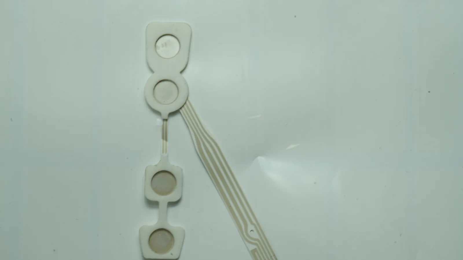
1. Quick Verdict: Select the Ink by Electrode Role
No universal winner exists because Ag/AgCl and carbon perform different electrochemical jobs. A silver silver chloride electrode exchanges charge through the Ag/AgCl/Cl− equilibrium, which is useful at a reference or ionic-to-electronic interface. A screen printed carbon electrode supplies a tailorable surface for oxidation, reduction, immobilized enzymes, mediators, catalysts, or recognition layers.
| Circuit position or requirement | Start evaluation with | Why | Main qualification |
|---|---|---|---|
| ECG-style biopotential contact with conductive gel | Ag/AgCl interface | Designed to limit polarization at the ionic/electronic interface | Test the complete electrode/gel/adhesive assembly; material choice alone does not meet ANSI/AAMI EC12 |
| Electrochemical working electrode | Carbon formulated for the method | Surface chemistry and modification can be tuned for the analyte reaction | Measure background current, usable potential window, electron-transfer behavior, fouling, and lot variation |
| Counter electrode | Carbon in many disposable cells | Can provide adequate area and current capacity without making it the sensing surface | Confirm counter area, current density, and absence of limiting polarization |
| Bare printed pseudo-reference in a controlled chloride matrix | Ag/AgCl | More defined redox couple than an unqualified carbon surface | Characterize chloride dependence, drift, conditioning, and calibration |
| True printed reference across changing samples | Ag/AgCl plus internal chloride reservoir and junction | The reservoir and junction isolate the reference chemistry from sample variation | Validate junction potential, leaching, dry-out, storage, and required duration |
| Low-cost, short, calibrated assay in one controlled matrix | Carbon pseudo-reference may be evaluated | Can remove silver from that circuit position | Not a drop-in substitute; establish potential shift and method bias experimentally |
| Conductive trace | Silver, carbon, or a layered design | Trace resistance, exposed chemistry, area, and cost drive the choice | Keep the trace decision separate from the exposed electrode-interface decision |
The practical answer is often carbon working and counter electrodes plus an Ag/AgCl reference, with silver or carbon traces under a dielectric. Idegami et al. Reported that architecture in a disposable sensor strip, while Shitanda et al. Later demonstrated another fully printed carbon-working/carbon-counter/Ag/AgCl-reference system.^1
2. What Ag/AgCl and Carbon Actually Do
Ag/AgCl is an electrochemical couple, not just a conductive silver ink
At an Ag/AgCl element, the relevant reduction half-reaction is:
AgCl(s) + e− ⇌ Ag(s) + Cl−(aq)
The equilibrium potential therefore changes with chloride activity. At 25°C, the ideal Nernst slope has a magnitude near 59.16 mV for each tenfold change in chloride activity. Erlenkötter et al. Measured about 54.7 mV per decade for the screen-printed pseudo-reference in their flexible three-electrode system. That result is close to Nernstian behavior, but it is not permission to assign the same slope to every printed ink, binder, film thickness, or sample.
This distinction creates two different products that are often called “Ag/AgCl reference electrodes”:
- A pseudo-reference or quasi-reference exposes the printed Ag/AgCl material directly to the sample. Its potential can move with chloride activity, interfering species, conditioning, and surface history.
- A true reference construction adds a controlled chloride electrolyte and a liquid junction or diffusion barrier. Dawkins et al. Used a KCl–poly(vinyl acetate) electrolyte and PDMS junction; that particular device held approximately −45.5 ± 3 mV versus SCE for up to 27 days. The duration belongs to that construction, not to Ag/AgCl ink as a material class.
Carbon is an engineered composite surface, not one fixed electrode material
A carbon ink combines graphite or another carbon phase with binder, solvent, and additives. The cured composite must conduct through the film and transfer electrons at its exposed surface. Those are related but different properties.
- Sheet resistance describes lateral charge transport through a film of defined thickness.
- Interfacial electron-transfer kinetics describe charge transfer between the electrode surface and a redox species.
- Electrochemical potential window describes the usable potential region for a defined electrolyte, pH, reference electrode, surface condition, and current criterion.
A low sheet-resistance number does not prove low background current, fast heterogeneous electron transfer, resistance to fouling, or compatibility with an enzyme layer. Comparative work by Barich et al. In 2024 found that commercial carbon-ink formulation affected resistance, surface properties, electrochemical response, and sensing behavior. Earlier work by Washe et al. Showed how nonelectroactive ink components can mask graphitic sites and how surface treatment can change charge-transfer behavior.
Polarization means different things in different circuit positions
A recording electrode should not develop a large voltage when a small current passes across the interface. A reference electrode should hold a sufficiently stable potential while drawing negligible current. A counter electrode is intentionally polarized to carry the cell current. A working electrode is driven to a potential that supports the target reaction.
Calling one material “low polarization” without naming the circuit position, electrolyte, current, time, area, and test method is incomplete. Medical electrode ink selection starts with the electrode’s function in the equivalent circuit, not with the lowest value in a conductivity table.
3. Ag/AgCl vs Carbon Electrodes: Side-by-Side Engineering Comparison
The table below compares material families under stated roles. The numerical examples are current supplier-sheet values for named formulations; they illustrate the range and cannot be transferred to another grade.
| Dimension | Printed Ag/AgCl | Printed carbon | Engineering consequence |
|---|---|---|---|
| Typical role | Biopotential contact; pseudo-reference; reference/counter in some sensor designs | Working electrode; counter electrode; resistive or protective overprint; calibrated pseudo-reference in selected designs | Compare by circuit position, not by one overall rank |
| Governing interface | Ag/AgCl/Cl− equilibrium | Carbon surface, binder, modifier, electrolyte, and target redox couple | Ag/AgCl is chloride-sensitive; carbon response is formulation- and surface-sensitive |
| Bulk conductivity example | DuPont 5874: 70–90 mΩ/sq/mil, 65:35 Ag:AgCl | DuPont BQ242: 20–25 Ω/sq/mil; BQ221: <100 mΩ/sq/mil | Even carbon grades differ sharply; sheet resistance is not a sensing-performance score |
| Surface modification | Possible, but not the normal reason to select the Ag/AgCl interface | Common route for enzymes, mediators, catalysts, nanoparticles, membranes, or pretreatment | Carbon usually wins where the working surface must be engineered |
| Reference behavior | Bare pseudo-reference follows sample chemistry; reservoir/junction designs can reduce matrix dependence | Potential depends on surface and matrix; useful only where the full method is calibrated and validated | Choose the reference architecture before choosing the paste |
| Print substrate example | DuPont 5874 specifies print-treated polyester | BQ221 specifies PET and polycarbonate; other grades target flexible or stretchable films | Confirm the exact ink/substrate pair, not merely “PET-compatible” |
| Cure example | DuPont 5874: 120°C, 1–2 min conveyor or 3–5 min box oven | DuPont BQ242: 130°C, 5–15 min box oven | A mixed stack needs a shared thermal and solvent budget |
| Cost drivers | Silver content, AgCl ratio, coverage, dry-film thickness, scrap, print passes | Carbon grade, modifier package, coverage, activation, geometry, yield | Carbon powder may cost less, but total stack cost depends on process and validation |
| Primary failure concerns | Chloride-driven potential shift, Ag/AgCl depletion, junction dry-out, chemistry interaction, exposed silver species | Binder-covered active sites, resistance, cracking, fouling, modifier loss, lot variation | Build separate failure tests for each material role |
DuPont 5874 is documented for printing over DuPont 5000/5025 silver conductors or 7102 carbon on print-treated polyester. DuPont BQ221 is explicitly described as a working-electrode composition for high-sensitivity biosensors on PET and polycarbonate, while BQ242 is specified for amperometric carbon working electrodes on polyester.^8 These examples show why an OEM should approve a named ink stack and cure schedule rather than approve only the words “Ag/AgCl” or “carbon.”
4. Where Ag/AgCl Wins—and Where It Does Not
Ag/AgCl is the stronger starting point for many biopotential interfaces
For wet ECG-style electrodes, the exposed interface converts ionic conduction in a gel or body-contact medium into electronic conduction in the printed circuit. Ag/AgCl is commonly selected because its reversible chloride reaction can limit interface polarization under the defined conditions. Rattfält et al. Tested printed Ag/AgCl contact surfaces over carbon or silver conductors on PET. Their electrochemical-cell experiment reported potential drift below 3 mV over 30 minutes, while carbon-backed constructions showed higher resistance at 2 kHz than silver-backed ones.
That study separates two decisions: use Ag/AgCl at the exposed contact and select carbon or silver beneath it as a conductor. It does not establish wear time, clinical signal quality, shelf life, or ANSI/AAMI EC12 conformity for another assembly.
Ag/AgCl is the stronger reference candidate when potential definition matters
A potentiometric or amperometric method needs a reference against which the working-electrode potential is controlled. Ag/AgCl supplies a named equilibrium, so its sensitivities can be modeled and tested. A carbon surface does not automatically provide the same defined relationship.
The recommendation changes when sample chloride varies. A bare printed Ag/AgCl pseudo-reference then follows that variation. If the resulting voltage shift consumes too much of the method’s error budget, the design may need an immobilized chloride reservoir, junction, calibration architecture, or different reference construction. “Printed Ag/AgCl” by itself does not answer that systems question.
Ag/AgCl is not the best choice for every exposed biochemical neighborhood
Ag/AgCl should not automatically share a small wetted volume with a sensitive biological reagent. Lansdorp, Lamberg, and Hamid reported in 2023 that exposure to their screen-printed Ag/AgCl electrode reduced alcohol oxidase activity half-life from nearly one week in buffer to roughly 10 hours. The study does not condemn every Ag/AgCl ink or enzyme. It establishes a design rule: screen the exact enzyme, ink, cure, spacing, membrane, sample volume, and exposure time.
Ag/AgCl is also a poor default for a working electrode whose central requirement is a modifiable carbon surface, a broad method-specific potential range, or a catalytic coating. In that role, its low bulk resistance does not compensate for the wrong interface chemistry.
5. Where Carbon Wins—and Where It Does Not
Carbon is the stronger starting point for a tunable working electrode
A screen printed carbon electrode can carry enzymes, mediators, Prussian blue, metal particles, graphene-family materials, polymers, or selective membranes. It can also be pretreated to expose more graphitic surface or alter functional groups. That flexibility makes carbon useful when the electrode must control an analyte reaction rather than hold a reference potential.
The correct carbon grade still depends on the method. DuPont BQ221 and BQ242 are both described for biosensor working electrodes, yet their supplier-sheet resistance values differ by orders of magnitude.^8 The apparent contradiction disappears once the entire formulation, film thickness, surface activity, geometry, current level, and assay chemistry are considered. Procurement should never replace an electrochemical grade with a generic conductive carbon solely because both are black screen-printing inks.
Carbon often works well as the counter electrode
A counter electrode completes the current path. Carbon can be appropriate where its exposed area and charge-transfer capacity prevent the counter reaction from limiting the working electrode. The area ratio and expected peak current matter more than a generic “carbon is conductive” statement.
If the counter electrode is too small, too resistive, fouled, or chemically incompatible, the potentiostat may lose control of the working potential. A design review should therefore include worst-case current, wettable counter area, sample coverage, and the permitted counter-potential excursion.
Carbon is not automatically a stable reference or a low-resistance trace
Pérez-Ràfols et al. Compared a carbon/graphene reference with Ag/AgCl in one flexible lactate-sensor design. The carbon/graphene version achieved comparable sensitivity and detection limits under that study’s conditions, while Ag/AgCl produced stronger current response and repeatability. That is evidence that a carbon pseudo-reference can work inside a calibrated method—not evidence of interchangeability across sweat, blood, buffer, or field samples.
Carbon also may not be the best long, narrow conductor. Line resistance scales with sheet resistance and geometry. A carbon trace can be made shorter, wider, or thicker, or placed over a lower-resistance conductor. If connector resistance, noise, voltage drop, or power loss exceeds the budget, silver, copper, gold, or another protected conductor may be the better trace material while carbon remains at the working surface.
6. Medical Electrode Ink Selection for a Mixed Printed Stack
Many printed medical and biosensor circuits should use both ink families. The exposed functional areas can differ from the buried conductors.
Example three-electrode stack
Sample / gel / sweat
Carbon working electrode · modifier / enzyme / membrane as required
Carbon counter electrode · area sized for worst-case cell current
Ag/AgCl reference · bare pseudo-reference OR reservoir + junction
Carbon or silver conductors
Dielectric / encapsulation
Heat-stabilized PET, TPU, or other qualified substrate
Connector / tail contacts
The diagram is functional, not a production drawing. A wearable biosensor patch may add stretchable conductors, adhesive islands, fluid routing, reagent layers, skin-contact materials, and a strain-neutral layout.
Typical print and conversion flow
- Stabilize and clean the substrate. Define print treatment, dimensional stability, surface energy, and incoming inspection.
- Print low-resistance conductors or contact pads where required. Cure within the film’s temperature and shrinkage budget.
- Print carbon working/counter areas. Control mesh, stencil, wet deposit, dry-film thickness, cure, and surface treatment.
- Print the Ag/AgCl area. Protect the intended Ag:AgCl ratio, coverage, edge geometry, and overlap with the conductor.
- Add any electrolyte reservoir, junction, membrane, mediator, or enzyme layers. The order depends on solvent and thermal sensitivity.
- Print dielectric or encapsulation. Control pinholes and electrode-window dimensions; keep chemistry away from the connector where required.
- Convert and assemble. Die-cut, laminate, add hydrogel/adhesive or fluidics, connect, package, and age under the defined environment.
- Release against stack-specific tests. Visual inspection and DC continuity alone cannot release an electrochemical interface.
DuPont’s 5874 sheet permits that Ag/AgCl grade over named silver or carbon underprints, but the statement applies to DuPont’s specified system. A cross-brand PET or TPU stack needs wet-on-dry adhesion, solvent-attack, cure, resistance-after-strain, and electrochemical testing. “Flexible” is not equivalent to “stretchable,” and a successful flat coupon does not predict a serpentine trace after repeated elongation.
7. Decision Matrix: Ag/AgCl, Carbon, Both, or Neither
| Project condition | Select for evaluation | Why | When this is not the best choice |
|---|---|---|---|
| Disposable wet ECG interface | Ag/AgCl contact layer, often over a separate conductor | Supports a low-polarization ionic/electronic interface | Not sufficient alone; gel, adhesive, backing, packaging, aging, and EC12 tests govern the finished electrode |
| Amperometric biosensor | Carbon working electrode + carbon counter + Ag/AgCl reference | Assigns reaction surface and reference roles separately | Consider platinum/carbon, gold, or another working material if the target reaction or fouling profile requires it |
| Potentiometric sensor across variable chloride samples | True Ag/AgCl reference with reservoir/junction | Reduces direct sample-chloride dependence | Neither bare Ag/AgCl nor bare carbon is best when the reference error budget is tight |
| Short, single-matrix disposable assay with calibration | Carbon pseudo-reference may be compared with Ag/AgCl | May simplify the material set | Reject if matrix changes create unacceptable potential shift, bias, or lot sensitivity |
| Enzyme layer sensitive to Ag/AgCl constituents | Carbon working area with physical/chemical isolation from Ag/AgCl | Reduces direct exposure of the reagent | A remote Ag/AgCl reference may still be needed; prove isolation in the assembled fluid volume |
| Long, narrow interconnect | Protected silver/copper/gold or another low-resistance conductor | Limits voltage drop and noise | Carbon may still be suitable for a short, wide trace or protective overprint |
| Stretchable TPU circuit | Stretchable, supplier-qualified ink system | Mechanical cycling and low-temperature cure dominate | A PET-qualified Ag/AgCl or carbon grade is not automatically transferable |
| Chloride-free or chloride-unstable reference environment | Neither material by default | Ag/AgCl lacks its usual controlled chloride basis; carbon lacks a defined universal reference potential | Evaluate another reference architecture or calibrate the full method under all matrices |
The recommended construction is not the best choice when its functional chemistry conflicts with the sample, reagent, geometry, mechanics, or error budget. That sentence should appear in the design input, not be discovered after a pilot lot.
8. Validation Must Follow the Failure Chain
A component supplier can print to a controlled artwork, material specification, and process plan. The finished-device manufacturer must still validate the intended use, analytical or electrical performance, biological safety, packaging, shelf life, labeling, and regulatory route.
Failure-chain analysis
| Design input | Physical or chemical mechanism | Observable symptom | Useful control / test |
|---|---|---|---|
| Sample chloride varies | Ag/AgCl pseudo-reference potential shifts | Peak potential, calculated concentration, or offset changes | Reference potential versus chloride activity, matrix panel, calibration-bias study |
| Ag/AgCl sits near an enzyme | Ink constituent or silver species affects reagent | Activity loss, sensitivity decay, baseline change | Extract/contact study, spacing variants, barrier screen, aged functional assay |
| Carbon cure or surface varies | Binder coverage and morphology change | Background current, peak separation, charge-transfer resistance vary | CV/EIS with a defined redox probe, roughness or microscopy where justified, lot comparison |
| Carbon trace is long and narrow | Excess series resistance | Voltage drop, noise, slow settling, heating | Four-wire or geometry-normalized resistance; connector-to-electrode measurement |
| Dielectric overlaps the window | Active area changes | Sensitivity or impedance shifts | Optical measurement of exposed area; registration capability; functional normalization |
| PET shrinks during cure | Layer registration moves | Opens, shorts, window error, tail mismatch | Pre-shrink study, fiducial measurement, cure-profile control |
| TPU stretches in use | Cracks or resistance ratcheting develop | Intermittent signal or drift with motion | Resistance and electrochemical response during/after cyclic strain |
| Hydrogel or adhesive ages | Water and ion transport change | Impedance, offset, adhesion, or drift changes | Packaged real-time/accelerated aging with defined checkpoints |
| Junction dries or leaches | Internal chloride and junction potential change | Reference drift or failure to stabilize | Open-circuit potential over time, mass loss, storage and use-duration studies |
Minimum validation matrix
| Evidence level | Build under test | Core checks | What it can establish | What it cannot establish |
|---|---|---|---|---|
| Ink coupon | One printed material on the target substrate | Thickness, sheet/line resistance, adhesion, cure, bend/strain, microscopy | Process feasibility for a named ink/substrate/cure | Sensor accuracy, body-contact safety, device life |
| Electrochemical coupon | Defined two- or three-electrode cell | OCP/drift, CV, EIS, background, potential window, repeatability, matrix effects | Interface behavior under the stated cell conditions | Performance of the laminated, packaged device |
| Assembled sensor | Printed stack with reagent, membrane, fluidics, connector, gel/adhesive as applicable | Calibration, bias, precision, interference, drift, recovery, mechanical artifact, environmental exposure | System behavior for the tested build and method | Unclaimed populations, uses, storage periods, or markets |
| Finished medical device | Final materials, manufacturing route, packaging, software/electronics, labeling | Risk-based verification and validation, biological evaluation, electrical tests, usability, packaging and shelf-life studies | Evidence for the defined intended use and regulatory strategy | Automatic approval in another jurisdiction or after uncontrolled changes |
For disposable ECG electrodes, ANSI/AAMI EC12:2000/(R)2020 is AAMI’s current reaffirmed publication, while FDA’s database lists partial recognition of ANSI/AAMI EC12:2000/(R)2015. FDA guidance treats electrical performance, biocompatibility, adhesive performance, and shelf life as separate evidence areas. EC12 is not a universal standard for every EEG, EMG, stimulation, or electrochemical biosensor construction.
ISO 10993-1:2025 places biological evaluation within a risk-management process for devices with direct or indirect body contact. ISO 14971:2019 provides the broader life-cycle risk-management process and does not assign one universal acceptable-risk level. Neither standard turns an ink data sheet into a finished-device conclusion. JASPER’s testing and quality controls can support component evidence defined on the drawing and control plan; the legal manufacturer retains finished-device validation and regulatory responsibility.
9. Inputs and Sample Approval Checklist
A useful request for evaluation names the electrochemical problem before the preferred ink. Send these inputs:
Drawing and method inputs
- Electrode role for every exposed area: working, counter, reference, biopotential contact, stimulation contact, trace, shield, or contact pad
- Measurement mode: amperometric, potentiometric, voltammetric, impedance, biopotential recording, or stimulation
- Potential and current range; reference basis; sampling duration; settling and drift budget
- Sample or gel chemistry: chloride range, pH, ionic strength, temperature, volume, flow, proteins, solvents, and likely interferents
- Electrode geometry: exposed area, spacing, trace width/length, connector, dielectric overlap, registration tolerance, and fluid path
- Substrate and mechanics: PET/TPU grade, thickness, bend radius, elongation, cycles, and cure-temperature ceiling
- Adjacent materials: hydrogel, adhesive, enzyme, mediator, membrane, reagent, backing, encapsulant, sterilization process, and package
- Target markets, contact type/duration, applicable standards strategy, shelf-life target, and finished-device risk controls
Sample approval checks
| Check | Record at approval | Why it belongs in the golden-sample package |
|---|---|---|
| Ink manufacturer, grade, lot, and revision | Exact identifiers | Prevents silent substitution within the broad “carbon” or “Ag/AgCl” category |
| Printed thickness and exposed geometry | Measurement method and locations | Both affect resistance, capacity, and electrochemical area |
| Cure profile | Part temperature, dwell, airflow, sequence | Oven setpoint alone does not define film history |
| Line resistance and continuity | Limits by trace or net | Connects sheet data to the actual artwork |
| OCP / offset / impedance / CV / EIS as applicable | Electrolyte, reference, time, temperature, sample count | Makes electrochemical acceptance reproducible |
| Adhesion and mechanical conditioning | Method, bend/strain level, cycles | Links substrate claims to actual use mechanics |
| Matrix and reagent compatibility | Exposure condition and functional endpoint | Finds chloride, gel, enzyme, mediator, or solvent interactions |
| Visual and registration criteria | Images and numeric tolerances | Controls window area, pinholes, skips, smears, and overlaps |
The concrete next step is to choose the electrode ink family for evaluation by role, then build matched coupons rather than debate generic material names. A practical first comparison may include an Ag/AgCl reference/contact formulation, one or two electrochemical carbon grades, and the intended conductor/dielectric/substrate stack. Change one controlled variable at a time.
10. Frequently Asked Questions
Is Ag/AgCl more conductive than a screen printed carbon electrode?
Named Ag/AgCl inks often have lower supplier-sheet resistance than many carbon working-electrode inks, but conductivity alone does not decide sensing performance. A carbon working surface may be selected for electron-transfer behavior and modification even when its bulk resistance is higher. Compare actual geometry, film thickness, cure, interface response, and circuit role.
Can carbon replace Ag/AgCl as a reference electrode?
Carbon can serve as a pseudo-reference in a tightly controlled, calibrated method, but it is not a general drop-in replacement. Its potential depends on surface condition and sample chemistry. Compare drift, potential shift, repeatability, temperature, matrix variation, and resulting method bias against the project’s acceptance limits.
Why does a printed Ag/AgCl pseudo-reference respond to chloride?
The AgCl + e− ⇌ Ag + Cl− equilibrium includes chloride activity, so the electrode potential shifts as chloride changes. At 25°C, the ideal magnitude is about 59.16 mV per decade. A true reference reduces sample dependence by adding a controlled chloride reservoir and junction.
Should an ECG electrode use carbon or Ag/AgCl at the skin-facing area?
Ag/AgCl is the usual evaluation starting point for a wet, disposable ECG-style contact, while carbon or silver may serve beneath it as the conductor. The finished electrode still needs defined gel, adhesive, backing, packaging, aging, biological evaluation, and applicable ANSI/AAMI EC12 testing; the ink name is not conformity evidence.
Can the same printed circuit use both Ag/AgCl and carbon electrodes?
Yes. A common electrochemical layout uses a carbon working electrode, carbon counter electrode, and Ag/AgCl reference, with silver or carbon conductors under dielectric. Each layer needs compatible solvents, cure conditions, adhesion, registration, mechanics, and sample chemistry. Approve the named stack, not each ink independently.
How should medical electrode ink selection account for PET versus TPU?
Match the exact formulation to substrate treatment, cure ceiling, strain, and the other printed layers. A PET-qualified paste may crack or attack TPU, while a stretchable ink may need a lower-temperature process and strain-neutral geometry. Test adhesion, resistance, registration, and electrochemical response before and after mechanical conditioning.
Does Ag/AgCl automatically make a printed electrode biocompatible or compliant?
No. Ag/AgCl is a material choice, not a biological-safety or regulatory status. ISO 10993-1:2025 uses a risk-based evaluation for the finished body-contacting device, and applicable electrical standards depend on intended use. Ink, gel, adhesive, backing, residues, packaging, contact duration, and manufacturing changes all matter.
What should an OEM send to a printed-electrode manufacturer for evaluation?
Send electrode roles, sample chemistry, measurement method, potential/current range, geometry, substrate, flex or strain, cure ceiling, adjacent gels/reagents/adhesives, exposure duration, target standards, and quantitative acceptance tests. Include the expected matrix range—not only a nominal buffer—so reference drift and working-electrode behavior can be screened realistically.
Technical References
- Source: FDA Use of ISO 10993-1 Biological Evaluation Guidance. Accessed 2026.
- Source: ISO 10993-1:2025 Biological Evaluation of Medical Devices. Accessed 2026.
- Source: ISO 14971:2019 Medical Device Risk Management. Accessed 2026.
- Source: FDA Design Control Guidance for Medical Device Manufacturers. Accessed 2026.
- Source: 10.1143/JJAP.49.097003. Accessed 2026.
- Source: 10.1246/cl.180809. Accessed 2026.
- Source: 10.1016/S0022-0728(99)00491-X. Accessed 2026.
- Source: 10.1016/j.electacta.2021.139043. Accessed 2026.
- Source: 10.1016/j.jelechem.2024.118585. Accessed 2026.
- Source: 10.1016/j.electacta.2012.12.110. Accessed 2026.
- Source: PMC3716966. Accessed 2026.
- Source: 10.1149/2754-2726/ace5a9. Accessed 2026.
- Source: PMC11605677. Accessed 2026.
- Source: ANSI/AAMI EC12:2000/(R)2020, *Disposable ECG electrodes. Accessed 2026.
- Source: Recognition record for ANSI/AAMI EC12:2000/(R)2015. Accessed 2026.
- Source: Electrocardiograph Electrodes—Class II Special Controls Guidance for Industry and Food and Drug Administration Staff. Accessed 2026.
- Source: ISO 10993-1:2025, *Biological evaluation of medical devices—Part 1. Accessed 2026.
- Source: ISO 14971:2019, *Medical devices—Application of risk management to medical devices. Accessed 2026.
Select the ink family from the electrode role
Send the current drawing, material stack, electrode roles, connector, use conditions, acceptance methods, program phase, and annual volume.