
Capacitive HMI reliability testing should verify the complete, revision-controlled interface—not a loose touch sensor. For industrial OEM teams, that means correlating the bonded stack, controller configuration, display, grounding, enclosure, gloves, water, electrical noise, climate, mechanical loading, and cosmetic criteria. IEC 62908-13-10:2016 provides relevant environmental durability methods for touch modules, but no standard supplies one universal severity or pass limit for every HMI. The applicable product standard, risk analysis, field environment, and intended interaction must define the final plan.
1. What Reliability Means at HMI Assembly Level
Industrial HMI touch reliability is the ability of a specified interface to produce the intended host response—and reject unintended input—through its stated use and storage conditions. That definition reaches beyond touch detection. It includes the cover lens, printing, optical adhesive, sensor, display, frame, gasket, flexible circuit, controller, configuration file, grounding, cables, power supply, host software, and enclosure.
A valid test therefore asks three questions at once:
- Did the physical stack remain acceptable? Look for bond separation, bubbles, mura, cracks, print damage, connector movement, gasket changes, and interference with the housing.
- Did the electrical interface behave correctly? Measure intended detections, misses, false touches, coordinate error, gesture handling, recovery, resets, and communication faults under the specified state.
- Did the equipment deliver the right user outcome? Confirm that a controller event becomes the correct host action and visible or audible feedback. ISO 9241-210:2019 treats interactive-system design in its context of use; the practical lesson is that raw sensor data alone is not the user interface.
For a project involving capacitive touch HMI assemblies, the test object must match the released construction closely enough to expose interactions between these layers. A loose panel can answer component questions. It cannot demonstrate bezel clearance, gasket compression, display coupling, cable routing, chassis ground, or final water paths.
Reliability is also not a synonym for “passed an IEC test.” IEC methods define repeatable test procedures. The OEM still has to select specimen state, severity, duration, operating mode, monitored functions, performance criterion, recovery period, sample quantity, and failure disposition. The applicable equipment standard and risk analysis may add requirements that a general touch-module method does not cover.
2. Freeze the Configuration Before Testing
HMI assembly validation becomes ambiguous when the test report identifies only “7-inch PCAP.” A production-intent configuration needs enough revision data to reproduce the result. Texas Instruments’ CapTIvate design guidance, Infineon’s industrial touchscreen paper, and Microchip AN3908 all describe dependencies among the dielectric stack, electrode geometry, routing, grounding, shielding, display noise, and controller settings. Change one of them and the previous result may no longer represent the assembly.
The test object is a connected stack
User / glove / water film / cleaning residue
Cover lens + edge finish + printed decoration
OCA or LOCA bond line + ink-step transitions
Projected-capacitive sensor + tail / FPC
Display module + backlight + metal frame
Gasket + bezel + fasteners + housing datums
Ground / shield / cables / power supply
Touch controller + firmware + tuning file
Host software + screen state + user feedback
The stack also shows why supplier boundaries do not equal failure boundaries. A missed touch might originate in a thick glove, changed cover dielectric, trapped air at an ink step, shifted frame clearance, display emissions, weak chassis reference, a different power supply, controller tuning, or host filtering. A record limited to the sensor part number cannot separate those causes.
The same discipline applies to capacitive touch panels evaluated before full assembly. Record what the component test does and does not include. A panel-level result can qualify incoming construction or screen electrode defects; it does not establish enclosure ingress protection under IEC 60529 or final-equipment immunity.
Minimum configuration record
| Configuration group | Freeze and record | Why it can change the result |
|---|---|---|
| Cover and decoration | Material, thickness, coating, edge, artwork revision, ink stack, texture | Changes dielectric distance, optical inspection, bond steps, water flow, and wear surface |
| Bond | Adhesive maker/grade, nominal thickness, lot, lamination or dispense process, conditioning | Changes optical defects, stress transfer, air gaps, and touch coupling |
| Sensor and tail | Sensor drawing, electrode revision, FPC, connector, routing, bend, shield | Changes sensitivity, channel balance, coupling, resistance, and noise pickup |
| Display | Model/revision, frame, backlight state, image patterns, refresh mode | Changes optical baseline, heat, mechanical interface, and emissions |
| Mechanics | Housing drawing, bezel opening, gasket, fasteners, torque, support points, venting | Changes flatness, clamp load, sealing, edge fields, and condensation paths |
| Electronics | Controller/PCB revision, power supply, cable set, ground and shield terminations | Changes SNR, immunity, reference potential, and communication behavior |
| Software | Firmware, tuning/configuration checksum, host build, screen map, filters | Changes thresholds, water/glove algorithms, coordinates, gestures, and recovery |
| Test state | Fixtures, orientation, powered state, operating mode, preconditioning, instrumentation | Determines whether exposure represents use and whether transient faults are visible |
“Equivalent material” is not enough for a reliability record. For example, the 3M CEF28XX/OCA 802XX family lists nominal adhesive examples from 100 to 350 µm. That range demonstrates that an adhesive family name does not define a bond line. It is not a JASPER material declaration and does not prove that any thickness will bridge a particular ink step. The approved grade, actual stack, surface preparation, process, and acceptance evidence belong in the build record.
3. Build the Capacitive HMI Reliability Testing Matrix
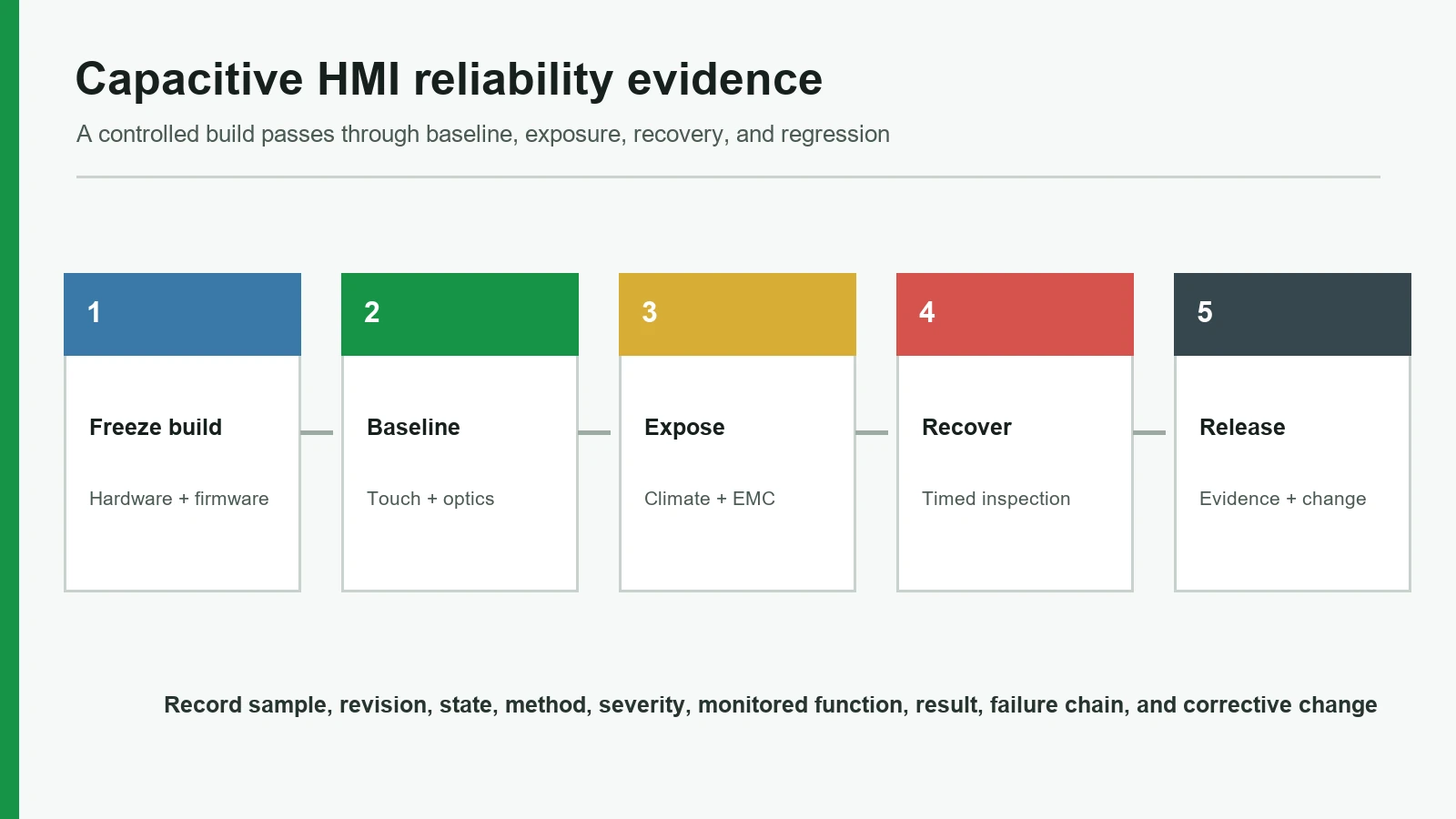
A useful test matrix starts with failure modes and use conditions, then assigns methods. Starting with a chamber list often produces activity without coverage: samples spend hours at temperature, but nobody monitors false touches; an ESD report says “pass,” but the controller reset and recovered without the host logging it; the bonded panel looks clear at room temperature, but edge lift appears only after mounting.
IEC 62908-13-10:2016 is a direct reference for environmental durability testing of capacitive and resistive touch display modules, touch sensor modules, and test pattern cells. It can anchor the touch-module portion of a plan. IEC 61000-4-2:2025 addresses ESD immunity for electrical and electronic equipment. Other IEC 61000-4 methods address different phenomena, such as radiated RF, EFT/burst, and conducted RF. These references identify repeatable methods—not the severity, sample size, or acceptance criterion for an unnamed product.
Validation matrix template
| Validation block | Define before test | Observe during exposure | Post-test acceptance family | Method / evidence anchor | Primary ownership |
|---|---|---|---|---|---|
| Baseline optics and cosmetics | Lighting, angle, distance, display patterns, defect map, allowed zones | Usually not applicable; capture if powered | No new defects beyond drawing/quality limits; baseline map updated | Controlled visual/optical work instruction; adhesive supplier data | HMI assembler + OEM quality |
| Dry touch response | Target grid, actuation object, speed, force only if relevant, edge/corner paths, gestures | Coordinates, misses, false touches, latency, resets, communications | Project limits for detection, accuracy, gesture, and host response | Controller diagnostic logs; ISO 9241-210 context | Controller/firmware owner + OEM HMI |
| Glove operation | Glove material, thickness, dry/wet state, fit, operator method, required gestures | Same channels as dry test; note pressure-dependent behavior | Required functions pass with named glove; unintended input rejected | Controller-vendor guidance; project use study | OEM use owner + controller owner |
| Water / cleaning | Liquid chemistry, amount or film state, droplets versus pooling, orientation, dwell, wipe, drainage | False touch, lockout, intended wet touch, tracking, resets, ingress indicators | Defined behavior during exposure and after drain/dry/recovery | Controller guidance; enclosure plan; IEC 60529 only for enclosure claim | OEM + enclosure + controller owners |
| Electrical noise / EMC | Supply, charger/VFD/motor states, cables, ground, shield, display image, ports, IEC phenomenon | Touch/host event log, coordinates, false/missed events, resets, data errors | Performance criterion for each phenomenon and operating mode | IEC 61000-4-2 and applicable IEC 61000-4-x/product standard | OEM EMC + electronics + firmware |
| Cold, heat, and transitions | Operating/storage states, ramp, dwell, low/high limits, cycles, condensation policy | Touch response, display state, current, logs when powered | Functional, bond, optical, seal, connector, and cosmetic criteria | IEC 62908-13-10; applicable IEC 60068 method selected by plan | OEM validation + assembler |
| Humidity / condensation | Temperature-RH profile, bias/power, orientation, venting, recovery | Leakage symptoms, touch drift, false events, display/communication behavior | No prohibited corrosion, bond change, optical defect, or functional loss | IEC 62908-13-10; applicable damp-heat method | OEM validation + material/process owners |
| Mechanical fit / clamp | Housing flatness, datum scheme, bezel clearance, gasket compression, torque, support | Touch map and display appearance while assembled | No binding, edge error, light leakage, mura, crack, connector strain, seal discontinuity | Assembly drawing, tolerance analysis, fixture correlation | Mechanical owner + assembler |
| Vibration / shock / impact | Installed orientation, fixture, cable restraint, powered state, axes, pulse/spectrum, impact location | Intermittent contacts, false events, resets if powered | Functional check plus connector, bond, glass, frame, fastener, cosmetic inspection | Applicable product standard / IEC 60068 method chosen by OEM | OEM validation + mechanical/electrical owners |
| Chemical and cleaning durability | Exact agents, concentrations, wipe material, dose, frequency, dwell, rinse, temperature | Surface tack, staining, coating change, unintended touches if powered | Drawing-specific visual, legibility, surface, bond, and functional limits | Material supplier data + OEM cleaning protocol | OEM use/quality + material owner |
| Final regression and evidence | Production-intent revisions, full screen map, all operating modes | Automated and manual event logs | All criteria met; deviations closed; samples dispositioned | Approved validation procedure and report | OEM design authority |
The matrix is intentionally conditional. A marine helm, packaging controller, laboratory analyzer, vehicle interior, and outdoor kiosk do not share one correct water state, temperature profile, EMC setup, glove, cleaning agent, or acceptance criterion. The plan should explain why each row represents the intended use—or why it is not applicable.
Precondition, expose, recover, inspect
Each matrix row needs a sequence, not just a test name:
Baseline → precondition → mount/configure → expose while monitoring
defined recovery → functional regression → physical inspection
correlate data → disposition sample and requirement
Order can matter. Humidity before mechanical stress may reveal a different weakness than vibration followed by humidity. Chemical wipes can change a coating before glove or water testing. Thermal cycling can move a bond line or gasket before EMC evaluation. Do not combine stresses merely to make a test “harder.” Combine or sequence them only where the field history, physics, applicable standard, or risk analysis gives a reason, and keep diagnostic samples when interaction effects would otherwise hide the root cause.
Acceptance-criterion anatomy
| Required field | Question to close before approval |
|---|---|
| State | Which hardware, firmware, screen, power, ground, mount, glove, and liquid configuration applies? |
| Stimulus | Which target, gesture, IEC phenomenon, climate profile, force, cleaner, or mechanical input is applied? |
| Observed output | Which raw signal, coordinate, host event, visual state, current, reset, or defect is recorded? |
| Allowed response | Which numerical project limit or explicitly described behavior is acceptable? |
| Prohibited response | Which false activation, miss, lockout, damage, ingress, or cosmetic change causes failure? |
| Recovery | May function degrade temporarily; if so, under which performance criterion and recovery condition? |
| Evidence | Which log, map, photograph, profile, inspection record, or raw file proves the result? |
“Works normally” is not an acceptance criterion. A defensible criterion names the state, stimulus, measured output, allowed deviation, prohibited behavior, recovery, and evidence. Examples of criterion form—not universal limits—include:
- During radiated RF exposure in the specified operating mode, the event log records no unintended activation of a safety-relevant control; permitted coordinate deviation and temporary degradation follow the project performance criterion.
- With the named wet glove and liquid film, the interface accepts the required single-touch controls but may intentionally suppress multi-touch gestures; dry-operation behavior returns within the project-defined recovery condition.
- After the selected humidity exposure and recovery, no new bubble, edge lift, print change, corrosion indication, or display mura exceeds the approved drawing and cosmetic standard.
- In the production housing at minimum and maximum tolerance conditions, the active area remains clear of bezel interference and the FPC retains the required bend and connector engagement.
Numbers belong in the approved requirement, but they must come from the product and use case. Inventing a generic accuracy, latency, bubble diameter, temperature band, dwell, or ESD level would make this guide look precise while weakening the actual validation.
4. Evaluate Nine Parts of the Plan
4.1 Define the environment and the failure first
Start with what the equipment will encounter and what the user must accomplish. Name operating and storage temperature, humidity and condensation, altitude if relevant, sunlight, contaminants, cleaning chemicals, liquid state, gloves, operator posture, display content, mounting, power source, nearby emitters, cables, and maintenance. Then define failures: missed critical control, unintended activation, coordinate drift, lockout, reset, delayed recovery, optical defect, loss of bond, cracked lens, seal path, connector intermittency, or illegible decoration.
The requirement links each exposure to an intended and prohibited behavior, a configuration, and an owner.
“Industrial grade,” “harsh environment,” or “water resistant” is treated as a test specification.
4.2 Control every revision that can move the signal
The validation BOM should identify more than commercial part numbers. Record drawings, artwork, sensor pattern, FPC, controller PCB, grounding hardware, adhesive and process, display, gasket, enclosure, firmware, tuning checksum, and host build. Retain sample serial numbers and material lots where traceability is needed.
Microchip AN2934 explains the directional effect of dielectric distance on capacitive coupling. Microchip AN3908 and Infineon’s PCAP guidance add electrode, shielding, edge, routing, display, and SNR considerations. These relationships explain why a lens-thickness change or new display cannot be closed as a cosmetic substitution.
The report can reconstruct exactly which physical and software configuration each sample used.
A passing prototype contains hand tuning, a different display, an unrecorded ground strap, or an adhesive substitution absent from the production release.
4.3 Validate the optical bond as part of the sensor stack
Optical bonding affects more than appearance. Cover and sensor flatness, decoration steps, adhesive thickness and rheology, trapped contamination, lamination or dispense parameters, cure/conditioning, rework, and edge design can alter stress and dielectric uniformity. Establish a baseline defect map under controlled illumination and display patterns, then repeat it after climate and mechanical tests.
The 3M CEF28XX/OCA 802XX data sheet lists nominal adhesive examples of 100, 150, 200, 250, and 350 µm. That supplier-specific range is useful because it exposes an incomplete drawing callout: “OCA” alone does not specify grade, thickness, tolerances, surface preparation, step coverage, or process. It is not evidence that JASPER uses this family.
The approved stack drawing, material grade, process revision, conditioning, inspection setup, and post-stress criteria travel with the sample record.
A room-temperature bubble check is the only bond validation, or a supplier data sheet replaces testing of the actual decorated stack.
4.4 Map touch response across state, location, and action
Touch response is a matrix, not one sensitivity value. Test center, edges, corners, keys near decoration boundaries, gestures, approach paths, repeated activation, and transitions between screens. Include dry finger, every required glove, and wet states. Log raw or diagnostic channels when the controller permits it, along with host events and visible feedback.
Texas Instruments and Infineon both treat cover stack, electrode design, grounding, shielding, display noise, and tuning as coupled variables. A panel that detects a finger on a quiet evaluation board may behave differently over the final display with production cables and power.
The test identifies target locations, actuation objects, gestures, screen states, required detections, prohibited detections, recovery, and data channels.
An operator taps a few icons, sees them open, and signs “touch passed.”
4.5 Separate glove, water, and ingress questions
Glove operation asks whether a named dielectric input can produce the intended signal. Water behavior asks whether droplets, films, pooling, flow, residue, or a wet glove create intended or unintended input. Ingress protection asks whether the tested enclosure resists entry under an IEC 60529 classification. These are related but not interchangeable.
Define whether the HMI should reject all input during heavy water, accept large single controls, track a wet finger, disable gestures, or enter a lockout mode. Define what happens after wiping, draining, or drying. The detailed water and glove tuning guide can hold controller-level tuning strategy; this validation plan owns the equipment behavior and evidence boundary.
Liquid, glove, orientation, amount/state, touch expectation, grounding, enclosure, drainage, recovery, and failure log are all specified.
“Works with gloves and water” appears without naming either glove or water condition, or an IP code is assigned to a loose panel.
4.6 Monitor function during electrical noise tests
Capacitive sensing measures small changes against a noisy electrical system. Power conversion, motors, drives, chargers, displays, cable coupling, poor reference connections, and transient events can change the margin. TI’s TIDM-CAPTOUCHEMCREF shows this as a system-level design problem involving the controller and power architecture—not a label that can be added after sensor qualification.
IEC 61000-4-2 covers ESD. Radiated RF, EFT/burst, and conducted RF require other IEC 61000-4 methods where applicable. During each exposure, monitor touch and host events in the operating modes that matter. A post-test tap check can miss a false activation, brief lockout, coordinate jump, reset, or communication fault.
The plan identifies phenomenon, ports, cables, grounding, display state, supply, operating mode, monitoring, performance criterion, recovery, and applicable product-standard basis.
One ESD test is presented as “EMC certified,” or the screen is unpowered during every test despite powered field exposure.
4.7 Make temperature and humidity represent transitions
A touch panel environmental test must address the transitions that create failure, not only chamber endpoints. Cold start, hot operation, powered heating, rapid movement into humid air, condensation, storage-to-operation recovery, and differential expansion across glass, adhesive, sensor, display, frame, and housing can produce different outcomes.
IEC 62908-13-10:2016 provides environmental durability methods for touch modules. An applicable IEC 60068 method or product standard may also govern an OEM plan. The project must still define profile, specimen state, ramp, dwell, cycles, recovery, interim monitoring, and acceptance. Avoid condensation unless intended and controlled; if condensation is a field condition, test and contain it deliberately rather than allowing an accidental chamber artifact.
Functional monitoring and post-exposure bond, optical, connector, seal, and cosmetic checks share a controlled baseline.
The report lists chamber limits but not sample temperature, power state, recovery, functional state, or observed transitions.
4.8 Test the assembly in its mechanical constraint
Glass, sensor, display, adhesive, gasket, and frame respond to housing flatness, bezel clearance, clamp distribution, screw torque, support points, connector load, and FPC routing. An HMI can pass flat on a bench and develop edge errors, mura, light leakage, glass stress, or bond strain when clamped into a tolerance-limit housing.
Use drawing datums and inspect minimum/maximum tolerance conditions. Correlate the test fixture to production mechanics. Where vibration, shock, or impact applies, define installed orientation, fixture stiffness, cable restraint, axes, powered state, pulse or spectrum, and inspection. The applicable equipment standard or OEM requirement—not a generic blog value—sets severity.
The test includes production-intent housing, gasket, fasteners, torque, cable routing, ground contacts, and tolerance extremes.
A rigid fixture holds the active stack differently from the product, or mounting hardware is absent from environmental and touch tests.
4.9 Require evidence that survives a design change
A release package needs the procedure and raw record, not only a certificate. Retain sample IDs, configuration, calibration status, setup photographs, fixture drawings, environmental profiles, event logs, touch maps, optical/cosmetic baselines, deviations, failure analysis, retest scope, and approvals. State whether a failure was reproduced and whether corrective action changed hardware, process, firmware, or the requirement.
The same evidence supports change assessment. A new display, adhesive, frame coating, FPC route, controller firmware, tuning file, or enclosure may require full retest, partial regression, or documented no-impact analysis. That decision should use the original failure mechanisms and margins.
Every “pass” traces to a revision, criterion, raw result, deviation status, and design authority.
A one-page summary cannot show what was tested, what changed, or whether transient failures were monitored.
5. Run HMI Assembly Validation in Six Steps
Six-step execution map
| Step | Controlled output | Release stop |
|---|---|---|
| 1 | Context-of-use requirements and failure definitions | No test request while “industrial grade” substitutes for conditions |
| 2 | Requirement-to-failure-to-test trace | No orphan requirement or unexplained test |
| 3 | Traceable production-intent and tolerance-limit samples | No formal result from an unidentified prototype stack |
| 4 | Baseline data, preconditioning, fixtures, and instrumentation | No exposure before the starting state is recorded |
| 5 | Timestamped stress and live functional evidence | No post-test-only verdict where transient failure matters |
| 6 | Root cause, correction, regression, deviation closure, and approval | No release from an unexplained anomaly |
Step 1 — Convert use conditions into requirements
Bring mechanical, electrical, firmware, display, quality, regulatory, service, and end-user representatives into one requirements review. List normal use, reasonably foreseeable misuse, cleaning, gloves, liquids, electromagnetic sources, climate transitions, installation, storage, transport, and maintenance. Rank failure consequences. The output is a requirement set with observable pass/fail language—not a copied list of laboratory methods.
Step 2 — Create a failure-mode-to-test map
For each requirement, identify a credible physical or software path to failure and the evidence that would detect it. Use the complete stack diagram. If no test detects a failure, add analysis, inspection, monitoring, or a test. If a test has no linked requirement or risk, justify it or remove it.
Step 3 — Build traceable production-intent samples
Freeze the configuration record and sample plan. Include tolerance-limit or intentionally varied specimens where edge conditions matter; random nominal samples alone may never challenge bezel clearance, gasket compression, bond steps, or weak signal locations. Use prototyping to retire architecture and integration questions before formal verification, while keeping prototype evidence separate from production release.
Step 4 — Baseline and precondition
Record touch maps, diagnostic channels, host events, current where relevant, display patterns, cosmetic defect maps, bond condition, connector state, dimensions, and enclosure assembly. Apply defined stabilization or adhesive conditioning. Photograph the setup and identify instruments, fixtures, software, and calibration status.
Step 5 — Execute exposures with live monitoring
Run the approved sequence. Monitor the functions that could fail during—not just after—the stress. Preserve timestamps so chamber, EMC, touch, host, power, and video records can be correlated. Use diagnostic control samples where combined stresses would make a failure hard to isolate. Follow the quality and testing evidence route for project-specific method discussions; the route itself is not proof of a particular JASPER capability.
Step 6 — Correlate, correct, regress, and release
Treat every anomaly as data until dispositioned. Reproduce it, isolate the layer, correct the responsible requirement/design/process/configuration, and choose regression scope from the failure mechanism. Release only when deviations are closed or formally accepted by the design authority. Archive the test package with the configuration so later changes can be judged against evidence instead of memory.
6. Diagnose the Failure Chain, Not the Symptom
A false touch or bubble is an observation, not a root cause. Start with the first uncontrolled change in the chain:
Incomplete use requirement
wrong stack, tolerance, process, or controller assumption
stress changes dielectric, bond, ground, fit, moisture, or noise
sensor signal or mechanical/optical state moves
controller or host makes the wrong decision
user sees a miss, false action, lockout, reset, defect, or unsafe state
Use synchronized evidence to locate that change. A false touch during EFT/burst could correlate with a supply transient, ground shift, FPC pickup, controller threshold event, communication error, or host debounce fault. Edge misses after thermal cycling could correlate with bond change, housing distortion, bezel interference, electrode margin, or configuration drift. The repair differs for each cause.
A practical triage sequence is: reproduce the symptom; compare the sample with its baseline and control; inspect physical and connector state; review power/ground/noise logs; inspect controller diagnostic data and tuning checksum; compare host events; then vary one suspected factor. Do not retune the controller first and call the problem solved. Tuning may mask a mechanical, process, or EMC weakness and reduce margin elsewhere.
7. When Projected Capacitive or Full Optical Bonding Is Not Best
Architecture decision boundary
| Field requirement | PCAP / full bond may fit when… | Reconsider when… | Candidate alternative |
|---|---|---|---|
| Thick or nonconductive input | A named glove can be tuned and verified with adequate margin | Passive stylus or thick glove input is mandatory across all states | Resistive touch or physical control |
| Heavy or continuous water | Intended wet behavior and lockout/recovery can be defined | Flow or pooling makes touch intent intrinsically ambiguous | Physical keys, guarded controls, hybrid HMI |
| Tactile confirmation | Visual/audio feedback is acceptable | Eyes-free confirmation or detent is safety- or task-critical | Membrane switch, silicone keypad, electromechanical key |
| Display service | Bonded module replacement is acceptable | Field display replacement and modular service dominate | Air gap or perimeter bond |
| Low-volume process | Bond process and inspection are controlled | Process variation cannot be characterized economically | Air gap, perimeter bond, or separate overlay |
| Mechanical stress | Actual bonded stack can be validated in its housing | Differential expansion or housing distortion lacks margin | Decoupled stack or revised mounting |
Projected capacitive touch is not the default for every industrial HMI. A capacitive-versus-resistive guide should be revisited when the required input includes thick nonconductive gloves, a passive stylus, continuous heavy water, very simple fixed controls, or a use case where tactile confirmation matters more than gesture and optical performance. Resistive touch, physical keys, a membrane switch, or a hybrid interface may produce a clearer validation boundary.
Full optical bonding is also not automatically best. An air gap or perimeter bond may be preferable when display replacement, repair, low-volume process maturity, thermal-stress decoupling, supplier interchangeability, or cost dominates. Full bonding can support a thin integrated stack and control internal interfaces, but it adds material/process dependencies and can transmit stress between the cover, sensor, and display. Select it only when the project can validate the actual stack and production process.
The decision is not “which technology is toughest?” It is which architecture produces the required user behavior with controllable failure modes, evidence, and service strategy.
8. Project Input and Sample Approval Checklist
The fastest route to a useful validation plan is to define the HMI validation environment before requesting tests. Send the following package to the touch-panel, display, bonding, controller, enclosure, and test owners.
Project input checklist
| Input | Required detail | Release question it answers |
|---|---|---|
| Context of use | Equipment, user, location, duty cycle, critical controls, misuse, service | What must work, and what failure is unacceptable? |
| Climate | Operating/storage ranges, transitions, RH, condensation, altitude, sunlight | Which environmental profiles represent field exposure? |
| Liquids and cleaning | Chemistry, concentration, dose, film/pooling, orientation, wipe, dwell, frequency | What should touch and enclosure do during and after liquid exposure? |
| Gloves and input tools | Material, thickness/specification, dry/wet/contaminated state, gestures | Which input objects must be detected or rejected? |
| EMC environment | Supply, drives/motors, radios, cables, ports, grounding, applicable product standard | Which IEC 61000-4 phenomena, setups, and modes belong in the plan? |
| Mechanical package | 2D/3D datums, bezel, housing flatness, gasket, torque, supports, FPC and connector routing | Does the test reproduce production constraint and tolerance limits? |
| Optical/cosmetic standard | Lighting, angle, display patterns, zones, defect definitions and limits | How will bond, print, glass, and display changes be judged repeatably? |
| Electronics/software | Display, controller, PCB, power, cables, ground/shield, firmware, tuning, host builds | Can each result be tied to a reproducible electrical configuration? |
| Standards and risk | Product/vertical standards, hazard analysis, performance criteria, regulatory owner | Who selects severities and approves residual risk? |
| Change plan | Alternate materials, second sources, expected firmware/display/enclosure changes | Which results need regression after a change? |
Sample approval closeout
Before a first article or validation lot is accepted, verify that:
- [ ] each sample has a unique ID and complete hardware, material, process, firmware, tuning, and host revision record;
- [ ] the assembly drawing defines cover, bond, sensor, display, frame, gasket, bezel, fasteners, connector, FPC, ground, and shield interfaces;
- [ ] baseline touch maps, event logs, display patterns, optical/cosmetic maps, and setup photographs exist;
- [ ] every exposure links to a requirement, failure mode, method, severity rationale, operating state, monitored function, criterion, and owner;
- [ ] gloves, liquids, cleaners, cables, power supplies, fixtures, and enclosure builds match named specifications;
- [ ] failures and deviations show root cause, correction, affected samples, retest scope, and approval;
- [ ] post-test inspection uses the same conditions as baseline;
- [ ] component results are not represented as enclosure IP, finished-equipment EMC, safety, or regulatory approval;
- [ ] open design or evidence gaps remain visible rather than being converted into a conditional “pass”; and
- [ ] the design authority signs the final report and sample disposition.
A related capacitive touch control panel application can help publishing teams connect this framework to a concrete interface architecture. Its project-specific evidence must remain separate from the generic validation guide.
9. Frequently Asked Questions
What is capacitive HMI reliability testing?
Capacitive HMI reliability testing verifies that a defined cover, bond, sensor, display, mechanics, electronics, controller configuration, and host interface deliver required touch behavior through specified environmental, electrical, mechanical, and use conditions. It also checks physical, optical, and cosmetic integrity. Testing only a loose sensor answers a narrower component question.
Which standards belong in capacitive HMI reliability testing?
IEC 62908-13-10:2016 is directly relevant to environmental durability methods for touch modules. IEC 61000-4-2:2025 covers ESD immunity, while other IEC 61000-4 methods cover separate EMC phenomena. IEC 60529 applies to enclosure ingress protection. The equipment’s product standard and risk analysis must select methods, severities, operating modes, and acceptance criteria.
How should an OEM test a capacitive touchscreen with gloves?
Name the glove material and specification, dry/wet/contaminated state, required targets and gestures, screen state, mounting, grounding, controller configuration, and expected recovery. Test edges and corners as well as central targets. Record missed and unintended events at both controller and host level. A generic “glove mode” claim is not a validation requirement.
Does an IP65 or IP67 enclosure rating prove reliable wet touch?
No. IEC 60529 classifies enclosure protection against ingress under defined tests; it does not prove that a capacitive controller will accept or reject touches correctly with droplets, films, pooling, flow, residue, or a wet glove. Ingress and wet-touch behavior need separate requirements and may be evaluated together at finished-enclosure level.
Should touch function be monitored during EMC and environmental tests?
Yes, when the field use is powered and the relevant failure can occur during exposure. Live monitoring can capture false touches, misses, coordinate shifts, resets, communication errors, lockouts, and recovery that a post-test tap check would miss. The test plan should define logged channels, timestamp correlation, operating modes, and performance criteria.
How many samples are needed for HMI assembly validation?
There is no universal sample count. It depends on the applicable standard, failure consequences, design maturity, variability, destructive inspections, tolerance coverage, and statistical objective. The plan should include traceable production-intent samples and deliberate worst-case constructions where geometry, bond steps, display noise, grounding, or housing tolerance can control the result.
Can a controller be retuned after the HMI stack changes?
It can, but retuning is a design change and requires regression. A new cover, adhesive, sensor, display, frame, ground, FPC, power supply, or enclosure may change signal and noise margin. Record the tuning checksum, explain why it changed, confirm that the correction does not hide a physical defect, and rerun affected dry, glove, water, EMC, and environmental conditions.
What belongs in an HMI assembly validation report?
Include requirements, risk links, sample IDs, complete configuration, procedures, fixtures, instruments and calibration status, setup photographs, environmental profiles, event logs, touch maps, baseline and post-test cosmetic evidence, deviations, failure analysis, corrective actions, regression rationale, raw data, sample disposition, and design-authority approval. A pass summary without this context is not reusable evidence.
10. Define the HMI Validation Environment Next
Before asking any manufacturer or laboratory for a test plan, define the HMI validation environment: users, gloves, liquids, cleaners, climate, mechanical package, power and EMC sources, critical controls, failure consequences, applicable standards, and required evidence. Then freeze the bonded stack and controller/host configuration. That sequence turns a list of tests into a release decision.
Technical References
- Source: IEC 62908-13-10:2016 Touch Display Reliability. Accessed 2026.
- Source: IEC 61000-4-2:2025 ESD Immunity. Accessed 2026.
- Source: IEC 60068-2-14:2023 Temperature Change. Accessed 2026.
- Source: IEC 60068-2-78:2025 Damp Heat. Accessed 2026.
- Source: Texas Instruments CapTIvate guidance. Accessed 2026.
- Source: 3M CEF28XX/OCA 802XX technical data sheet. Accessed 2026.
- Source: Beijer Electronics publishes this range. Accessed 2026.
- Source: Pro-face product specification. Accessed 2026.
- Source: IEC 62908-13-10:2016 — Reliability test methods of touch displays: Environmental durability test methods. Accessed 2026.
- Source: IEC 61000-4-2:2025 — Electrostatic discharge immunity test. Accessed 2026.
- Source: IEC 60529 — Degrees of protection provided by enclosures. Accessed 2026.
- Source: ISO 9241-210:2019 — Human-centred design for interactive systems. Accessed 2026.
- Source: CapTIvate Technology Guide — Design Guide. Accessed 2026.
- Source: TIDM-CAPTOUCHEMCREF Noise-Tolerant Capacitive Touch HMI Reference Design. Accessed 2026.
- Source: Industrial Capacitive Touchscreen Design Made Simpler. Accessed 2026.
- Source: AN2934 Capacitive Touch Sensor Design Guide. Accessed 2026.
- Source: AN3908 / QTAN0080 maXTouch Sensor Design Guide. Accessed 2026.
- Source: CEF28XX/OCA 802XX Series Technical Data Sheet. Accessed 2026.
Review the complete HMI assembly before design release
Send the front-panel drawing, stack, display, circuit, connector, enclosure, service conditions, and acceptance plan for review.