
Reliable wet and gloved touch comes from controlled signal margin across the complete lens, sensor, display, ground, enclosure, firmware, and host state. Tuning starts only after those conditions are defined.
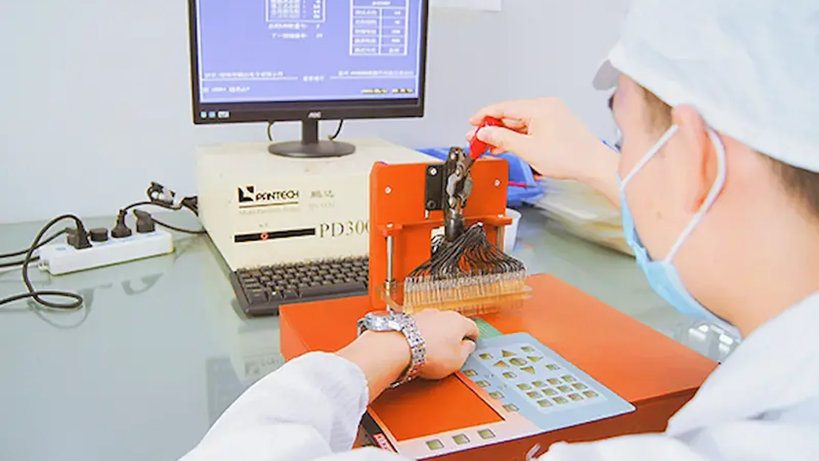
A PCAP touch panel should be reviewed as a sensing system, not a loose sensor. The cover lens, printed border, adhesive, air gaps, electrodes, display, chassis, controller, firmware, bezel, gasket, and drainage path can all change the result. JASPER is one manufacturer an OEM can ask to review the physical stack; controller configuration, equipment behavior, and final validation still need explicit ownership in the project specification.
1. Decide the Required Wet and Gloved Behavior Before Tuning
A useful requirement states what the interface must accept, what it must reject, and how it must recover. “Glove compatible” omits the glove model, material, layers, fit, condition, contact geometry, target, and operator posture. “Waterproof touch” is also ambiguous: it may refer to enclosure ingress protection, wet-finger use, droplet rejection, temporary lockout during a spill, or survival during washdown.
Those are different engineering problems. Wet finger touch sensing asks the controller to recognize an intended contact while liquid changes the electrical coupling. Water rejection capacitive touch asks the system to ignore or classify liquid when no valid user input exists. A cleaning lockout deliberately rejects input. IEC 60529 addresses protection provided by enclosures under specified tests; it does not establish that an interface remains usable while its surface is wet (IEC 60529).
The first project artifact should therefore be a behavior table, not a tuning file.
| Surface and input state | Required response to specify | Invalid event to prevent | Evidence to retain |
|---|---|---|---|
| Dry surface, bare finger | Accept approved targets and gestures | Miss, adjacent target, edge error | Coordinates/events, response and release record |
| Dry surface, specified glove | Accept or reject by glove article | Sleeve, palm, hover, neighboring target | Exact glove ID, target result, rejected-event log |
| Wet finger on dry surface | Accept, restrict, or reject | Drag, false second point, stuck release | Liquid method, movement, coordinates, recovery |
| Droplets with no user | Ignore or enter a defined wet state | Ghost touch, wake, repeated command | Droplet placement, dwell, unattended event log |
| Continuous film with no user | Continue, restrict, or lock out | Random coordinates or state oscillation | Coverage, orientation, state and recovery trace |
| Film plus specified glove | Project-defined response | False acceptance, wrong target, non-recovery | Combined-condition test record |
| Moving runoff | Ignore or restrict controls | Swipe, edge touch, unwanted wake | Flow path, orientation, event trace |
| Cleaning wipe | Enter cleaning mode or reject | Drag, multi-touch, machine command | Real wipe procedure, lockout and exit record |
| Drying or residue | Recover by a defined rule | Premature enablement, permanent lockout | Recovery time/state, residue condition, baseline trace |
An industrial-control panel adds machine consequences to this table. A false coordinate need not become a command: the touch controller, host application, safety architecture, and operator feedback can provide separate decision layers. The industrial-control application page is the relevant internal route for that installed-use context. It may be unpublished during the site build; the final URL is retained intentionally.
2. Eight Criteria for Capacitive Touch Water Glove Tuning
A defensible design review covers eight linked criteria: state definition, dielectric stack, electrode geometry, signal margin, ground/shield/guard/drainage, controller behavior, installed validation, and change control. Treating one criterion in isolation usually moves the failure rather than removing it.
2.1 Define the glove, liquid, target, and decision boundary
The glove is a controlled test article. Record its manufacturer, model, material, size, number of layers, fit, fingertip construction, surface condition, moisture condition, and intended posture. A tight nitrile examination glove and a loose coated work glove do not present the same dielectric spacing or contact footprint. A glove touch panel requirement should also identify the smallest target, edge targets, taps, dwell, drag, repeated inputs, and any gesture or multi-touch behavior.
The liquid needs comparable control. Distilled water, tap water, saline contamination, cleaner residue, condensation, isolated drops, a continuous film, runoff, and pooling can produce different coupling paths. Microchip’s AVR3002 Moisture Tolerant QTouch Design explains that moisture can cause positive or negative signal shifts and that baseline behavior, pooling, guard sensing, and recovery matter (Microchip AVR3002).
The requirement names each glove article and liquid state, the intended target response, prohibited event, lockout behavior, feedback, and recovery condition.
The supplier is asked to prove “any glove,” “wet use,” or “waterproof operation” without a controlled article or pass/fail rule.
| Use-state input | Record before tuning | Acceptance decision |
|---|---|---|
| Glove | Manufacturer, model, material, size, layers, fit, fingertip and dry/wet condition | Required targets respond; prohibited targets and gestures remain rejected |
| Liquid | Chemistry, amount, distribution, temperature, dwell, orientation and drainage | Intended behavior is defined during exposure, after drainage and after recovery |
| Touch action | Target size and location, tap/hold/drag/gesture, speed and repetition | Controller and host produce the required event without unintended events |
| Recovery | Drain, wipe, dry, recalibrate, timeout or power-cycle sequence | Normal operation returns within the approved time and state boundary |
2.2 Freeze the complete dielectric and mechanical stack
The user does not touch the electrode directly. The electric field crosses every dielectric layer between the finger and sensor, while nearby conductors shape the field from the rear and edges.
bare or gloved finger
surface coating / texture
cover lens or graphic front
printed ink and opaque border
adhesive or optical bonding layer
local voids, bubbles, steps, or air gaps
sensor substrate and electrode pattern
rear adhesive / display gap / optical stack
display, PCB, chassis, shield, ground
controller measurement and host decision
Microchip AN2934 treats cover properties, sensor design, traces, shielding, and grounding as related inputs rather than separate checkboxes (Microchip AN2934). Infineon AN85951 likewise ties overlay and electrode decisions to capacitance, signal-to-noise ratio, shield/guard design, and tuning (Infineon AN85951).
A flat coupon attached with temporary tape is useful for early comparison, but it cannot approve a bonded, curved, printed, gasketed production assembly. Air gaps can vary locally. An opaque printed border can differ from the clear viewing area. A metal bezel, display frame, fastener, or gasket compression change can alter edge behavior.
The tuning build uses production-intent cover material, coating, print, adhesive coverage, sensor registration, display location, bezel, gasket compression, ground, and enclosure support.
Cover thickness is the only mechanical input on the tuning request, or a bare sensor result is presented as evidence for the finished stack.
2.3 Match electrode size and pitch to the real input
Electrode geometry should follow the approved finger or glove contact, visual target, neighboring targets, cover stack, edge condition, and controller method. Larger is not automatically safer. Increasing electrode area may improve a weak valid signal, but it can also increase parasitic coupling, response to liquid, interaction with adjacent channels, and sensitivity to rear-side conductors. A small electrode may preserve spacing yet leave too little valid-touch margin through the cover and glove.
Texas Instruments describes electrode geometry, overlay, nearby ground, parasitic capacitance, and signal-to-noise ratio as linked design factors in the CapTIvate Technology Guide (TI CapTIvate Design Guide). The same guide distinguishes self-capacitance and mutual-capacitance considerations; a button guard strategy cannot simply be copied to every coordinate matrix.
Review center targets, border targets, corners, sliders, wheels, inactive areas, and traces. Include water bridges between a target and its neighbor, between an electrode and a guard, and across a printed border. On a coordinate panel, define large-object rejection, edge tracking, palm and sleeve behavior, wet-finger drag, gesture enablement, and multi-touch expectations.
The design record links target dimensions, electrode pattern, pitch, cover stack, exact glove contact, edge geometry, and measured channel or coordinate behavior.
A geometry change is accepted because one center key responds, without checking adjacent targets, edges, water bridges, and installed display coupling.
2.4 Budget signal margin instead of “turning up sensitivity”
A controller must separate the smallest approved touch from the largest invalid change caused by noise, water, baseline drift, assembly variation, display operation, power states, and unintended objects. A useful review model is conceptual:
usable decision margin
= smallest valid touch response
− largest combined invalid response and variation
This is not a controller equation. It is a decision boundary. TI uses signal, noise, and SNR concepts throughout the CapTIvate design guidance, while Infineon AN85951 addresses signal-to-noise design and parasitic capacitance. Neither source supports one universal threshold for every panel.
Log raw measurements where the controller permits: reference or baseline, touch delta, noise, threshold, hysteresis, detected state, rejected state, guard/wet state, coordinates, response, release, and recovery. Tag every file with hardware, firmware, controller configuration, cover, sensor, display, enclosure, glove, liquid, orientation, and power condition. A screenshot of a single clean trace is not a margin study.
Sensitivity changes often expose a tradeoff. A lower threshold may detect a gloved touch and also admit water, sleeve contact, display noise, or production variation. A higher threshold may reject an invalid liquid event and miss the smallest approved glove contact. Geometry, stack, ground, shielding, drainage, and state logic may need correction before another threshold change.
Evidence compares the weakest valid state with the strongest invalid state across production-intent assemblies and installed electrical conditions.
One threshold from one bench sample is described as the water-and-glove solution.
2.5 Give ground, shield, guard, bezel, and drainage separate jobs
These features solve different problems. Ground provides an electrical reference and return path, but a conductor close to an electrode can add parasitic capacitance and reduce useful sensitivity. A rear shield may limit coupling from a display, battery, cable, motor, or chassis. Depending on the controller, it may be grounded, driven, patterned, or omitted. A guard channel can monitor a perimeter or liquid condition in selected architectures. Drainage and enclosure geometry control where liquid sits and which conductors it bridges.
TI’s TIDM-1021 shows liquid-tolerant touch as coordinated hardware and software, including false-touch rejection behavior (TI TIDM-1021). The CapTIvate guide describes guard-channel spill rejection as one design approach. These sources do not establish that a guard ring makes a panel waterproof.
Review bezel height, surface slope, recesses, gasket paths, seams, fasteners, tail exits, connector location, and low points. A design that ignores moving runoff may still fail under pooling. A design that rejects a large spill may still misclassify one droplet at an edge electrode. The enclosure decides the liquid pattern; the controller only measures the resulting electrical state.
The drawing and test plan assign a stated purpose to ground, rear shield, driven shield if used, guard channel, bezel, gasket, and drainage path.
“Add a guard ring” is the only water-rejection action, or an untested component is assigned an IEC 60529 IP rating.
2.6 Specify controller modes, transitions, and recovery
Controller configuration may expose baseline update, gain, touch and release thresholds, hysteresis, debounce, filters, scan frequencies, noise handling, channel grouping, large-object rejection, recalibration, wake behavior, guard logic, or dedicated glove/wet functions. Names and availability differ among Texas Instruments, Microchip, Infineon, and other controller families. A generic “glove mode” requirement is therefore not portable.
State transitions deserve the same attention as steady operation:
STARTUP
DRY_NORMAL
GLOVE_ENABLED
WET_DETECTED
CLEANING_LOCKOUT
RECOVERY
FAULT
Those labels are examples, not a required implementation. Define entry evidence, enabled controls, host permissions, visible or audible feedback, exit conditions, timeout, power-cycle behavior, diagnostics, and the safe response when classification is uncertain. A controller may report a contact while the host rejects the command. The host may also remain enabled while the touch controller is recalibrating. Test the entire command chain.
| Transition to test | Trigger to control | Evidence to retain |
|---|---|---|
| Dry normal to glove enabled | Approved user action, detected signal state or host command | Configuration revision, entry time, enabled functions and feedback |
| Dry or glove state to wet detected | Named liquid pattern and signal condition | Raw channels, classifier state, host events and prohibited-event log |
| Wet detected to cleaning lockout | Cleaning command or defined liquid coverage | Disabled controls, operator feedback and fault handling |
| Cleaning lockout to recovery | Drain/wipe condition, timeout and recalibration rule | Recovery time, baseline trace and full target regression |
| Any state to fault | Open channel, stuck input, noise or classification uncertainty | Diagnostic code, safe host response, reset rule and retained log |
Baseline tracking presents a specific conflict described in Microchip AVR3002. A response that tracks too quickly can absorb a slow or weak valid event. A response that tracks too slowly can remain displaced after liquid, temperature change, or a cleaning event. Filtering can suppress a transient, yet excessive filtering may delay detection, release, gesture behavior, or recovery.
Hardware and firmware revisions carry an explicit state table, transition tests, host permissions, feedback behavior, recovery evidence, and retained diagnostics.
The tuning package contains undocumented settings, or wet/glove mode can enter and exit without a controlled test or operator indication.
2.7 Validate the production-intent installed system
A staged program isolates causes without confusing early evidence with final approval.
- Sensor/controller coupon: Compare electrode concepts, controller behavior, overlays, gloves, and liquid states. This stage does not approve the display, enclosure, drainage, UI, or equipment.
- Production-intent front stack: Add the actual cover, print, adhesive, sensor, tail, connector, display or representative noise source, shield, ground, and controlled firmware.
- Installed enclosure: Add bezel, gasket, fasteners, chassis, power supply, cables, orientation, drainage, host software, and operator feedback.
- Production/change evidence: Evaluate approved component variation, assembly limits, repeated wet/dry transitions, cleaning, wear, firmware control, replacement, and revalidation triggers.
ISO 9241-210:2019 treats human-centred design as a lifecycle activity for interactive systems (ISO 9241-210:2019). For a wet or gloved HMI, a sensor event alone is not enough. The operator must know whether the touch was detected, the target was accepted, the command was permitted, the machine acted, and the action completed.
Approval evidence comes from production-intent units in the installed electrical and mechanical configuration, with real operators or controlled fixtures and versioned records.
A demonstration video, dry center-touch test, or one hand-built coupon is presented as production qualification.
2.8 Release manufacturing controls and revalidation triggers
Water and glove tuning can change when a part that appears cosmetic changes. A new cover supplier, hard coat, ink stack, adhesive, bond coverage, local air gap, display, bezel finish, cable, connector, ground point, controller lot, firmware revision, or cleaning liquid can move the decision margin.
Release the cover and print drawing; electrode and routing data; sensor-to-cover and sensor-to-display registration; adhesive, gap, and bond process; PCB/FPC and connector revisions; display and power configuration; ground, shield, guard, bezel, gasket, enclosure, and drainage interfaces; controller and firmware version; glove ledger; liquid procedures; fixtures; acceptance rules; approved report; and change owners.
The JASPER testing and quality route can anchor the drawing, sample, assembly, inspection, and change-control discussion. It should not be cited as proof that a specific PCAP water/glove test, controller trace, or installed-equipment result has been completed.
The control plan identifies characteristics, approved revisions, retained evidence, supplier changes, firmware ownership, and events that trigger partial or full revalidation.
A cover, adhesive, display, enclosure, or firmware change can enter production without a touch-performance review.
3. Run the Engineering Handoff in Six Steps
The handoff should move from behavior to evidence. Starting with artwork or an unqualified request for “higher sensitivity” leaves mechanical, electrical, firmware, and quality teams optimizing against different definitions.
Step 1 — Write the use-state specification
List every intended operator and input: bare finger, wet finger, each glove model, layered gloves, invalid sleeve or palm, and any approved stylus. Pair each with dry, droplet, film, runoff, pooling, wipe, residue, and recovery conditions relevant to the equipment. Define target response, forbidden event, command consequence, feedback, and safe fallback.
Step 2 — Issue the production stack, not a nominal lens value
Provide controlled drawings for the cover material, coating, texture, print, border, adhesive, optical bond, sensor, local gaps, display, bezel, gasket, fasteners, chassis, ground, shield, guard, cable, connector, enclosure angle, and drainage path. Mark tolerances and approved suppliers where they affect the electric field or liquid path.
Step 3 — Assign controller and software ownership
Name the controller family if selected, the firmware owner, the host-software owner, who can access raw data, and who controls configuration releases. Define whether JASPER supplies a physical front-panel assembly, participates in controller tuning, or receives an approved tuning package from another party. Do not leave that boundary inside an email thread.
Step 4 — Build staged prototypes and retain raw evidence
Use the four stages above. At each stage, record the exact assembly and condition, not just pass/fail. Save raw or diagnostic traces where available, event logs, coordinates, state transitions, operator feedback, photos of the liquid condition, glove identifiers, and revision data. Compare failures against the previous stage before changing thresholds.
Step 5 — Approve a validation matrix
Cross the input article with surface state, target location, enclosure orientation, display/power mode, environment, assembly variation, and lifecycle condition. Separate detection, accuracy, false events, release, lockout, recovery, and feedback. Agree which tests are characterization, first-article approval, design validation, production screening, or change validation.
Step 6 — Freeze the release package and change rules
The released package needs drawings, bill-of-material controls, approved alternatives, firmware/configuration checksum or version, host behavior, test method, fixtures, acceptance limits, retained records, and named approval owners. A purchasing substitution that changes dielectric or conductive geometry must reach engineering before shipment, even if form and color appear unchanged.
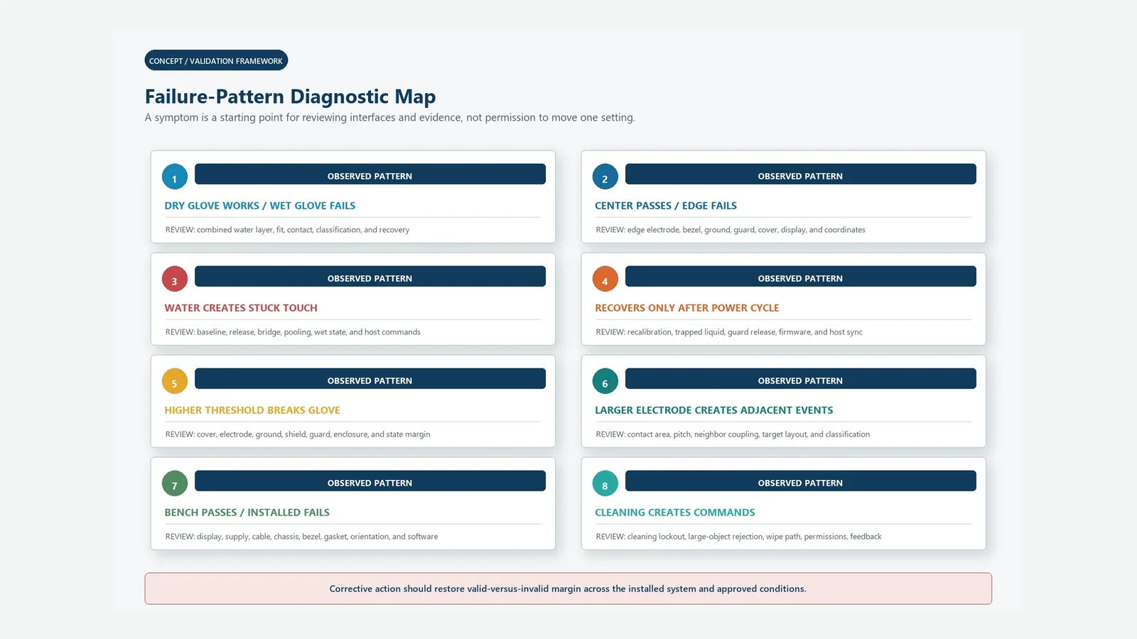
4. Use a Validation Matrix and Diagnose the Failure Chain
A validation matrix prevents a successful dry-glove demonstration from masking a wet-glove, edge, display-noise, or recovery failure. The sample quantity and acceptance method must come from project risk, applicable requirements, production variation, and the OEM quality plan—not from a generic blog number.
| Test group | Conditions to control | Results to record | Approval boundary |
|---|---|---|---|
| Dry bare finger | Operators/fixture, targets, center/edge, posture, gestures | Detect, coordinate/target, release, false event, feedback | Baseline interface behavior |
| Each dry glove | Exact model, size, layers, fit, temperature, posture | Weakest valid signal, misses, adjacent targets, repeatability | Only the listed glove articles |
| Wet finger | Liquid identity, application, target, movement, dwell | Accept/reject state, drag, second point, release, recovery | Defined wet-finger behavior |
| Wet glove | Exact glove plus wet method and dwell | Combined-state margin, wrong targets, lockout, recovery | Cannot be inferred from separate tests |
| Droplets/film/pooling | Placement, coverage, orientation, dwell, border path | Ghost events, wake, wet state, baseline, recovery | Water rejection behavior only |
| Runoff/wipe | Source, direction, speed, real cleaning material and liquid | Swipes, large-object handling, cleaning state, exit | Procedure-specific behavior |
| Display/power/EMI states | Brightness, refresh, startup, charger, motor, supply, cable | Noise, missed/false events, transitions | Installed electrical configuration |
| Assembly/change | Approved stack variations, lots, suppliers, firmware | Margin distribution, traceability, regressions | Released revision set |
When a test fails, follow the chain rather than immediately raising or lowering sensitivity.
| Observed failure | Likely chain to inspect first | Incomplete “quick fix” |
|---|---|---|
| Dry glove passes; wet glove fails | Wet layer → contact footprint → classification/state → threshold/recovery | Reusing dry-glove tuning |
| Center works; edge misses | Electrode/mesh edge → bezel/ground → cover registration → coordinate tuning | Enlarging every electrode |
| Water creates stuck touch | Bridge/pooling → baseline/release → guard/wet state → host permission | Power-cycle as normal recovery |
| Higher threshold rejects water but misses gloves | Insufficient margin → stack/geometry/noise/ground → state logic | One threshold compromise |
| Bench passes; enclosure fails | Display/power/chassis/cable → bezel/gasket → orientation/drainage | Repeating the coupon test |
| Wipe issues machine commands | Large moving object → cleaning state → host interlock → feedback | Faster debounce alone |
5. When Projected Capacitive Touch Is Not the Best Choice
Projected capacitive touch is not the best interface when the approved glove produces too little separable signal through the required lens, the liquid state overlaps valid input, or safe operation cannot tolerate uncertain classification or temporary lockout. It may also be unsuitable when a passive stylus, hard nonconductive tool, strong tactile confirmation, or operation under continuous uncontrolled liquid is mandatory.
In those cases, evaluate a resistive touch layer, sealed membrane switch, mechanical control, rotary input, or a hybrid HMI. The broader capacitive touch panel family can frame related stack options, but the correct choice depends on the task and failure consequence. Controller tuning should not be used to conceal a technology mismatch.
6. Project Input Checklist
Send this package before artwork, electrode routing, bonding, and tooling are frozen:
- [ ] Equipment task, operator, installation angle, reach, posture, and command consequence
- [ ] Bare-finger, wet-finger, glove, sleeve, palm, stylus, and invalid-object definitions
- [ ] Each glove manufacturer/model, material, size, layers, fit, condition, and wet method
- [ ] Droplet, condensation, film, runoff, pooling, wipe, cleaner, residue, and recovery definitions
- [ ] Button, slider, wheel, coordinate, gesture, multi-touch, edge, and inactive-area behavior
- [ ] Cover lens material, coating, finish, curvature, thickness, print, border, and approved supplier
- [ ] Adhesive/optical bond, coverage, local gap, bubble/void limits, and cure process
- [ ] Electrode pattern, pitch, traces, border, tail, connector, and registration drawings
- [ ] Display, PCB, power supply, cable, chassis, ground, shield, guard, bezel, gasket, enclosure, and drainage
- [ ] Controller, firmware owner, host owner, raw-data access, configuration version, and update method
- [ ] Detection, accuracy, false-event, release, lockout, feedback, recovery, and fault acceptance rules
- [ ] Prototype stages, approved sample plan, production variation, traceability, change triggers, and approval owners
This checklist turns capacitive touch water glove tuning into a reviewable engineering package. Missing items should be logged as open decisions rather than filled with supplier assumptions. Teams preparing drawings can also use JASPER’s technical resources and downloads route for controlled supporting documents; keep project-specific revisions in the approved release record.
7. Frequently Asked Questions
Can a capacitive glove touch panel work through a thick glove?
It can work when the exact glove, cover stack, electrode pattern, controller, ground, environment, and target are designed together. “Thick glove” is not a specification. Identify the manufacturer, model, size, layers, fit, fingertip construction, wet condition, posture, and required controls, then test that article on the installed stack.
Does increasing sensitivity solve glove operation?
Not by itself. A lower threshold or higher gain may expose a weak glove signal, yet it can reduce separation from water, sleeves, palms, display noise, edge coupling, and assembly variation. Use raw-data evidence to compare the weakest approved glove touch with the strongest invalid event before changing a setting.
What is water rejection capacitive touch?
Water rejection capacitive touch is defined system behavior when liquid is present without a valid user input. The system may ignore droplets, enter a wet state, restrict controls, or lock out input. It must also define entry, feedback, host permissions, exit, and recovery; it is not the same as an IEC 60529 rating.
Can projected capacitive touch support wet finger touch sensing?
Yes, if wet-finger input is a defined and validated state. Specify the liquid, application method, target, movement, surface condition, enclosure orientation, accepted coordinates, false-event limit, release, and recovery. A design that rejects unattended water does not automatically track a wet finger, and the reverse is also true.
Does a guard ring make a capacitive panel waterproof?
No. A guard channel can monitor a perimeter or liquid condition in selected controller architectures. Enclosure protection depends on the complete cover, seals, seams, fasteners, tail, connector, assembly, and IEC 60529 test configuration. Wet-operation performance still requires separate sensor, firmware, host, and recovery validation.
How should electrode size and pitch change for glove use?
They should be evaluated against the actual glove contact, visual target, cover stack, adjacent targets, edges, traces, controller method, and water bridges. A larger electrode may increase valid coupling and unwanted coupling. There is no universal size or pitch; compare candidate patterns using production-intent assemblies and retained measurements.
Why does a PCAP panel pass on the bench but fail in the enclosure?
The installed display, power supply, cable, chassis, ground, shield, bezel, gasket, fasteners, orientation, and drainage can change capacitance, noise, and liquid paths. A taped coupon omits those effects. Repeat validation with the production-intent stack, enclosure, power states, host software, and operator feedback active.
Is an IP-rated enclosure proof that touch works in rain?
No. IEC 60529 classifies enclosure protection under specified access, dust, and water tests. It does not define touch accuracy, false events, lockout, wet-finger tracking, or recovery during exposure. Wet usability and enclosure ingress protection need separate requirements, tests, configurations, and approval records.
What data should be saved during water and glove tuning?
Where the controller permits, save raw measurements, baseline, touch delta, noise, thresholds, hysteresis, detected and rejected states, guard/wet state, coordinates, response, release, and recovery. Tag each record with hardware, firmware, cover, sensor, display, enclosure, glove, liquid, orientation, environment, and power condition.
What should an OEM send before requesting capacitive touch water glove tuning?
Send the production cover-lens stack, electrode and target concept, exact gloves, liquid-state table, display and enclosure data, ground/shield/guard boundary, controller and firmware ownership, host behavior, and validation rules. That package lets the manufacturer identify missing decisions before artwork, bonding, electrode routing, and tooling are frozen.
8. Send the Cover Lens and Use Environment
For an engineering review, send the cover-lens drawing and material stack, target/electrode concept, exact glove ledger, liquid-state table, display and power details, enclosure orientation, ground/shield/guard plan, drainage path, controller boundary, and acceptance matrix. JASPER can be evaluated as one manufacturing option for the PCAP front-panel stack; the quotation should state who owns sensing design, tuning, firmware, fixtures, and installed-equipment validation.
Technical References
- Source: Texas Instruments CapTIvate Technology Guide. Accessed 2026.
- Source: Microchip AN2934 Capacitive Touch Sensor Design Guide. Accessed 2026.
- Source: Infineon AN85951 CAPSENSE Design Guide. Accessed 2026.
- Source: ISO 9241-210 Human-Centred Design for Interactive Systems. Accessed 2026.
- Source: IEC 60529 Degrees of Protection Provided by Enclosures. Accessed 2026.
- Source: IEC 60529. Accessed 2026.
- Source: Microchip AVR3002. Accessed 2026.
- Source: Microchip AN2934. Accessed 2026.
- Source: Infineon AN85951. Accessed 2026.
- Source: TI CapTIvate Design Guide. Accessed 2026.
- Source: TI TIDM-1021. Accessed 2026.
- Source: ISO 9241-210:2019. Accessed 2026.
- Source: Texas Instruments, *CapTIvate Technology Guide: Design Guide. Accessed 2026.
- Source: Texas Instruments, *TIDM-1021 Liquid-Tolerant Capacitive Touch Keypad Reference Design. Accessed 2026.
- Source: Microchip Technology, *AN2934 Capacitive Touch Sensor Design Guide. Accessed 2026.
- Source: Microchip Technology, *AVR3002: Moisture Tolerant QTouch Design. Accessed 2026.
- Source: Infineon Technologies, *AN85951: PSoC 4 and PSoC 6 MCU CAPSENSE Design Guide. Accessed 2026.
- Source: International Electrotechnical Commission, *IEC 60529 — Degrees of protection provided by enclosures (IP Code). Accessed 2026.
- Source: International Organization for Standardization, *ISO 9241-210:2019 — Human-centred design for interactive systems. Accessed 2026.
Tune water and glove behavior on the installed stack
Send the lens, glove ledger, liquid states, electrode concept, display, grounding, enclosure, controller, and acceptance matrix.