
Capacitive and resistive touch panels solve different input problems. Compare complete installed systems under the same glove, water, optical, controller, service, and validation conditions before selecting the interface.
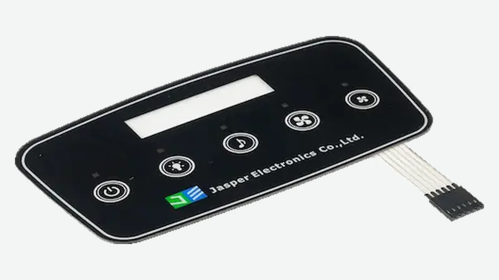
Capacitive vs Resistive Touch Panels at a Glance
This touch panel technology comparison uses conditional winners. A check mark means “start here and verify,” not “release the design without testing.” Short answer: PCAP wins modern gesture-led interfaces. Resistive wins defined pressure-input tasks. Wet, noisy, or safety-related equipment has no automatic winner because the enclosure, controller, and validation evidence set the boundary.
| Project requirement | Better initial candidate | Why | Condition that can reverse the choice |
|---|---|---|---|
| Rigid, continuous cover lens | PCAP | The electrode matrix can sense through a dielectric cover | Cover thickness, ink, adhesive, nearby metal, display noise, or grounding prevents adequate signal margin |
| Light bare-finger input | PCAP | No mechanical layer closure is required | Wet-state rejection, false-touch behavior, or accessibility targets are not met |
| Native multi-touch and pinch/rotate gestures | PCAP | PCAP controllers commonly resolve multiple electrode intersections | Host software, report rate, palm rejection, or edge performance is inadequate |
| Passive plastic stylus | Resistive | A local mechanical load can close the conductive layers | Tip geometry damages the surface or the required force is not repeatable |
| Thick or nonconductive glove | Resistive, or validated PCAP | Pressure is independent of glove conductivity; some PCAP systems support defined gloves | The actual glove, posture, target size, cover, and controller have not been tested together |
| Wet or washdown interface | No default winner | PCAP needs controlled wet-state behavior; resistive still needs sealing and wipe/ingress review | “Waterproof” is the only requirement and no liquid states are defined |
| Hard, scratch-resistant user surface | PCAP | A separate rigid cover can protect the sensor | Impact, coating, chemical, edge, or bonded-module service risks dominate |
| Legacy single-touch replacement | Often resistive | It may fit the existing controller and calibration model | Tail, active area, mapping, bezel support, or replacement lifecycle changes |
| Lowest total installed cost | No default winner | Hardware, controller, software, validation, service, and change control all matter | Purchasing compares loose-panel prices with different scopes |
The practical verdict is narrow: select PCAP for the interaction and surface architecture it enables; select resistive for a pressure-input requirement it satisfies. If the requirement is merely “industrial,” neither label is enough.
JASPER’s capacitive touch panels are one route for projects that proceed with a capacitive front-panel architecture. The comparison below does not imply that JASPER supplies every resistive construction described.
Define Equivalent Touch Systems Before Comparing
A useful projected capacitive vs resistive touch review begins with equivalent system boundaries. In this guide, capacitive means Projected Capacitive Touch: an electrode-based coordinate sensor used with a display, not a single capacitive button. Resistive means Analog Resistive Touch: a coordinate panel in which pressure brings conductive layers into contact; common versions include 4-Wire Resistive and 5-Wire Resistive panels.
The two signal chains are different:
PROJECTED CAPACITIVE (PCAP)
input object
dielectric cover lens and printed mask
adhesive, optical bond, or controlled gap
patterned electrode matrix and tail
PCAP controller and configuration
mapped coordinates / gestures
display, host software, enclosure, and ground
ANALOG RESISTIVE
input object and local force
flexible conductive top sheet
spacer gap and lower conductive layer
tail and resistive controller / ADC
filtering and calibration transform
mapped coordinate
display, host software, bezel, and enclosure
Microchip Technology’s AN2934 Capacitive Touch Sensor Design Guide, revision B dated 2020, treats the cover, electrode geometry, shielding, nearby ground, Signal-to-Noise Ratio, and moisture as connected design inputs. The cover is therefore an electrical component of a PCAP system, even when it carries Graphic Overlays and protects the Display Module.
A resistive system converts a local mechanical event into an analog coordinate. Microchip’s AN8091 Four and Five-Wire Touch Screen Controller, revision 8091A-AVR-07/07, describes controller interfacing for common 4-wire and 5-wire touchscreens. The controller changes how it excites and reads the panel to match the construction. That 19-page source supports the operating principle; it does not make one controller circuit universal.
Scope errors produce misleading comparisons. A bare sensor lacks the cover, controller, display, grounding, enclosure, firmware, and validation included in a production HMI. A bonded module includes many of those items. Compare quotations and samples at the same boundary, with the same drawing revision and acceptance criteria.
Input Method: Finger, Glove, and Stylus
Input-object choice often settles the first prototype route, but only after the object is defined. “Gloved operation” is not a test condition. Nitrile, insulated work gloves, wet fabric, layered cold-weather gloves, and a conductive fingertip present different electrical coupling, force transfer, posture, and target-access conditions. Microchip Technology, Texas Instruments, and Infineon document those variables as controller-and-sensor design inputs rather than universal touch-panel properties.
| Input object | PCAP design question | Resistive design question |
|---|---|---|
| Bare finger | Can the controller resolve valid touches through the final cover at the center, edges, and corners? | Can the operator close the layers without excessive force or visible surface deflection? |
| Thin glove | Does the production stack retain enough signal margin without increasing false touches? | Does the glove transfer repeatable local load at the required target size? |
| Thick nonconductive glove | Does the selected controller support the exact glove, cover, and grounding condition? | Can the operator actuate repeatedly with the expected posture and support stack? |
| Passive plastic stylus | Usually not a finger-equivalent input; use only if the system is designed for it | Often suitable as a pressure input after tip-load and wear review |
| Conductive or active stylus | Must match the controller, sensor, protocol, cover, and palm strategy | Pressure input may work, but active-stylus features are a separate requirement |
| Fingernail or tool tip | Not a dependable PCAP input by itself | May close the layers, but sharp tips can create concentrated surface stress |
Commercial PCAP controller families such as Microchip Technology’s maXTouch advertise Glove Mode, Moisture Resilience, Multi-Touch, and Noise Management. Infineon Technologies’ AN85951 CAPSENSE Design Guide, revised May 26, 2026, likewise treats Overlay Design, Signal-to-Noise Ratio, Shield Electrode, Guard Sensor, tuning, and liquid behavior as one design problem. These are platform capabilities—not proof that an arbitrary panel will work through an arbitrary glove.
Resistive touch is not “compatible with every glove.” It needs enough localized force to close the sensor without unacceptable fatigue, missed input, bezel interference, or damage. A thick glove may transfer force well yet make a small target hard to reach. Test the glove model, size range, wet and dry condition, operator posture, target dimensions, and rear support together.
PCAP is not the best choice when the product must accept a fine passive stylus or unpredictable nonconductive gloves and the team cannot validate a PCAP controller mode for those inputs. Resistive is not the best choice when users expect effortless multi-touch gestures through a hard continuous cover.
Water Behavior Is a Test Requirement, Not a Label
Neither sensing principle makes a finished interface waterproof. Water can alter a PCAP electrode field; it can also enter a resistive panel, load its surface during wiping, contaminate an edge, or reach the tail and connector. The required behavior must be written before the supplier chooses a sensor or controller. Droplets are one state. Runoff is another. Pooled cleaner is a third, and each state can demand a different response.
Texas Instruments’ CapTIvate Design Guide distinguishes Moisture-Tolerant Operation from Spill Rejection. A Guard Channel can detect broad liquid coverage and suppress normal Touch Sensor reporting. That behavior is different from tracking a Wet Finger, accepting touches under Droplets, or continuing operation beneath Pooled Liquid.
Define each state separately:
| Liquid state | Possible required behavior | Evidence to collect |
|---|---|---|
| Isolated droplets | Accept valid touches and reject droplets, or lock the interface | Coordinate logs, false/missed touches, recovery after drying |
| Continuous film | Continue, reject all input, or allow selected controls only | Film composition, coverage, orientation, duration, controller state |
| Wet finger | Track the finger without a persistent false point | Center/edge coordinates, release behavior, repeated touches |
| Wet glove | Accept or reject the named glove intentionally | Glove model, saturation method, target size, posture, repeated trials |
| Moving runoff | Reject moving liquid while preserving defined controls | Flow path, rate, bezel path, orientation, recovery |
| Cleaning wipe | Avoid unintended commands or enter a cleaning lockout | Wipe material, chemical, force, pattern, lockout/re-enable sequence |
| Pooled liquid | Usually lock out or enter a defined safe state | Pool depth/area, duration, fault indication, dry recovery |
| Ingress exposure | Preserve the enclosure’s required protection and post-test function | Complete assembly, seal, tail exit, connector, test method |
For PCAP, include the final cover, adhesive or optical bond, display, power supply, charger if applicable, chassis, ground path, cable, firmware revision, and controller configuration. A development board under a clean glass coupon cannot validate the production stack.
For resistive touch, define surface load from wipes and liquid movement, edge-seal exposure, contamination, top-sheet damage, optical changes, connector exposure, and post-cleaning calibration. Surface droplets may not resemble an internal layer-contact event, but the full product still has mechanical and ingress failure paths.
IEC 60529 classifies protection provided by an enclosure. It does not grant an IP Code to a loose touch sensor, cover lens, adhesive, or gasket. Any IP claim needs the complete evaluated enclosure, assembly process, orientation, sample condition, acceptance criteria, and post-test inspection.
Optical Quality, Cover Lens, and Mechanical Stack
PCAP often produces the cleaner industrial design: a rigid glass or polymer cover can span the display and printed border without a user-flexed sensor surface. That does not justify a universal optical-transmission claim. Reflection, haze, contrast, parallax, color shift, electrode visibility, coatings, bonds, air gaps, masks, display luminance, and viewing angle belong to the complete stack.
| Stack item | PCAP review | Resistive review |
|---|---|---|
| User surface | Cover material, strengthening, finish, coating, print, curvature | Flexible top-film material, finish, coating, deflection, scratch condition |
| Internal interfaces | Cover bond/gap, sensor carrier, electrode pattern, display bond | Top sheet, spacer structure, lower substrate, panel-to-display bond/gap |
| Registration | Sensor active area, display active/visible areas, black mask, edge targets | Touch active/border areas, bezel opening, display mapping, tail orientation |
| Mechanical support | Cover edge support, adhesive stress, display clearance, enclosure datums | Bezel preload, rear support, layer movement, edge-seal compression |
| Optical approval | Final stack under required lighting, angle, display state, and surface condition | Final stack under the same conditions plus defined input load and wear state |
AN2934 explains why increased Cover Lens thickness reduces capacitive signal unless Electrode Geometry and Touch Controller electronics compensate. Conductive Ink, Metal Bezel, Ground Plane, Air Gap, and Optical Adhesive changes can alter coupling. For a design that needs a rigid front, review the intended PCAP touch panels as part of the Cover–Display–Enclosure stack—not as a separate catalog item.
Resistive touch deliberately depends on top-sheet movement. Bezel pressure, uneven support, local preload, or a poorly controlled opening can affect contact and edge behavior. A replaceable panel may simplify service in one product; an exposed flexible surface may create the dominant cosmetic or wear risk in another.
Compare approved production-intent stacks using the same display image, luminance, ambient lighting, viewing geometry, cleaning state, and acceptance method. Supplier brochure percentages from unlike constructions are not an engineering comparison.
Durability Means Failure Mode Plus Use Profile
PCAP has no internal contact closure on every touch, but the complete assembly can still fail through a scratched or cracked cover, coating wear, print damage, adhesive separation, tail fatigue, connector faults, display stress, controller damage, or electrical noise. Resistive panels add repeated top-sheet flexing and conductive-layer contact, yet their useful life also depends on construction and use.
A defensible durability requirement names the mechanism and exposure:
| Failure area | PCAP examples | Resistive examples |
|---|---|---|
| User surface | Scratch, coating wear, impact crack, chemical attack | Scratch, cut, dent, coating wear, permanent top-film deformation |
| Sensing path | Electrode, tail, bond, connector, or controller fault | Conductive-layer wear, unstable contact, spacer, tail, or controller fault |
| Installed mechanics | Cover stress, adhesive creep, display contact, edge damage | Bezel preload, poor rear support, layer-gap change, edge-seal damage |
| Coordinate behavior | Edge error, baseline shift, false or missed touch | Calibration shift, edge nonlinearity, intermittent contact |
| Environment | Moisture coupling, condensation, ground change, ESD damage | Ingress, contamination, film-property change, ESD at electrical paths |
| Service | Bonded-module replacement, configuration mismatch, obsolescence | Replacement-panel fit, recalibration, connector/controller mismatch |
The failure chain is often managerial before it becomes physical:
vague input or environment requirement
supplier selects a convenient stack
controller and enclosure change after tuning
sample passes a dry bench demonstration
production variation reduces margin
wet, gloved, edge, or noise failures appear in the installed unit
Replace the question “How many touches does it last?” with a use profile: contact object, tip geometry, force where relevant, stroke path, high-use locations, cleaning agent, wipe material, temperature/humidity states, contamination, impact, accepted cosmetic change, coordinate-drift limit, maintenance, and replacement policy. A catalog cycle count from a different stack cannot answer that requirement.
PCAP is not necessarily the durable choice when a rigid cover faces severe impact and the only service unit is an expensive bonded display module. Resistive is not necessarily disposable; it may be the controlled field-replaceable part in a legacy product. Durability belongs to the architecture and service boundary.
Controller, Calibration, Multi-Touch, and Noise
A touch panel without a controlled controller configuration is unfinished. PCAP and resistive systems need different signal processing, but both require named owners for electronics, settings, coordinate mapping, software behavior, revisions, diagnostics, and component changes. Record those names. Freeze the revisions. A supplier sample that works today is not configuration control.
PCAP controller responsibilities
A PCAP controller scans electrodes and separates intended coupling changes from Baseline Drift, Display Noise, Power Noise, Metal Bezel effects, Ground Variation, Moisture, Gloves, Edge Effects, Sleeves, Palms, and unintended Large Objects. Microchip Technology AN2934, Microchip Technology maXTouch documentation, and Infineon Technologies AN85951 all show why Touch Controller capability, Sensor Geometry, Cover Stack, Shielding, and tuning cannot be selected independently.
The released configuration should identify at least:
- controller part and firmware/configuration revision;
- sensor map, channels, scan modes, and report interface;
- baseline, threshold, hysteresis, and noise strategy;
- glove and wet-mode entry/exit behavior;
- shield, guard, chassis, and ground assumptions;
- edge, bezel, palm, sleeve, and large-object handling;
- coordinate orientation, active area, and display mapping; and
- fault reporting, update method, and configuration owner.
Resistive controller responsibilities
A common Analog Resistive Touch Controller excites the panel, measures Contact Voltage, determines whether contact is valid, filters samples, and maps Raw Coordinates to the Display Coordinate System. Cable Resistance, ADC Settling, Touch Pressure, panel orientation, production variation, and Display Alignment can all affect the reported point.
Analog Devices’ Touchscreen Calibration explanation describes Coordinate Transformation between Touch-Panel and Display spaces, including Translation, Rotation, and Scaling effects. Calibration Data therefore needs an owner, storage location, production method, service procedure, and change rule.
Multi-touch and gesture boundary
Native multi-touch is a core PCAP advantage. A matrix and suitable controller can resolve multiple touch points, while host software decides what pinch, rotate, drag, palm rejection, and simultaneous commands mean. The number of reported contacts alone does not validate target separation, edge gestures, latency, or unintended-contact rejection.
Common 4-wire and 5-wire analog resistive systems are usually implemented as one coordinate at a time. Two contacts can combine into an ambiguous electrical result. Still, “resistive can never recognize a gesture” is too broad: Analog Devices documented gesture recognition on a conventional 4-wire resistive touchscreen using a specialized controller method. That exception does not make an ordinary resistive panel equivalent to a PCAP multi-touch matrix.
Electrical noise is a system issue
PCAP measures small field changes, so display drive, power conversion, charging, cables, communication buses, metalwork, shield design, and ground references can consume signal margin. Resistive touch begins with mechanical contact, but its controller still measures analog voltage and remains exposed to display interference, cable pickup, ESD paths, reference errors, and host-interface faults.
For either technology, test the production display in all operating states, the intended power supply, the longest approved cable, the installed enclosure, communications activity, grounding variants, and defined disturbances. “Capacitive is noise-sensitive” and “resistive is noise-immune” are slogans, not acceptance criteria.
Total Cost Depends on Integration and Service
A loose resistive panel may have fewer optical and controller-integration demands in one design. A PCAP assembly may remove mechanical openings, support a common cover family, and enable the interaction model the software already needs. Neither observation establishes a universal cost winner.
| Cost block | PCAP questions | Resistive questions |
|---|---|---|
| Touch hardware | Cover, sensor, tail, controller, shield, bond | Panel construction, tail, controller, bezel, support |
| Display integration | Mask, registration, optical/perimeter bond, noise coupling | Registration, border, gap/bond, support, calibration |
| Electronics/software | Configuration, gestures, glove/wet states, diagnostics | Excitation, ADC/filtering, coordinate mapping, calibration UI |
| Tooling and samples | Cover decoration, sensor, fixtures, tuning builds | Panel tooling, spacer/contact construction, fixtures, calibration builds |
| Validation | Input objects, water states, noise, edge, enclosure, ESD | Force/stylus, wear, calibration, water, enclosure, ESD |
| Field service | Bonded-module policy, configuration control, display lifecycle | Surface replacement, recalibration, tail/controller compatibility |
| Change control | Cover, display, adhesive, controller, firmware, ground | Panel, tail, controller, support, display mapping, calibration |
Quote the same deliverable boundary and quantity. Include nonrecurring engineering, samples, controller/firmware work, fixtures, display integration, validation, production programming, calibration, yield criteria, packaging, spares, replacement labor, and revalidation after change. A panel-price comparison cannot settle total cost.
The lowest-risk route may also be the lower-cost route even when its sensor price is higher. Conversely, a sophisticated PCAP stack is wasteful when the interface only needs one pressure coordinate and a fine passive stylus.
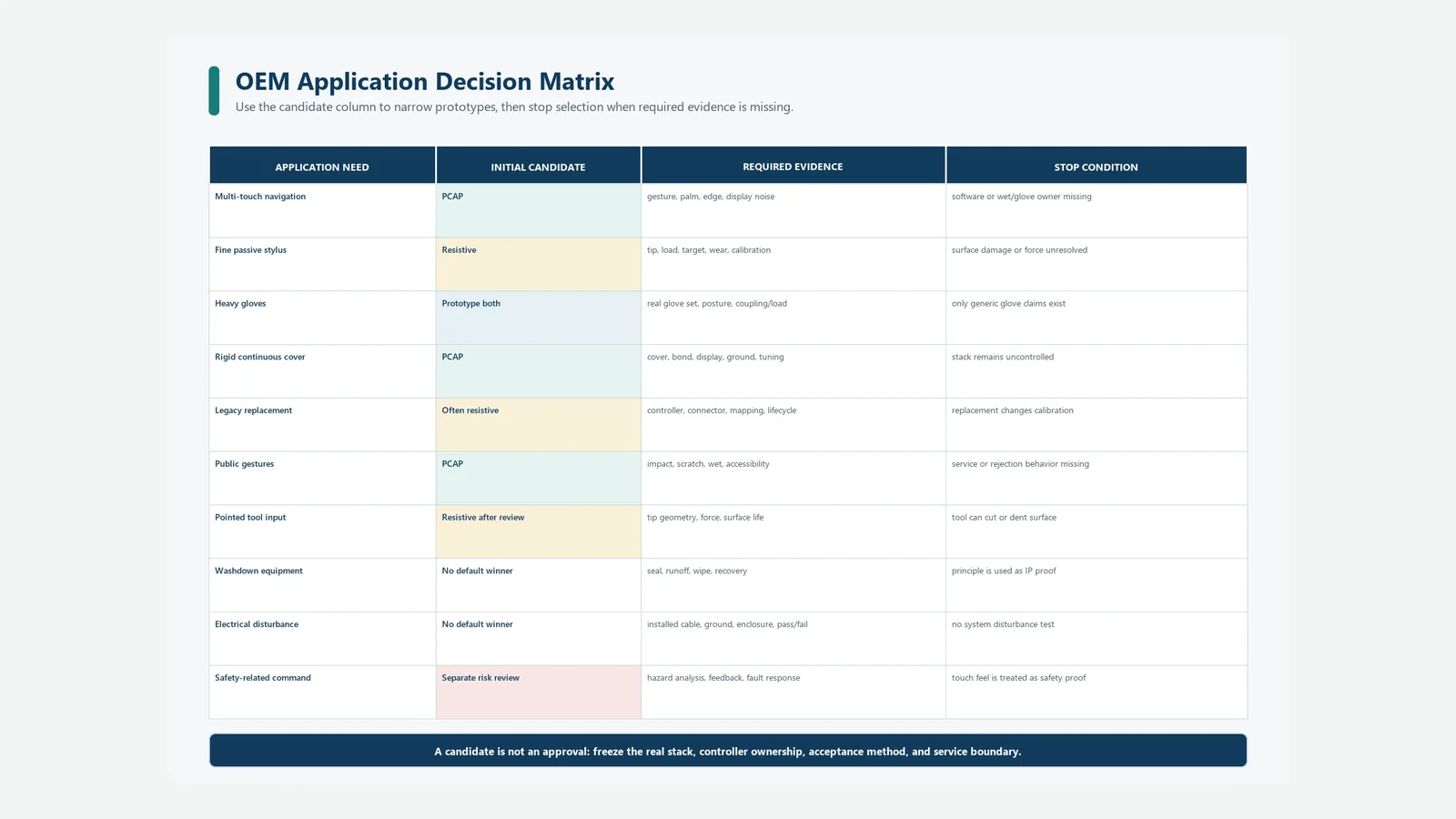
Industrial Touch Selection Decision Matrix
Industrial touch selection should begin with tasks and failure consequences, not the word “industrial.” The matrix below identifies a prototype candidate and the condition that blocks design freeze.
| Application need | Initial candidate | Engineering reason | Do not freeze the choice when… |
|---|---|---|---|
| Multi-touch display navigation | PCAP | Direct path to multiple coordinates and familiar gestures | Glove, wet, edge, noise, palm, or software ownership is unresolved |
| Fine passive-stylus data entry | Resistive | Local pressure can create a small coordinate | Tip wear, required load, calibration, or target accessibility is unresolved |
| Heavy, variable gloves | Resistive or validated PCAP | Choice depends on force transfer versus electric coupling | The real glove set and operator posture are unavailable |
| Continuous rigid cover | PCAP | Sensor can operate behind a separate dielectric front | Cover, bond, display, metalwork, ground, and controller are not frozen |
| Legacy single-touch HMI replacement | Often resistive | May preserve controller and application assumptions | Active area, tail, mapping, bezel support, or lifecycle differs |
| Public terminal with gestures | PCAP | Supports multi-touch interaction through a hard cover | Impact, scratching, wet use, palm, accessibility, or service is unresolved |
| Frequent pointed-tool input | Resistive after wear review | Nonconductive tips can apply pressure | Tip geometry or force threatens the surface |
| Wet or washdown equipment | No default winner | Wet behavior and enclosure sealing require separate evidence | Sensing principle is being used as proof of ingress protection |
| Severe electrical-noise environment | No default winner | Controller, cable, display, power, enclosure, and ground decide | No installed-system disturbance test exists |
| Safety-related command | Neither without system risk controls | Touch technology alone does not provide safety integrity | The design treats appearance, tactile absence, or controller marketing as a safety function |
For industrial control interfaces, the right answer can be “neither.” Examples include a safety-related action that requires a separate rated control path, an operator task that needs confirmed tactile feedback, or a wet or gloved condition failed by both prototypes. A physical key, membrane switch, guarded control, rotary input, or mixed HMI may carry that function more safely.
Use the matrix to select prototypes, not to approve production. A real decision also includes hazard analysis, accessibility, operator training, cleaning, maintenance, cybersecurity where configuration is updateable, and equipment-level regulatory obligations.
Installed-System Validation Matrix
Validation must use production-intent hardware. A loose sensor demonstration omits cover print, bond, display noise, bezel, rear support, ground, cable, firmware, host timing, and the environment that determines field behavior.
| Test condition | PCAP evidence | Resistive evidence | Shared acceptance record |
|---|---|---|---|
| Bare finger | Detection, edge/corner accuracy, release, invalid objects | Required load, coordinate, edge behavior, repeatability | Input object, target map, misses, false events, coordinate errors |
| Defined gloves | Valid/invalid input, mode changes, bare-finger coexistence | Load, target access, fatigue, surface stress | Glove make/model/size, dry/wet state, posture, sample revision |
| Stylus | Supported type, palm behavior, edge and line tracking | Tip shape, load, line/point behavior, wear | Stylus ID, angle, force method, drawing path, surface inspection |
| Liquid states | Droplet, film, runoff, wet finger/glove, lockout, recovery | Wipe/load events, ingress, contamination, recovery | Liquid/chemical, volume or coverage, orientation, duration, pass/fail mode |
| Display states | Noise and coordinates in every display/power mode | Calibration and interference in every display/power mode | Display, power, image patterns, communications, logging |
| Installed enclosure | Metal, bezel, cover bond, ground, cable, service fit | Bezel preload, support, tail, seal, layer movement | Assembly work instruction, torque/compression, datums, photos |
| Environment | Baseline and modes through temperature/humidity/condensation states | Film/contact/calibration/seal behavior | Preconditioning, dwell, operating state, recovery, damage |
| Electrical disturbance | False/missed touch, lockup, reset, damage, recovery | Coordinate stability, false event, reset, damage, recovery | Standard/method if applicable, setup, performance criterion, logs |
| Surface use | Scratch, coating, impact, chemical, bond | Scratch, flex/contact wear, stylus and wipe exposure | Use profile, inspection criteria, functional retest |
| Replacement/change | Configuration and interchangeability | Mechanical fit, mapping and recalibration | Changed part/revision, data restore, revalidation scope |
ISO 9241-210:2019, Edition 2 published in July 2019 and confirmed current on May 22, 2025, places Human-Centred Design across the lifecycle of Interactive Systems. Apply that principle by testing real tasks: posture, reach, Target Size, Gloves, Stylus, lighting, feedback, Error Recovery, cleaning, and service—not coordinate output alone.
JASPER’s testing and validation capabilities can be reviewed when defining the supplier-side evidence boundary. The quotation and control plan still need to state which tests JASPER performs, which tests the controller or display supplier performs, and which installed-equipment tests remain with the OEM. This article claims no specific accreditation or result.
OEM Drawing and Sample-Approval Checklist
Send one controlled input package before asking a supplier to choose the architecture:
- Display drawing: outline, active area, visible area, orientation, connector, mounting, and display-driving conditions.
- Interaction definition: single touch, multi-touch, gesture, drawing, signature, data entry, fixed controls, target map, and feedback.
- Input objects: each finger posture, glove make/model/size, stylus or tool, and objects that must be rejected.
- Front surface: material, thickness, finish, coating, print, curvature, bond, mask, cosmetic zone, and cleaning method.
- Enclosure section: bezel opening, material, datums, support, gasket, fasteners, rear depth, tail route, connector, and service access.
- Electronics: controller, PCB/FPC, power, communications, display, ground, shield, firmware, diagnostics, updates, and configuration owner.
- Environment: dry/wet states, liquid chemistry, condensation, contamination, temperature, humidity, vibration, impact, storage, and cleaning.
- Acceptance criteria: coordinate error, edge zone, repeatability, response, false/missed touch, recovery, optical inspection, and allowed cosmetic change.
- Lifecycle: use profile, replacement unit, recalibration, approved alternates, spare policy, obsolescence, and change control.
- Evidence plan: prototype stages, sample quantity, test matrix, traceability, production volume, approval owners, and revalidation triggers.
Approval should identify the cover, sensor/panel, display, controller, firmware/configuration, enclosure, adhesive/bond, cable, and test procedure by revision. A golden sample without that configuration record cannot control later substitutions.
Request a Touch-Panel Design Review
A useful design review starts with the display drawing, enclosure section, cover concept, input objects, interaction model, controller plan, wet states, ground strategy, service unit, and validation matrix. Submit that package to request a touch-panel design review.
JASPER can assess whether a capacitive front-panel route fits the stated boundary and identify unresolved controller, cover, display, enclosure, or test inputs. Resistive supply scope must be confirmed separately; this guide does not present it as a verified JASPER offering.
Frequently Asked Questions
Is capacitive touch better than resistive touch?
No universal winner exists. Projected Capacitive Touch is the stronger candidate for a rigid cover, light finger input, native multi-touch, and gestures. Analog Resistive Touch is stronger when a defined glove or passive stylus must create a coordinate by pressure. Water, durability, accuracy, sealing, and total cost still require installed-system evidence.
Do resistive touch panels work with every glove?
No. A resistive panel needs enough local force to close its conductive layers. Glove thickness, stiffness, grip, operator posture, target size, top-sheet behavior, and rear support affect repeatability. Test every required glove model and size in dry and wet states rather than approving gloved operation as one condition.
Can projected capacitive touch work with thick gloves?
Yes, some PCAP controllers support defined glove modes, but the result depends on the actual glove, cover, electrode geometry, controller, tuning, display noise, ground, moisture, and enclosure. A controller-family feature is not a finished-product guarantee. Validate glove and bare-finger behavior together on production-intent hardware.
Which touch technology is better in water?
Neither has a default win. PCAP must distinguish wet-finger tracking, droplet rejection, spill lockout, and dry recovery. Resistive input starts with pressure, but wiping, ingress, contamination, edge seals, tails, and connectors still matter. Define liquid, coverage, orientation, required response, and enclosure test before selecting.
Does PCAP always have better optical quality?
No. PCAP often supports a rigid, integrated front, while resistive commonly adds a flexible conductive sheet and internal interfaces. Actual optical quality depends on cover or film, coatings, electrodes, bonds, gaps, display, lighting, viewing angle, wear, and test method. Compare complete production-intent stacks under identical conditions.
Are resistive touch panels limited to single touch?
Common analog 4-wire and 5-wire systems are normally used as one coordinate at a time. Specialized controllers can infer selected two-contact gestures, as Analog Devices demonstrated, but that is not equivalent to a PCAP matrix reporting multiple independent points. Require controller-specific evidence for every gesture.
Which technology lasts longer?
There is no credible universal answer without a use profile. PCAP removes repeated internal contact but can fail through its cover, bond, tail, controller, or bonded-module service boundary. Resistive adds top-sheet flex and contact wear but may be field-replaceable. Specify contact objects, locations, cleaning, chemicals, impact, accepted drift, and maintenance.
What should an OEM send for a touch-panel design review?
Send the display drawing, interaction and target map, glove/stylus list, cover specification, enclosure section, controller and grounding plan, wet and environmental states, acceptance criteria, service boundary, production volume, change-control rules, and test matrix. State whether the requested deliverable is a sensor, bonded display, or complete front-panel assembly.
Technical References
- Source: Microchip AN2934 Capacitive Touch Sensor Design Guide. Accessed 2026.
- Source: Texas Instruments CapTIvate Technology Guide. Accessed 2026.
- Source: Microchip AN8091 Four and Five-Wire Touch Screen Controller. Accessed 2026.
- Source: Analog Devices Touch-Screen Calibration Guidance. Accessed 2026.
- Source: ISO 9241-210 Human-Centred Design for Interactive Systems. Accessed 2026.
- Source: IEC 60529 Degrees of Protection Provided by Enclosures. Accessed 2026.
- Source: AN2934 Capacitive Touch Sensor Design Guide. Accessed 2026.
- Source: AN8091 Four and Five-Wire Touch Screen Controller. Accessed 2026.
- Source: maXTouch. Accessed 2026.
- Source: AN85951 CAPSENSE Design Guide. Accessed 2026.
- Source: CapTIvate Design Guide. Accessed 2026.
- Source: 60529. Accessed 2026.
- Source: Touchscreen Calibration explanation. Accessed 2026.
- Source: gesture recognition on a conventional 4-wire resistive touchscreen. Accessed 2026.
- Source: 9241-210:2019. Accessed 2026.
- Source: AN2934: Capacitive Touch Sensor Design Guide. Accessed 2026.
- Source: CapTIvate Technology Guide — Design Guide. Accessed 2026.
- Source: AN8091: Four and Five-Wire Touch Screen Controller. Accessed 2026.
- Source: An Easy-to-Understand Explanation of Calibration in Touch-Screen Systems. Accessed 2026.
- Source: Gesture Recognition on Resistive Touch Screens. Accessed 2026.
- Source: maXTouch Technology Overview. Accessed 2026.
- Source: AN85951: PSoC 4 and PSoC 6 MCU CAPSENSE Design Guide. Accessed 2026.
- Source: ISO 9241-210:2019. Accessed 2026.
- Source: IEC 60529, Edition 2.2. Accessed 2026.
Select the touch architecture from the operating states
Send the display, input objects, cover stack, wet states, controller boundary, enclosure, service plan, and acceptance matrix.