
Silicone keypad sealing design is an enclosure decision, not a rubber-part claim. For industrial, marine, medical, and vehicle-equipment teams specifying silicone keypad assemblies, the job is to define the ingress target, control perimeter compression, and test the production-intent assembly—including its fasteners, joints, vents, connectors, and cable entries. A loose keypad cannot establish the enclosure's IP rating.
JASPER certifications: ISO 9001, ISO 13485, IATF 16949, and ISO 14001.
A successful design creates one continuous, controlled barrier between the wet or dusty environment and the protected electronics. This guide shows what belongs on the drawing, where load must travel, how to expose weak links before tooling approval, and when a molded keypad perimeter is the wrong sealing method. It does not assign a universal squeeze percentage or replace the current edition of the governing standard.
1. Silicone Keypad Sealing Design Starts With the Rating
The first decision is not bead shape. It is the protection requirement for the assembled enclosure. IEC 60529 classifies the protection provided by enclosures against access to hazardous parts, solid foreign objects, and water ingress. The first IP numeral addresses solids/access; the second addresses water. IP6X, IPX7, and IP67 are therefore different statements, not interchangeable shorthand for “waterproof.”
This distinction matters for a waterproof rubber keypad. A keypad supplier can characterize a molded part, a material, or a subassembly. Only a representative equipment build shows whether water bypasses the keypad flange, follows a cable, crosses the housing split, enters through a vent, or passes a connector interface. A component claim never closes those other routes.
Write these inputs before discussing tooling:
| Design input | State it explicitly | Why it changes the seal |
|---|---|---|
| Governing method | IEC 60529, NEMA 250, ISO 20653, or customer method; include edition | Test apparatus, exposure and acceptance rules differ |
| Required protection | Complete designation, not “weatherproof” | Solids, water jets, immersion and other conditions are separate |
| Installation | Orientation, handheld/panel-mounted, indoor/outdoor, elevation | Drainage, pooling and pressure behavior change |
| Service exposure | Water, dust, salt, cleaners, oils, UV, temperature range | Material and secondary openings may control the result |
| Duty state | Powered/unpowered, buttons operated or static | Actuation can move the sealing flange or change internal pressure |
| Acceptance | Water-location rule, insulation/function checks, allowable cosmetic change | “No failure” is not a measurable criterion |
For marine and outdoor equipment, include wash direction, standing-water risk, freeze/thaw condition, solar load, salt exposure, and drainage. ASTM B117 supplies a salt-fog apparatus practice; it does not convert a chosen number of exposure hours into field life.
The requirement names the governing document and exact protection designation, then lists orientation, conditioning, operational state, inspection method, and acceptance criteria.
The purchase specification asks for “IP67 material” or “waterproof silicone” without defining the complete equipment assembly.
2. Map Every Opening in the Sealed Keypad Enclosure
A sealed keypad enclosure is a network of boundaries. Draw that network before optimizing the keypad. The review should include the keypad perimeter, upper/lower housing joint, display lens, speaker membrane, service door, fasteners that penetrate the wall, cable glands, connectors, vents, and any molded-in inserts.
The boundary map also fixes ownership. The enclosure designer controls flange stiffness and boss geometry. The keypad designer controls molded sealing features and interface dimensions. Assembly engineering controls cleanliness, sequence, torque or displacement, and inspection. The validation team controls the representative build and declared method. Splitting these decisions across unconnected drawings creates gaps.
Teams evaluating silicone keypad assemblies should ask for the keypad, carrier or PCB, enclosure, and retaining features to be reviewed as one stack. This link appears early because assembly architecture must be settled before the silicone tool is frozen.
| Boundary element | Primary control | Evidence needed before release | Typical hidden bypass |
|---|---|---|---|
| Keypad perimeter | Molded bead or gasket land under controlled compression | Section drawing plus worst-case stack | Corner lift or flange deflection between screws |
| Housing split | Separate gasket, weld, adhesive or molded seal | Joint specification and assembly record | Keypad passes while the case seam leaks |
| Cable entry | Selected gland/grommet matched to cable OD | Current datasheet and installed-sample test | Wrong cable diameter or side load |
| Pressure vent | Membrane, housing interface and adhesive/mounting process | Selected-part data and integration test | Liquid path around the vent perimeter |
| Connector | Rated mated pair plus panel seal | Mating/installation instructions and test state | Test run with cap fitted but field use uncapped |
| Fastener penetration | Blind boss, sealing washer or sealed insert | Section and assembly instruction | Helical path along thread or cracked boss |
| Display/window | Bond line or compressed gasket | Bond/gasket specification and conditioning | Peel at corner or coating contamination |
| Service access | Door gasket and latch compression | Latch tolerance and maintenance instruction | Uneven compression after repeated opening |
One marked-up section or boundary diagram names the seal owner, drawing reference, and verification method for every penetration.
The keypad is labeled IP67, while cable, vent, display, and case-joint responsibility remains “not yet defined.”
3. Choose the Seal Architecture Before Detailing the Bead
A molded perimeter bead is often effective because the keypad can provide both the user interface and the silicone keypad gasket in one part. That is not the only valid architecture. The choice should follow enclosure stiffness, serviceability, available flange width, contamination, assembly access, cosmetic constraints, and production volume.
| Architecture | Best fit | Main control | Main limitation |
|---|---|---|---|
| Molded perimeter bead on keypad | Compact HMI with a continuous, clampable flange | Bead geometry, compression stops, enclosure flatness | Tooling locks the interface; weak housings can distort |
| Broad molded sealing flange | Large contact land and low local pressure | Flatness, retention and anti-wicking features | Can wrinkle or creep if not positively retained |
| Separate die-cut gasket | Keypad and enclosure need independent service or materials | Gasket thickness, cut geometry, registration | Extra part, extra tolerance and assembly step |
| Liquid-dispensed gasket | Irregular housing path with controlled dispensing process | Bead volume, cure, adhesion and path continuity | Process qualification and rework can be difficult |
| Structural adhesive or tape seal | Thin package with compatible, stable bond surfaces | Exact adhesive, preparation, dwell and peel geometry | Bond aging and service removal need separate proof |
| Overmolded carrier or two-shot interface | High integration and controlled production scale | Material compatibility and molding process | Higher tooling/process commitment; repair is limited |
The molded-bead approach is not the best choice when the enclosure cannot supply a stiff, continuous land; when regular field service must separate the keypad from the housing; when the required chemistry is outside the selected silicone compound's verified resistance; or when the bezel cannot provide positive retention. A separate gasket, bonded window/keypad construction, welded enclosure, or isolated boot may be easier to control.
Adhesive should not be treated as invisible mechanical compression. Industrial tapes and liquid adhesives have product-specific limits for surface energy, preparation, bond-line thickness, temperature, fluids, peel and creep. If adhesive is the primary environmental barrier, name the exact product and application process, then validate aged assemblies. “3M or equivalent” is not an engineering specification.
Likewise, a cosmetic skirt around silicone rubber keypads may improve appearance or shed splash without functioning as the main seal. The section drawing must show where contact pressure closes the path.
The architecture table records why the selected seal fits the flange, load path, service plan, process and environment.
The seal type is chosen because it worked on a different enclosure with different stiffness, span and material.
4. Build the Compression Stack From Worst-Case Geometry
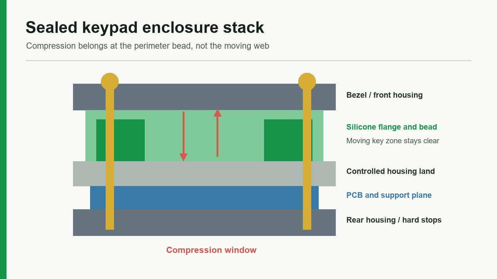
Compression is a displacement problem before it is a torque problem. The designer needs the free height of the molded bead, the closed distance between its mating surfaces, all relevant tolerances, local housing deflection, and the selected compound's allowable behavior. Parker's ORD 5700 handbook treats squeeze together with gland geometry, stretch, material behavior, compression set, friction, tolerances and thermal effects. Those static-seal principles are useful here, but an O-ring handbook does not approve a keypad geometry.
4.1 Read the stack as a load path
Outside / operator side
button actuation and environmental exposure
Bezel or upper enclosure
hard stop / compression limiter
continuous sealing land
controlled closed gap
Molded silicone perimeter bead
free height = H_bead
compressed height = closed gap at bead
Keypad support: carrier, PCB, or lower case
reacts clamp load without local bowing
fastener/latch reaction path
Inside / protected electronics
For a simple conceptual section:
Nominal compression = H_bead − H_closed
Worst-case minimum compression = H_bead,min − H_closed,max − deflection allowance
Worst-case maximum compression = H_bead,max − H_closed,min + local over-travel
The acceptance window must come from the selected keypad geometry and compound evidence. It cannot be filled with a generic percentage from an unrelated O-ring chart. Corners, knit lines, gate areas, molded flash, long spans and transitions around tails or light pipes need their own sections because nominal centerline compression can hide a local open path.
4.2 Control both under-compression and over-compression
Under-compression leaves channels or allows the flange to unload after thermal cycling. Over-compression can push the rubber into unstable shapes, increase actuation interference, damage coatings, accelerate set in the chosen condition, or bow a thin housing. More squeeze is not automatically safer.
Hard stops can make the closed geometry measurable. They may be molded enclosure posts, shoulders, spacer features, a rigid carrier, or another dimensionally controlled element. The stop stack must not create a parallel high point that prevents the bead from reaching its intended closure.
| Stack variable | Minimum case effect | Maximum case effect | Drawing/process control |
|---|---|---|---|
| Bead free height | Less available compression | More compression/interference | Molded dimension and inspection plan |
| Enclosure land height | Smaller closed gap | Larger closed gap | Tool dimensions, flatness and process capability |
| Carrier/PCB thickness | Changes reaction position | Changes button/contact relationship | Approved material and thickness tolerance |
| Coating/paint | Thin or missing layer may change friction | Buildup can consume compression allowance | Masking boundary and thickness control |
| Housing deflection | Opens between fasteners | Local crushing near bosses | Stiffness analysis and assembled measurement |
| Stop height | Excess stop height prevents sealing | Low stop height permits over-compression | Datum scheme and stop inspection |
| Temperature/aging | Contraction or joint unloading | Expansion and material change | Conditioned assembly testing |
4.3 Specify the actual silicone compound
“Silicone” is a material family, not a finished callout. Wacker's ELASTOSIL resources illustrate that silicone grades differ in hardness, tensile behavior, elongation, tear resistance, processing and cure requirements. The released drawing should identify the selected grade or controlled compound, nominal hardness and tolerance, cure/post-cure condition, color system, finish/coating, and project-specific property requirements.
Initial material comparison: Use 60 Shore A nominal hardness to run the first tolerance discussion when the exact compound is still open. Release the material callout only after compound, cure, geometry, sealing load, temperature, chemical exposure, and production-intent ingress results are confirmed.
The supplier returns a worst-case stack showing minimum and maximum bead closure, with material-specific evidence and identified deformation assumptions.
A quote says “20% compression” without defining the datum surfaces, bead tolerance, material grade, closed gap, stop height or housing deflection.
5. Design the Flange, Fasteners, Stops, and Surface as One System
A gasket can seal only where the enclosure supplies reaction force. The mating flange therefore needs sufficient width, continuity and stiffness around the whole perimeter. Ribs and bosses should feed clamp load into the sealing land rather than twist it. Corners deserve special attention: the load path changes direction there, molded beads may change section, and housing warp often peaks near screw bosses.
Fastener spacing cannot be copied as a universal dimension. A 2 mm wall in glass-filled engineering resin, a die-cast aluminum bezel, and a sheet-metal panel have different stiffness, creep and flatness. Determine spacing from the real flange span, section modulus, material, temperature, screw-boss behavior, gasket load and allowable lift. Finite-element analysis can expose weak spans, but assembled compression or gap measurements still need to confirm the model.
Torque is an assembly input, not direct proof of gasket compression. Thread friction, driver accuracy, boss condition, insert variation and sequence can produce different clamp loads at the same torque. Use hard stops or another displacement-limiting feature where feasible; define the fastener, thread engagement, tightening sequence, driver limits, and rework rule.
Surface controls that belong on the interface drawing
| Control | What to define | Failure if omitted |
|---|---|---|
| Flatness/profile | Datum-referenced requirement over the sealing path | Local gap despite acceptable overall dimensions |
| Texture/roughness | Process or comparator appropriate to molded/machined surface | Connected valleys can form a leak path |
| Parting line | Location and permitted mismatch/flash | Raised step cuts across the bead contact |
| Gate/ejector evidence | Exclusion zone or maximum vestige | High point unloads adjacent seal area |
| Coating/paint | Mask, thickness range, cure and adhesion | Buildup changes closure; weak coating releases |
| Burrs/sharp edges | Edge break and inspection | Silicone can be nicked during assembly |
| Cleanliness | Particle, oil, release-agent and fiber controls | Debris bridges the interface |
| Lubricant/adhesive | Exact approved chemistry and quantity | Swelling, slip, contamination or bond loss |
Surface-finish numbers alone can mislead, particularly on textured injection-molded plastic. The important question is whether the actual manufacturing process creates a continuous bypass path at the selected contact pressure. Review representative molded surfaces, not only machined prototypes.
The interface-control drawing ties datums, sealing land, stop height, fastener pattern, process finish, coating boundary and cleanliness to the same section.
The CAD model is nominally closed, but no requirement limits flange warp or lift between fasteners.
6. Treat Vents, Cable Openings, and Enclosure Joints as Seal Components
A perimeter bead cannot protect a hole elsewhere in the pressure boundary. Protective vents may reduce pressure differentials by allowing gas exchange while resisting liquid water and contaminants, but the selected vent, adhesive or mechanical mount, wall geometry and installation process control the result. Catalog performance does not automatically transfer to a finished enclosure.
Cable glands have the same dependency. The chosen gland must match cable outside diameter, shape, jacket material, bend load, mounting-wall thickness and installation torque. Hummel and other gland suppliers publish product-specific ranges and installation data; the actual selected part and cable pairing must appear in the build record. Substituting a thinner cable can defeat an otherwise suitable gland.
Use this failure chain during review:
Exposure reaches enclosure
local pressure or capillary path develops
weakest boundary opens
water crosses perimeter / joint / gland / vent / connector
liquid migrates along cable, PCB, fastener, or trapped cavity
function, insulation, corrosion, optics, or appearance fails acceptance
Internal drainage is not a substitute for an ingress requirement, but it can reduce harm when the specification permits managed water. Drain paths must not create a new path toward electronics, freeze-sensitive cavities, or capillary traps. A vent used to manage pressure also needs placement that avoids direct spray, pooling, handling damage and contamination.
The assembly bill of materials and boundary map identify every vent, gland, connector and joint, with a current part reference and installation control.
The test sample uses a temporary plug or capped connector that is absent during field operation.
7. Put the Interface on One Drawing and One RFQ Checklist
A useful RFQ lets a keypad supplier see the enclosure constraint, not merely the key colors. Send controlled 2D sections and 3D data for the perimeter, carrier/PCB, stops, bosses, cable exits and nearby openings. Identify which dimensions are fixed, which can change, and who owns each interface.
Drawing and project-input checklist
- [ ] Governing ingress document, edition and complete target designation
- [ ] Service exposure: dust, water direction, immersion condition, cleaners, oils, UV, salt and temperature
- [ ] Installation orientation, drainage and expected pressure/altitude changes
- [ ] Boundary map covering keypad, housing split, window, connectors, vents, cables and service doors
- [ ] Keypad perimeter geometry: bead section, free height, width, corner transitions and tail exit
- [ ] Enclosure land: width, flatness/profile, texture, parting-line exclusion, coating and burr limits
- [ ] Datum scheme for bead, land, carrier/PCB and hard stops
- [ ] Minimum/maximum compression stack, including tolerances and deflection allowance
- [ ] Fastener/latch type, locations, sequence, torque/displacement control and rework rule
- [ ] Selected silicone grade/compound, hardness range, cure/post-cure, pigment, coating and relevant chemical requirements
- [ ] Cable gland, vent, connector and housing-gasket part references
- [ ] Assembly cleanliness, lubricant/adhesive, inspection and traceability requirements
- [ ] Production-intent sample revision and test matrix
- [ ] Post-test functional, electrical and visual acceptance criteria
- [ ] Change-control triggers for material, mold, housing, fastener, vent, gland or process changes
The RFQ should request evidence rather than assurances. Ask for a marked-up stack, material datasheet, manufacturability comments, measurable critical dimensions, proposed inspection method, sample identification method, and exceptions to the test plan. If a supplier recommends changing bead section or stop height, require the revised worst-case stack with the proposal.
| Supplier response | Acceptance evidence | Release blocker |
|---|---|---|
| Rating | Separates component capability from enclosure verification | Guarantees finished IP rating from keypad drawing alone |
| Material | Names a controlled compound and data source | Lists only “silicone” and color |
| Compression | Shows min/nominal/max geometry | Gives one percentage without tolerance basis |
| Housing review | Marks flange, boss and finish concerns | Reviews only keypad tool geometry |
| Testing | Identifies representative assembly and acceptance record | Offers a loose-part water test as final approval |
| Changes | Lists revalidation triggers | Treats compound, vent or housing substitutions as equivalent |
One revision-controlled package connects requirements, CAD, drawing, bill of materials, work instruction and validation report.
Critical sealing decisions live only in email or supplier chat history.
8. Approve the Production-Intent Assembly, Not a Demonstration Sample
The validation unit should use production-intent enclosure materials, surface processes, keypad compound, cable, vent, connectors, fasteners, torque/displacement method and assembly sequence. A machined housing can help explore a concept, but it may be flatter and stiffer than an injection-molded housing. Its passing result does not close the molding-risk question.
IEC 60529, NEMA 250, ISO 20653 or the customer specification governs the exposure and acceptance logic. The current controlled document and qualified lab procedure should define the apparatus details. The matrix below organizes evidence; it does not reproduce those procedures.
| Stage | Sample state | Check | Decision boundary |
|---|---|---|---|
| 1. Incoming inspection | Unassembled production-intent parts | Bead dimensions, land condition, stops, material/part IDs | Confirms the test uses controlled parts |
| 2. Assembly audit | Complete enclosure with production cable, vent and connectors | Sequence, driver settings, closed-gap/compression indicators, visual seating | Finds process-induced variation before exposure |
| 3. Baseline function | Assembly in declared operating state | Key actuation, electrical function, insulation or customer checks | Establishes pre-exposure condition |
| 4. Conditioning | As required by project plan | Thermal, humidity, chemical, UV, pressure or mechanical preconditioning | Must be requirement-driven; no universal sequence |
| 5. Solids/water exposure | Final orientation(s) and declared configuration | Apply governing ingress method | Tests the boundary, not just the keypad |
| 6. Post-exposure inspection | Open only as the method/plan permits | Water location, mass/indicator evidence, functional and electrical checks | Pass criteria must be defined before the run |
| 7. Diagnostic teardown | Failed or designated engineering samples | Trace path, compression witness, debris, joint/gland/vent condition | Identifies mechanism rather than merely recording “leak” |
| 8. Repeatability lot | Multiple builds across planned variation | Repeat critical exposure and assembly measurements | One showcase unit is not process evidence |
A practical process flow is:
Requirement freeze
boundary map
architecture review
worst-case stack
interface drawing
production-intent sample build
preconditioning
ingress exposure
functional inspection and leak-path diagnosis
corrective action, repeat test, revision lock
Do not add conditioning because it sounds demanding. Add it because service conditions or a governing requirement justify it. Chemical exposure must use the named fluid, concentration, temperature, dwell and recovery condition. UV and thermal cycling need equally explicit parameters. For salt fog, ASTM B117 describes apparatus operation; the project still has to define duration, specimen preparation and acceptance without claiming a direct field-life conversion.
JASPER's assembly and ingress testing route defines test ownership, equipment, methods, sample identity, and report boundaries.
The quality record must distinguish project test evidence from IEC 60529, NEMA 250, or ISO 20653 product-compliance claims and from laboratory accreditation. Project drawings and controlled reports remain the approval basis.
The report identifies drawing revisions, part lots, assembly settings, orientation, conditioning, governing method, acceptance criteria, observations and photos.
A supplier sends a submerged-sample video without controlled depth/time, preconditioning, configuration, sample identity or post-test inspection.
9. Diagnose Failures by Mechanism
A leak location is not always the entry location. Water can migrate along a cable, between a keypad and carrier, through a screw path, or across a trapped cavity before it becomes visible. Preserve the assembly state, document liquid location, and inspect the full boundary before changing the bead.
| Symptom | Likely mechanism to investigate | Useful check | Poor corrective action |
|---|---|---|---|
| Leak midway between screws | Flange lift or insufficient bead closure | Gap/compression witness across span | Increase torque without checking housing stress |
| Leak at corner | Warpage, bead transition or load-path turn | Corner section, profile scan and witness | Add local adhesive with no root-cause record |
| Leak after thermal conditioning | Differential movement or joint relaxation | Hot/cold geometry and fastener retention | Thicken bead nominally without stack analysis |
| Leak near cable | Gland/cable mismatch or cable side load | Cable OD, gland setup and bend fixture | Redesign keypad perimeter only |
| Random particulate leaks | Dirty land or handling damage | Cleanliness audit and microscopic inspection | Tighten every fastener |
| Passes once, fails after reassembly | Gasket damage, uncontrolled sequence or missing rework rule | Compare witness and process records | Call the first pass representative |
| Buttons bind after sealing | Over-compression or bezel/key interference | Closed geometry and actuation-force mapping | Reduce all compression without finding the interference |
Correct the mechanism, rebuild the production-intent configuration, and rerun the applicable portion of the validation plan. A patched prototype may help confirm a hypothesis, but it is not the released design.
10. Frequently Asked Questions
Does an IP67-rated silicone keypad make the enclosure IP67?
No. IEC 60529 applies an IP Code to the protection provided by an enclosure. The installed keypad, housing joint, vents, connectors, cable entries, fasteners and assembly process form the tested boundary. A component statement can support selection, but the representative complete enclosure still needs evaluation to the declared method.
What compression percentage should a silicone keypad gasket use?
There is no universal percentage for every silicone keypad gasket. Set an allowable window from the selected compound, bead section, free-height tolerance, closed gap, surface condition, thermal range, aging and housing deflection. Calculate minimum and maximum closure, then verify production-intent assemblies. A copied O-ring squeeze value is not keypad validation.
Is 60 Shore A the best hardness for a waterproof rubber keypad?
Not universally. Use 60 Shore A only as the center of the first controlled material comparison. Button feel, tear risk, molding, sealing load, temperature and chemical exposure may justify another compound or hardness. Release the final value from verified material and installed-enclosure evidence.
Should screw torque control gasket compression?
Torque alone is a weak proxy for compression because thread friction, insert condition, boss variation, tightening sequence and driver accuracy change clamp load. Use a controlled fastener process, but establish the seal from geometry and tolerances. Hard stops or measured closed-gap features can limit over-compression and make the assembly easier to audit.
Can adhesive replace a molded perimeter bead?
Yes, when the exact adhesive and joint are suited to the substrates, fluids, temperature, peel load, creep, surface preparation, production process and service plan. Adhesive is not an automatic equivalent. Bond-line geometry, application, dwell, aging and rework require their own specification and assembly-level validation.
How smooth must the enclosure sealing surface be?
No single roughness value fits molded plastic, coated metal and machined housings. Control flatness or profile, texture, parting-line mismatch, gate or ejector vestige, coating buildup, burrs and cleanliness over the actual land. The acceptance method should detect a continuous leak path under worst-case contact pressure, using representative production surfaces.
Should a sealed keypad enclosure include a pressure vent?
Sometimes. A selected protective vent can reduce pressure differential while resisting liquid water and contaminants, but its membrane, mount, adhesive, wall geometry and location become part of the ingress boundary. A vent is not automatically needed, and its catalog rating does not replace testing of the final enclosure.
What must be sent to a silicone keypad supplier for sealing review?
Send the governing ingress requirement; environment and orientation; complete boundary map; enclosure, keypad, carrier and PCB CAD; section drawings; datums; surface and process requirements; material constraints; fastener and stop details; cable, vent and connector selections; tolerance stack; assembly instruction; and the production-intent test matrix. Mark fixed dimensions and negotiable interfaces.
11. Define the Ingress Target and Compression Geometry Next
The next useful deliverable is a one-page interface package: exact ingress requirement, complete boundary map, seal architecture, section through the perimeter bead, minimum/maximum compression stack, flange and fastener controls, and production-intent test matrix. That package lets enclosure, keypad, vent, cable-entry and test teams review the same physical boundary.
Send the controlled enclosure section through the project contact route to define the ingress target, compression geometry, and production-intent validation plan before keypad tooling release.
Technical References
- Source: IEC 60529 Degrees of Protection Provided by Enclosures. Accessed 2026.
- Source: NEMA 250 Enclosures for Electrical Equipment. Accessed 2026.
- Source: ISO 20653:2023 Road Vehicle Enclosure Protection. Accessed 2026.
- Source: ASTM B117 Salt Spray Practice. Accessed 2026.
- Source: Parker O-Ring Handbook ORD 5700. Accessed 2026.
- Source: WACKER ELASTOSIL Silicone Rubber Technical Resources. Accessed 2026.
- Source: Gore Protective Vent Technical Resources. Accessed 2026.
- Source: Hummel Cable Gland Technical Information. Accessed 2026.
- Source: International Electrotechnical Commission, **IEC 60529:1989+AMD1:1999+AMD2:2013 CSV — Degrees of protection provided by enclosures (IP Code). Accessed 2026.
- Source: National Electrical Manufacturers Association, **NEMA 250 — Enclosures for Electrical Equipment (1000 Volts Maximum). Accessed 2026.
- Source: International Organization for Standardization, **ISO 20653:2023 — Road vehicles — Degrees of protection (IP code). Accessed 2026.
- Source: ASTM International, **ASTM B117 — Standard Practice for Operating Salt Spray (Fog) Apparatus. Accessed 2026.
- Source: 3M, **Bonding and Assembly technical selection resources. Accessed 2026.
- Source: Parker Hannifin, **Parker O-Ring Handbook, ORD 5700. Accessed 2026.
- Source: Wacker Chemie, **ELASTOSIL® silicone rubber product and technical resources. Accessed 2026.
- Source: W. L. Gore & Associates, **Protective Vents technical resources. Accessed 2026.
- Source: Hummel, **Cable glands technical information. Accessed 2026.
Review the complete keypad stack before release
Send the keypad drawing, contact geometry, PCB artwork, environment, appearance targets, and validation plan for a project-specific review.