
A dual-tension seat occupancy sensor is a project-specific flexible sensing component that provides either two decision thresholds or two observable channels to an occupant-classification system (OCS). Use it when one threshold cannot separate empty-seat preload from intended occupancy with adequate margin, or when two seat zones provide useful spatial evidence. The design must be released against the actual trim, foam, support, heating or ventilation layers, connector route, occupant cases, and environmental conditions. It is an input to classification—not a certified airbag decision. The OEM or system owner retains threshold logic, diagnostics, vehicle validation, and FMVSS No. 208 responsibility.
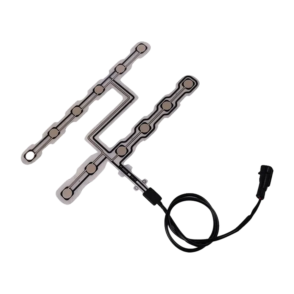
Quick decision: separate dual thresholds from dual channels
| Design question | One channel, two thresholds | Two sensing channels | Engineering implication |
|---|---|---|---|
| Primary purpose | Stabilize assert/release transitions | Add spatial evidence or a second observable response | Do not call the two approaches equivalent |
| Typical output | One analog or conditioned value | Two separately measurable values or states | Specify the electrical interface before drawing the mat |
| Hysteresis | Created by different assert and release limits | Still required for each classified state | Channel count does not prevent threshold chatter |
| Fault information | Limited unless line monitoring is added | Can support correlation checks if channels remain distinguishable | Two printed zones are not automatically independent or redundant |
| Best fit | Clear load path with one stable zone | Seats where distribution across zones matters | Validate the fully trimmed seat, not only a flat fixture |
| Poor fit | Occupant and object responses overlap | Common-mode foam or routing effects dominate both channels | Consider more zones, another modality, or a different system architecture |
“Dual tension” should describe the sensing architecture, not a new OCS class
Dual tension is not a classification defined by FMVSS No. 208, ISO 26262, or IPC. In an engineering drawing or RFQ, replace the shorthand with the actual requirement: one signal with separate assert and release thresholds, two independently readable zones, or two mechanically biased elements that respond at different seat loads. That wording prevents purchasing, electronics, and validation teams from solving three different problems under one label.
Precise language also protects the system boundary. Flexible car seat occupancy sensors can provide contact, resistance, pressure-related, or spatial inputs. The control unit decides how those inputs are filtered, diagnosed, and classified. NHTSA addressed this boundary directly when a sensor-mat supplier asked about certification: FMVSS No. 208 applies to the vehicle, and the vehicle manufacturer is responsible for certifying compliance. Component data may support that work, but it does not transfer the obligation to the mat supplier (NHTSA Interpretation 22492).
For foundational signal-path context, see How Does a Seat Occupancy Sensor Work?. The design decision here begins one level deeper: what observable states must the printed component provide so that the system owner can separate empty, occupied, transition, and fault conditions?
The installed seat stack creates the signal before the electronics see it
A flexible sensor does not receive occupant mass directly. It receives local compression, contact, or deformation after the seat stack has redistributed the load. SAE paper 2005-01-0461 identifies foam stiffness, cover material, preload, seating position, child-restraint geometry, and environmental temperature as relevant variables in a seat-specific resistive OCS mat study. That evidence rules out a universal trigger copied from a flat coupon or a different cushion.
The functional stack usually contains these interfaces, although their order and presence vary by seat:
- Trim and seams transmit tension and can create local preload or hard lines.
- Comfort layers spread the occupant load; sculpted foam and bolsters redirect it.
- Heating, ventilation, or support features introduce openings, stiff regions, and assembly constraints.
- Flexible sensing layer contains active zones, conductors, insulation, adhesive lands, and a tail transition.
- Support structure—foam underside, suspension, springs, or pan—closes the load path and may concentrate reaction force.
- Tail, harness, and connector carry distinguishable electrical states through the seat-motion envelope to the controller.
Occupant / object / child-restraint interface
                    │
                    ▼
          Upholstery, seams, trim tension
                    │
                    ▼
       Foam + heater / ventilation features
                    │ redistributed load
          ┌─────────┴─────────┐
          ▼                   ▼
   Primary sensing zone  Secondary sensing zone
          │ Channel A         │ Channel B
          └─────────┬─────────┘
                    ▼
     Printed conductors → reinforced tail
                    ▼
        Connector / seat harness interface
                    ▼
  Input conditioning → diagnostics → classifier
                    ▼
     Vehicle restraint-system state decision
Zone geometry must therefore follow the repeatable load path of the released cushion. Keep sensing cells and critical conductors away from hog rings, listing wires, trim seams, foam cuts, ventilation holes, sharp support edges, and tail folds unless the design and validation plan explicitly accommodates them. The Automotive HMI Hardware Integration Guide provides related interface-planning context; it is not evidence for OCS thresholds.
Dual thresholds control transitions; dual channels add evidence
A two-threshold state machine uses an upper limit to assert occupancy and a lower limit to release it. If a conditioned signal is (x), the simplest form is:
- enter
OCCUPIEDwhen (x \ge T_{assert}); - remain
OCCUPIEDwhile (x > T_{release}); - return to
EMPTYwhen (x \le T_{release}); - require (T_{release} < T_{assert}).
The interval (T_{assert}-T_{release}) is the system hysteresis band. It prevents normal noise, small posture movement, or viscoelastic recovery from causing repeated state changes at one decision boundary. It does not fix poor mechanical separation. If empty-seat preload and the lightest intended occupied response overlap after tolerance, temperature, aging, and posture are included, widening the band merely moves the error.
Sensor behavior contributes another kind of hysteresis: the electrical response on unloading can differ from the response on loading. An off-the-shelf Tekscan A201 force sensor, for example, lists hysteresis below 4.5% of full scale for a conditioned sensor tested at 80% of full force. That value belongs only to that product and condition; it is evidence that hysteresis needs characterization, not a specification for a custom seat mat. The released design needs its own loading/unloading curves through the complete seat stack.
A dual-channel architecture exposes two responses, such as left/right, rear/front, center/perimeter, or primary/confirmation zones. The classifier can then evaluate absolute values and relationships:
| Observable | What it may reveal | Limitation |
|---|---|---|
| Channel A level | Load in the primary pelvis or seat-center path | Cannot identify the cause of load by itself |
| Channel B level | Secondary thigh, edge, or confirmation loading | May share the same foam and temperature bias as Channel A |
| A + B | Broader load magnitude proxy | Summation can erase useful spatial differences |
| A − B or A:B | Load distribution and off-center posture | Ratio becomes unstable near zero and needs bounded logic |
| Transition timing | Entry, exit, bounce, or intermittent contact | Timing limits are application-specific |
| Plausibility state | Both high, both low, or a defined asymmetric pattern | A plausible pattern is not proof of occupant identity |
NHTSA-sponsored research illustrates why spatial evidence can matter. In a study using a 36 × 36 pressure array, pressure-distribution width, contact area, peak spacing, and summed pressure were evaluated as occupant features. One width feature had an R² of 0.88 for normal posture but 0.38 across all postures, while a summed-pressure feature had R² values of 0.85 and 0.78, respectively. Those are study results, not production thresholds. The useful lesson is that posture changes feature performance, so validation must challenge the decision boundary rather than train it only on nominal seating.
NHTSA has also warned that an occupant system regularly changing airbag status would be problematic. State stability therefore needs both a defined hysteresis band and a defined time policy—filtering, dwell, debounce, or transition handling—owned and validated by the system team (NHTSA Interpretation 003917rbm).
Select sensor zones by the decision that must remain separable
The best architecture is the least complex one that preserves separation across released variants and fault conditions. More channels increase routing, connector, input, calibration, and diagnostic work. Fewer channels reduce observable information. Choose after collecting seat maps, not before.
| Architecture | Choose it when | Required evidence | Main tradeoff | Not suitable when |
|---|---|---|---|---|
| One contact zone | Only a stable open/closed presence input is required | Empty/occupied margin across stack tolerances and conditioning | Lowest circuit and connector complexity | Object and occupant states overlap or a graded signal is required |
| One analog zone with two thresholds | One repeatable load path exists and transition stability is the main problem | Loading/unloading distributions, drift, noise, assert/release margin | Hysteresis is simple to express but adds no spatial information | A second spatial feature is needed to separate target cases |
| Two readable zones | A/B distribution improves classification or fault observability | Each channel's response plus correlation and common-mode analysis | More inputs, traces, terminals, diagnostics, and calibration | Both zones share the same ambiguous load path or cannot remain distinguishable |
| Multi-zone pressure map | Shape and distribution are necessary classifier inputs | Dataset coverage, feature stability, electronics and algorithm evidence | Highest spatial information; greater system complexity | Cost, packaging, data, or validation ownership cannot support it |
| Capacitive or non-seat-based sensing | Pressure patterns remain ambiguous or contact-free detection is required | Modality-specific interference, mounting, classifier, and vehicle evidence | Can add different information rather than more of the same | The vehicle program cannot own the new hardware/software validation scope |
SAE paper 2024-01-2508 describes a capacitive mat that produces spatial capacitance images for an occupancy classifier. It is a useful alternative concept, not proof that capacitive sensing meets a particular vehicle requirement. A flexible printed pressure or contact mat is a poor fit when the required classes overlap under credible posture and object cases, when the cushion cannot maintain a repeatable load path, or when the project expects the component supplier to deliver a complete restraint decision without the controller and vehicle program.
Failure detection must extend through the tail and connector
Two zones improve fault observability only when the electrical interface keeps them distinguishable and the diagnostics can stimulate or interpret them. Splitting one printed node into two shapes but joining both before the connector creates two load areas, not two diagnosable channels. Likewise, two traces sharing a single vulnerable tail neck can fail together.
| Failure path | Possible observation | Design input needed | Validation focus |
|---|---|---|---|
| Open conductor or terminal | Out-of-range line state, no response, or failed continuity check | Bias network, expected open signature, test points | Tail flex, terminal retention, assembly damage, intermittent open |
| Short between channels | A/B values track abnormally or collapse to one state | Channel separation and correlation limits | Moisture/contamination, conductor spacing, connector faults |
| Short to ground or supply | Saturated or implausible input | Controller input protection and diagnostic thresholds | Electrical-load and fault-injection plan |
| Stuck sensing response | State does not change under a defined load sequence | Stimulation sequence and plausibility window | Load/unload cycles in the actual cushion |
| Common-mode preload shift | Both channels move together without occupancy | Empty-seat baseline policy and environmental cases | Trim build, foam lot, temperature, aging, stored objects |
| Intermittent connector or tail | Rapid discontinuity or transition count anomaly | Sampling, debounce, event handling, harness layout | Seat travel, vibration, ingress, service motion |
| Zone swap or wrong assembly | Valid values mapped to the wrong physical location | Keying, orientation marks, channel identification | Poka-yoke, end-of-line check, traceability |
IPC identifies IPC-2223 as the sectional design standard for flexible printed boards, while IPC-6013 addresses qualification and performance for flexible printed boards. These references can govern the printed component when contractually invoked; they do not replace seat-specific mechanical testing. Release the tail outline, conductor necks, stiffener, termination, bend direction, static versus moving regions, strain relief, and test access on the drawing.
Route the connector and service loop outside the seat-track sweep, hinge pinch points, sharp brackets, trim pulls, and occupant-loaded foam cuts. Define whether the tail moves once during assembly or cycles during seat adjustment. Lock connector keying, cavity map, mating interface, retention, sealing requirement, and harness breakout with the system owner. Apply the same scoping discipline to Industrial HMI Standards and Hardware Compliance: a named standard is useful only when its scope, revision, acceptance evidence, and responsible party are explicit.
Vehicle validation remains with the OEM or designated system owner
Component qualification, seat integration, classifier verification, functional-safety evidence, and regulatory compliance are separate gates. NHTSA's TP-208-14 includes suppression-system checks using specified child restraints and child dummies, along with defined seat-position and telltale conditions. NHTSA lists that procedure for FMVSS No. 208, but the regulatory text controls when the two differ. A supplier bench fixture cannot reproduce or replace the applicable vehicle procedure.
ISO 16750-2:2023, ISO 16750-3:2023, and ISO 16750-4:2023 provide scopes for electrical, mechanical, and climatic loads on road-vehicle E/E equipment. Their test selection and severity depend on the mounting location and program. ISO 26262-2:2018 covers functional-safety management, ISO 26262-5:2018 covers hardware development and verification, and ISO 26262-8:2018 covers supporting processes such as distributed-development interfaces, configuration management, change management, and hardware-element evaluation. None supplies a nominal OCS trigger.
Use Seat Occupancy Sensor Testing for OEMs and the site's testing and validation planning resource to organize evidence, while keeping the following ownership split explicit.
| Validation layer | Conditions to cover | Observe and record | Typical decision owner | Exit evidence |
|---|---|---|---|---|
| Printed component | Released materials, zones, trace map, tail, termination | Dimensions, continuity, channel response, workmanship | Sensor supplier per drawing | Inspection and component test records |
| Installed seat | Trim/foam variants, build tolerances, track positions, posture, entry/exit, objects | A/B distributions, assert/release margin, transitions, false states | Seat/Tier 1 system team | Approved seat-level dataset and boundary analysis |
| Environmental/mechanical | Program-defined electrical, mechanical, climatic, and life conditioning | Drift, intermittency, damage, recovery, diagnostic response | OEM/Tier 1 with supplier inputs | Qualified configuration and test reports |
| Diagnostic/fault injection | Open, short, cross-channel, stuck, swapped, intermittent cases | Detection, reaction, latency, recovery, stored status as specified | ECU and functional-safety owner | Requirements trace and verification results |
| Vehicle classification | Applicable occupants, child restraints, objects, seat positions, state transitions | Final class/state and stability | OEM or designated OCS owner | Vehicle integration and classifier validation |
| Regulatory/homologation | Applicable FMVSS No. 208 compliance option and official conditions | Required system and telltale behavior | Vehicle manufacturer | Certification evidence and controlled records |
Freeze thresholds only after distributions—not just averages—are available for every released seat stack. Review channel overlap, guard bands, worst-case transitions, and failure reactions. A late foam, trim, heater, ventilation, adhesive, connector, tail-route, or software-filter change can invalidate the evidence and must trigger a documented impact assessment.
Release the drawing and sample plan together
The RFQ should define enough of the seat and electrical boundary for a supplier to build the intended component without inventing system behavior. Provide:
- seat position, cushion plan and sections, trim construction, foam variants, support features, heating or ventilation layers;
- primary and secondary sensing zones, forbidden areas, installation datum, orientation, and expected load paths;
- channel function, output concept, measurement circuit assumptions, assert/release ownership, and diagnostic states;
- mat outline, materials, active geometry, spacer or adhesive pattern, trace map, tail exit, reinforcement, cable length, connector and pinout;
- occupied, empty, posture, edge-load, object, transition, temperature, conditioning, and fault cases supplied by the system owner;
- component acceptance method, seat-level fixture, sampling, traceability, change control, and responsibility matrix;
- prototype quantities, build stages, sample-identification scheme, data format, and release criteria.
Use prototyping and sample approval to separate an early geometry sample from an electrically characterized seat sample and a release-candidate build. Before the final CTA, send drawings for engineering review with the seat stack, sensing zones, threshold logic boundary, tail routing, connector interface, and named validation owner.
Frequently asked questions
What does dual tension mean in a seat occupancy sensor?
Dual tension is project shorthand, not a standardized OCS term. It should be translated into a measurable requirement: two assert/release thresholds on one signal, two separately readable sensing zones, or two mechanically biased elements with different response ranges. The drawing must state which interpretation applies and who owns the downstream classification logic.
Is a dual-threshold sensor the same as a dual-channel sensor?
No. A dual-threshold design uses one measured channel and different limits for entering and leaving a state. A dual-channel design provides two measurable responses, often from different seat zones. Two channels can support spatial or plausibility checks, but each channel still needs its own thresholds, filtering, and fault strategy.
How much hysteresis should an OCS sensor input use?
There is no universal hysteresis value. Set the assert and release limits from installed-seat loading and unloading distributions across tolerance, posture, temperature, conditioning, noise, and aging. The band must prevent unstable transitions without hiding real exits. The OEM or system owner must validate the final thresholds, dwell policy, and state reaction.
Can two sensing zones distinguish a person from an object?
Two zones can add load-distribution evidence, but they cannot guarantee person-versus-object classification. Bags, child restraints, off-center occupants, clothing, and seat geometry can produce overlapping patterns. The classifier must be validated with program-defined occupant and object cases; if separation remains inadequate, use more spatial information or another sensing modality.
Where should the primary and secondary zones be placed?
Place them where the fully trimmed seat produces repeatable, distinguishable load paths for the target cases. Review pressure maps and seat sections across posture and build variation. Avoid seams, bolsters, hard edges, ventilation holes, attachment hardware, and tail-stress areas unless the design explicitly uses and validates those features.
What faults should a dual-channel seat sensor detect?
The system safety analysis should consider open conductors, shorts to ground or supply, channel-to-channel shorts, stuck responses, swapped channels, intermittent tail or connector faults, and common-mode preload shifts. Detection depends on the measurement circuit and architecture. Two printed zones do not provide diagnostic independence unless the interface preserves distinguishable fault signatures.
Does a component test report prove FMVSS No. 208 compliance?
No. NHTSA states that FMVSS No. 208 applies to the vehicle and that the vehicle manufacturer certifies compliance. Component reports can support due-care evidence for a released mat, but they do not replace installed-seat classification, restraint-system integration, applicable NHTSA test conditions, or vehicle certification.
What should an OEM send with a dual-channel sensor RFQ?
Send the seat stack and sections, sensing-zone map, forbidden areas, load-path evidence, signal concept, channel and diagnostic definitions, assert/release ownership, tail and connector route, environmental and fault cases, component acceptance method, prototype stages, change-control rules, and the organization responsible for seat, classifier, vehicle, and regulatory validation.
Move from seat evidence to a controlled component release
A useful engineering handoff contains the seat stack, sensing zones, threshold-logic boundary, tail routing, connector definition, fault expectations, and validation ownership in one package. JASPER can review the flexible printed component and manufacturing drawing while the OEM or designated system owner retains the classifier, restraint decision, safety lifecycle, and vehicle certification. When those inputs are ready, request an engineering quote.
References
- National Highway Traffic Safety Administration. Interpretation 22492: FMVSS No. 208 responsibility for an occupant-classification sensor mat. 2001.
- National Highway Traffic Safety Administration. Laboratory Test Procedure TP-208-14, Occupant Crash Protection. April 16, 2008.
- National Highway Traffic Safety Administration. Advanced Air Bag Rule, 65 FR 30680. May 12, 2000.
- National Highway Traffic Safety Administration. Interpretation 003917rbm: suppression-state telltale and transition behavior. 2003.
- Reed, M. P., et al. Development of Performance Specifications for the Occupant Classification Anthropomorphic Test Device. 17th International Technical Conference on the Enhanced Safety of Vehicles, 2001.
- Scholpp, G., Weber, A., Dias, H. C., and Scherf, O. CAE Application for the Layout of an Occupant Classification Sensor Mat. SAE Technical Paper 2005-01-0461, April 11, 2005.
- Prasanna Kumar, R., Melcher, D., Buttolo, P., and Jia, Y. Vehicle Seat Occupancy Detection and Classification Using Capacitive Sensing. SAE Technical Paper 2024-01-2508, April 9, 2024.
- International Organization for Standardization. ISO 16750-2:2023, electrical loads; ISO 16750-3:2023, mechanical loads; ISO 16750-4:2023, climatic loads. July 2023.
- International Organization for Standardization. ISO 26262-2:2018, functional-safety management; ISO 26262-5:2018, hardware-level development; ISO 26262-8:2018, supporting processes. December 2018.
- IPC International. IPC Board Design Standards and IPC Document Revision Table. Accessed August 24, 2026.
- Tekscan. FlexiForce A201 Sensor Specifications. Accessed August 24, 2026; supplier values are cited only under the stated test conditions.
JASPER manufactures custom flexible printed sensor components. Regulatory compliance, occupant classification, diagnostics and vehicle validation must be addressed at the seat and vehicle system level.
Bring the drawing, stack and operating conditions
JASPER engineering will review the interfaces, open risks and evidence required for a production quote.