
Seat occupancy sensor testing demonstrates that each defined seat state remains correct across component variation, the installed cushion stack, environmental exposure, repeated loading, connector movement, electronics, and credible faults. The OEM program sets the acceptance boundaries and owns final vehicle validation.
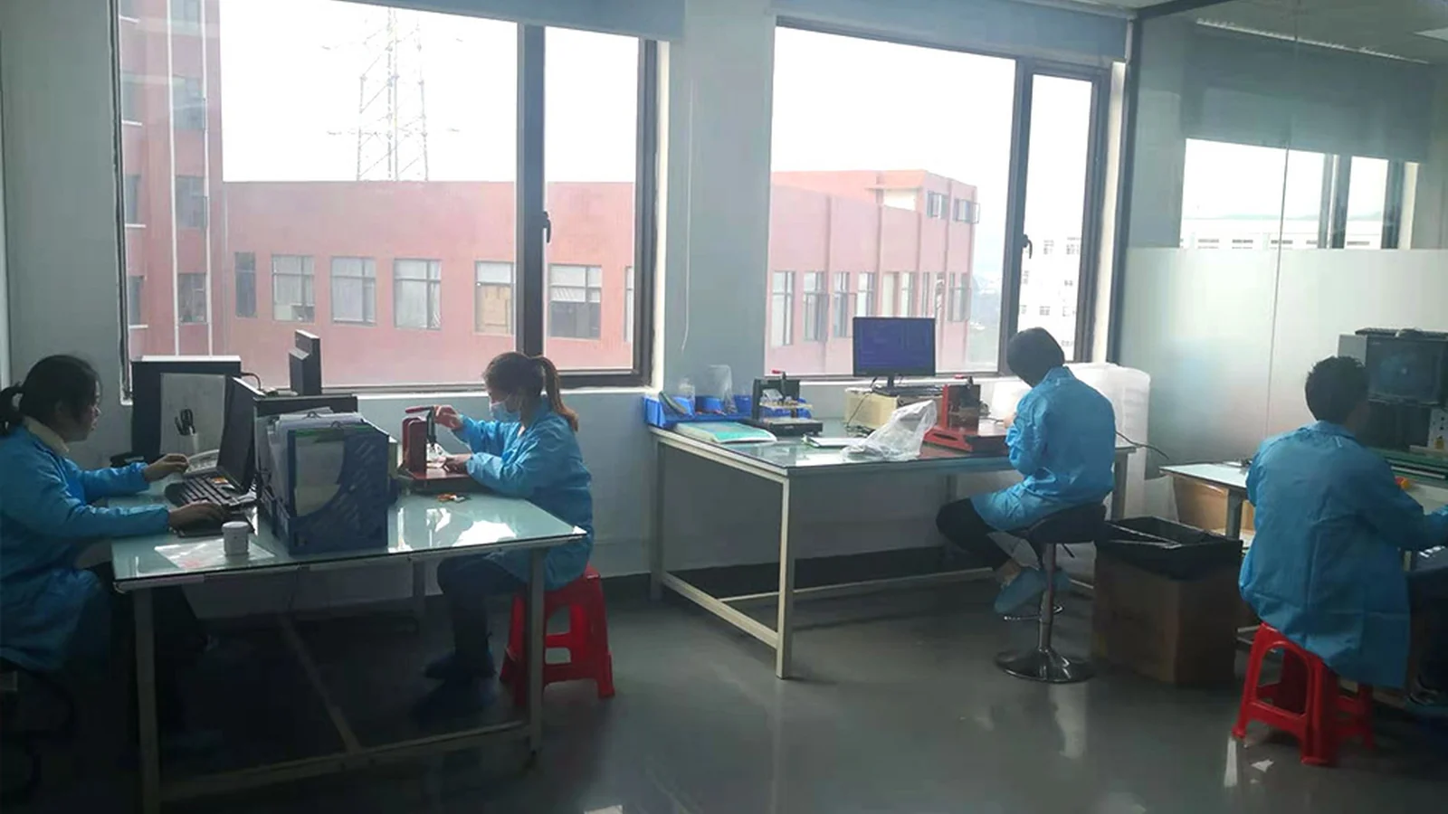
JASPER certifications: ISO 9001, ISO 13485, IATF 16949, and ISO 14001.
For an OEM or Tier 1 team, the decision is not simply whether a mat changes continuity under one central load. A useful plan decides which empty, occupied, transitional, and fault states must be recognized; under which seat builds and operating conditions; and which evidence belongs to the sensor supplier, seat integrator, controller team, or vehicle manufacturer. This guide provides that matrix. It does not assign universal trigger weights, cycle counts, environmental severities, or vehicle-compliance results.
JASPER reviews custom seat occupancy sensor options against the project drawing, seat stack, circuit, connector and validation requirements.
What Seat Occupancy Sensor Testing Must Prove
A complete plan proves a decision chain, not merely a sensing element. The chain starts with a person, test body, object, or defined non-activation case. Seat trim, foam, support structures, fasteners, adhesive, and assembly preload then distribute that input before it reaches the sensor. Electronics convert the raw output into a stable state; software applies thresholds, timing, fault handling, and system logic. Only the final vehicle can produce the warning, restraint, comfort, or monitoring action.
Occupant, object, or specified test input
Trim + foam + support + assembly preload
Sensor zones + tail + connector
Excitation / continuity circuit / ADC
Thresholds + hysteresis + timing + diagnostics
Empty / occupied / transitional / fault state
Vehicle warning, restraint, comfort, or control action
This stack creates four evidence levels:
| Validation level | Question answered | Typical evidence | Primary owner |
|---|---|---|---|
| Sensor component | Does the released part match its drawing and electrical map? | Identity, dimensions, visual criteria, continuity/open/short, zone-to-pin map, raw response | Sensor supplier against approved customer criteria |
| Installed seat | Does the real load path create repeatable activation and release? | Seat-build matrix, load positions, preload, dwell, recovery, assembly variation | Seat integrator with sensor supplier support |
| Controller/interface | Does the electrical chain classify valid, transitional, and fault inputs correctly? | Circuit configuration, raw data, thresholds, timing, fault injection, diagnostic response | Electronics and system team |
| Vehicle/system | Does the finished function meet program and legal requirements? | Vehicle-state tests, safety validation, regulatory records, change control | OEM or legally responsible vehicle manufacturer |
Each level has limits.
NHTSA's laboratory procedure for FMVSS No. 208 occupant crash protection addresses vehicle-level requirements ; its procedure may not include every minimum requirement or guarantee certification. UNECE now publishes safety-belt-reminder vehicle requirements as UN Regulation No. 174. Neither source turns a bare sensor continuity result into a vehicle approval.
The distinction matters during sourcing. A supplier can demonstrate that a component conforms to an approved drawing and agreed component test. It cannot silently inherit ownership of seat mechanics, ECU calibration, system diagnostics, functional-safety validation, or the final regulatory decision. JASPER's public product scope makes the same boundary explicit: the sensor is an input to a larger seat and vehicle system, and the OEM or Tier 1 team retains the integration and compliance work.
Seat Sensor Validation Starts with Acceptance States
Seat sensor validation should begin with a state table. Test methods come second. If “occupied” is not defined at the controller interface, a laboratory can produce precise force and resistance data without answering the system question.
At minimum, the program should define these states:
| State | Required definition | Boundary cases to include | Evidence retained |
|---|---|---|---|
| Empty | Approved raw-output band and final controller state for an unloaded, assembled seat | Foam/trim preload, seat position, build variation, recovery after unloading | Raw signal, controller state, timestamp, seat and sensor revision |
| Occupied | Approved raw-output band and final state for every required load/posture case | Zone edges, off-center positions, posture and assembly extremes | Applied input, contact geometry, location, raw signal, state and timing |
| Transitional | Allowed behavior while load, position, or signal crosses a decision boundary | Movement between zones, bounce, analog noise, slow loading and unloading | Time series, candidate state, filtering and debounce behavior |
| Fault | Electrical or logical condition that must not be accepted as a normal state | Open line, shorted lines, disconnected connector, stuck contact, out-of-range analog value | Injected fault, diagnostic, fallback state, detection and recovery time |
Activation and release need separate limits. A contact mat may close under one load path but release only after the foam, spacer, adhesive, or contact structure recovers. An analog device may follow different loading and unloading curves. The specification should therefore identify the measured quantity, input direction, stable-state rule, allowed timing, and reset or recovery condition. “Passes at the threshold” is incomplete when it does not say whether the sample was being loaded or unloaded.
Loading direction changes the answer.
Hysteresis and debounce solve different problems. Hysteresis uses different rising and falling boundaries; debounce requires a candidate state to remain valid for a specified duration or sample count. Both can suppress chatter near a boundary. Neither can create physical separation when approved empty and occupied cases share the same steady-state signal range. That overlap calls for a change to the load path, sensing zones, circuit, calibration data, or architecture—not a more flattering chart.
Verify the fixture before accepting or rejecting the sensor
The measurement chain must be capable of resolving the intended decision. Record the actuator geometry, contact area, alignment, loading direction, rate, dwell, support condition, reference force or displacement, electrical circuit, sample rate, filtering, fixture revision, instrument calibration status, operator, and ambient condition.
The NIST Gauge R&R framework treats repeatability, reproducibility, stability, bias, resolution, linearity, hysteresis, drift, operators, gauges, and configurations as separate measurement-system questions. The AIAG Measurement Systems Analysis manual supplies the automotive-industry context. Neither source supplies a universal pass percentage for this sensor; the program must choose a study that matches the data type, range, risk, and customer requirement.
The failure chain is simple enough to draw and expensive enough to ignore:
Seat-build or test-fixture variation
Different force reaches the active zone
Raw contact or analog output shifts
Signal crosses the wrong boundary—or never crosses
False occupied / missed occupied / chatter / late release / fault
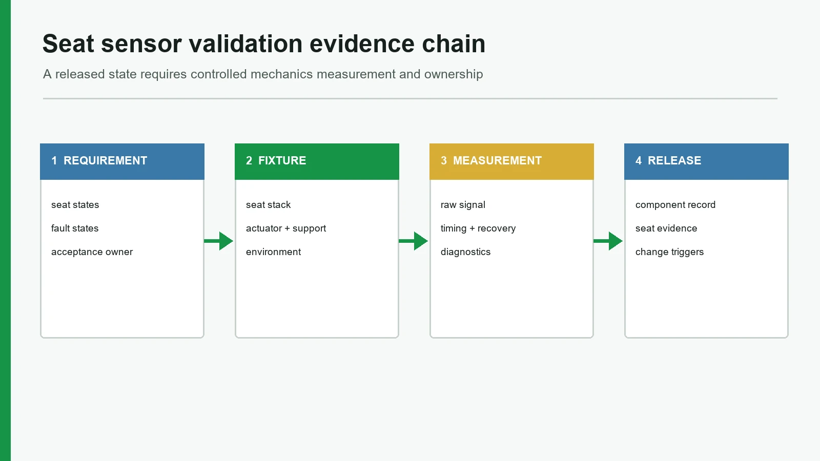
A closed section should leave four artifacts: an approved state table, a controlled measurement method, time-resolved raw data, and an acceptance rule that names the owner. A pass/fail cell without those artifacts is not validation evidence; it is a color.
The OEM Seat Occupancy Sensor Testing Matrix
An OEM seat occupancy sensor testing matrix should connect each requirement to a failure mode, a controlled setup, a recorded output, an acceptance boundary, and an evidence owner. Test names alone are too vague. “Cycle,” for example, could mean pressing one bare zone, loading the complete cushion, flexing a tail, mating a connector, or running a controller state machine.
The label is not enough.
The matrix defines the evidence fields; every acceptance value must come from the released drawing, DVP&R, customer specification, approved engineering study, or controlled reference. JASPER's public testing and validation planning follows the same drawing-and-risk principle; the actual JASPER test scope remains project-specific and must be confirmed.
Build acceptance rules around distributions, not one convenient sample
For activation and release, collect raw distributions for the approved empty cases, occupied cases, seat builds, positions, directions, environmental states, and recovery states. Boundary samples should represent credible design and process limits. A pristine “golden sample” helps with fixture checks but cannot stand in for production variation.
Public patents illustrate two useful structures without creating industry requirements. Audi's EP3812737A1 describes a functional test that combines force and position with an automated test body. Rivian's United States Patent 11,644,377 describes environment-related upper and lower acceptance boundaries. These are non-normative examples. An OEM may use another actuator, statistic, corridor, model, or decision rule.
Freeze the tested configuration
Each result should identify the sensor part and revision; manufacturing lot; seat frame, support, foam, trim, cover and adhesive revisions; installation orientation; tail route; connector; controller hardware and software; circuit; fixture; calibration state; operator; test date; and deviations. If any of these changes after the test, the change review should decide whether the result still applies.
Do not merge supplier validation and customer validation into one ambiguous “approved” column. The supplier can close component drawing and agreed component-test requirements. The customer or designated system owner closes installed-seat acceptance, ECU logic, diagnostics, vehicle performance, and legal evidence. That division should appear in the DVP&R before samples arrive.
How to Define an Occupancy Mat Life Test
An occupancy mat life test is complete only when it defines the mechanical input, seat stack, electrical state, sequence, checkpoints, functional limits, and failure evidence. A cycle target on its own says almost nothing. Ten laboratories could run the same nominal count with different contact areas, peaks, rates, dwell times, foam builds, seat supports, temperatures, circuits, and inspection intervals—and produce ten different stresses.
Separate three mechanisms before selecting methods:
- Sensor durability — printed conductors, contacts, spacers, force-sensitive material, laminations, tail transitions, and adhesive interfaces can change under repeated loading.
- Seat-stack recovery — foam, trim, upholstery tension, support ribs, and assembly preload can change the force transferred to the sensing zones.
- Connection-system durability — the tail, terminal, connector, strain relief, and routed harness can fail independently of the active mat.
The test should measure function through the sequence, not only after it:
Sequence changes the stress.
Baseline characterization
Preconditioning, if specified
Repeated load / unload with controlled dwell and position
Interval checks of activation, release, drift and intermittency
Environmental exposure or combined loading, if required
Immediate post-exposure measurement
Defined recovery period
Final functional test + physical inspection + failure analysis
Compression set belongs to the material and load-path discussion
Compression set should not be used as a loose synonym for sensor life. ISO 1856:2018 specifies compression-set methods for flexible latex and polyurethane foams thicker than 2 mm. ISO 3385:2014 addresses thickness and hardness loss in load-bearing flexible cellular upholstery under constant-load pounding, while warning that measured losses are not necessarily identical to service losses.
Those standards can support a cushion-material plan when their scope fits. They do not set the electrical acceptance of a printed sensor mat. A strong program records foam thickness or hardness change separately from sensor activation, release, raw-output drift, and recovery. If the seat no longer transfers load the same way, the sensor may appear to have drifted even when its bare-component response is unchanged. The installed-seat result still fails if the final state misses its requirement; the failure analysis must identify which layer moved.
Environmental standards are method families, not prefilled severities
| Source | Public scope that can be used | What the project must still define |
|---|---|---|
| IEC 60068-1:2013 | General environmental-test guidance and tailoring | Applicable stresses, severities, sequence, operating state and pass criteria |
| IEC 60068-2-14:2023 | Change-of-temperature tests | Temperatures, transfer profile, dwell, powered state, measurement timing and limits |
| IEC 60068-2-78:2025 | Steady-state high humidity without condensation | Temperature, humidity, duration, preconditioning, recovery and functional limits |
| ISO 16750-3:2023 | Mechanical loads for road-vehicle E/E equipment at relevant locations | Applicability to the article, mounting, axes, operating mode, severity and monitoring |
| ISO 16750-4:2023 | Climatic loads for road-vehicle E/E equipment | Vehicle location, profile, sequence, state and acceptance evidence |
| ISO 20653:2023 | Road-vehicle enclosure protection against foreign objects, water and access | The enclosure boundary, required IP code and a test report; a flexible mat is not automatically an enclosure |
Measure before exposure, during exposure where required, immediately afterward, and after a defined recovery. A final continuity check can miss temporary drift, moisture-dependent chatter, slow release, or a fault that disappears after the chamber door opens. Combined sequences also deserve attention: humidity followed by flexing, temperature change under preload, or cycling followed by connector disturbance may expose a different failure than isolated tests.
Validate the tail and connector as a connection system
The current public scope of SAE/USCAR-2 Revision 9 covers performance testing for low-voltage road-vehicle terminal and connector systems through development, production, and field analysis. That is a separate boundary from mat continuity.
Routing matters. A 2025 USCAR-2 change letter revised a sealing setup because an unbent harness did not represent side loads applied by taped and routed bundles. The lesson is broader than sealing: validate the connector in its intended mated state, harness dress, bend direction, strain relief, support, and disturbance condition. Never infer a complete connector qualification from a stable meter reading on an unstressed bench sample.
Passenger Sensor Acceptance Test: Qualification, Periodic and EOL Gates
A passenger sensor acceptance test needs a named gate. Design qualification, periodic verification, production end-of-line testing, and vehicle validation answer different questions. Reusing one fixture and one pass limit across all four can either miss risk or burden production with tests that do not belong there.
Gate names control scope.
| Gate | Decision | Appropriate evidence | Tests that usually do not belong here | Release authority |
|---|---|---|---|---|
| Design qualification | Does the released design meet requirements across the defined variation space? | Boundary seat builds, activation/release distributions, environment, durability, connector, fault injection, failure analysis | A single golden-sample check | DVP&R owner / OEM or Tier 1 program |
| Periodic or change-based verification | Does the process or changed design still match the qualified state? | Targeted checks tied to risk, drift, supplier/process changes, audits and defined intervals | Repeating every destructive qualification sequence without a risk reason | Customer and supplier quality under the control plan |
| Production EOL or in-process control | Was this component or assembled seat built and connected correctly? | Identity, visual/dimensional criticals, continuity/open/short, pin/zone map, rapid functional points, diagnostics where integrated | Long environmental exposures, full life cycling, destructive material tests | Manufacturing quality under an approved reaction plan |
| Vehicle/system validation | Does the complete vehicle function satisfy the program, safety concept and applicable law? | Installed states, warnings/actions, diagnostics, software, vehicle conditions and regulatory records | Treating a supplier component report as the final vehicle result | OEM or legally responsible manufacturer |
EOL limits should trace back to qualified design evidence. A rapid component screen can protect the critical characteristics shown during development, but it should not claim more coverage than it has. The test record should preserve part identity, revision, fixture status, measured values, failure code, rework, retest, and reaction-plan outcome—not merely a green lamp.
Choose sample size from the decision and risk
There is no defensible universal “three pieces” or “thirty pieces” rule. A calculation depends on the hypothesis, alpha risk, beta risk, detectable difference, and process variation. Reliability demonstrations also need an assumed model and a defined failure criterion. The sample plan should state what it is trying to detect or demonstrate, which variants are represented, how failures are treated, and which confidence or risk target applies.
Official field actions show three different failure layers
| Public NHTSA record | Documented layer | Validation lesson—not a universal test value |
|---|---|---|
| BMW recall 08V-384 | Mechanical fatigue/cracking of an occupant-detection mat under external force | Include realistic load paths, bending and fatigue; investigate the physical failure mode. |
| Toyota Prius V recall 15V-013 / F0C | Manufacturing calibration error | Treat zero-point or sensitivity checks as controlled production/calibration evidence when the architecture requires them. |
| Zeekr recall 25V-067 | Occupant-weight-sensor software behavior | Test the complete signal chain, diagnostics and software response; continuity alone cannot cover classification logic. |
These records do not provide a transferable cycle count, switch point, or EOL limit. They show why a validation plan must connect mechanical construction, calibration, software, diagnostics, and vehicle action.
Keep regulatory conditions at vehicle level
The latest United States timing matters for program plans. 91 FR 17144 sets September 1, 2028 as the mandatory compliance date for both the updated front and rear seat-belt-warning requirements. The rear-seat rule permits more than one compliance approach and does not universally require a pressure mat. Likewise, UN R174 includes vehicle-level test conditions; a mass used in a regulatory procedure is not automatically the sensor's electrical activation threshold.
The system owner must translate the applicable vehicle requirement into component, seat, controller, and diagnostic requirements. A supplier should never paste a regulatory test mass into a drawing and call the component validated.
When a Pressure or Contact Mat Is Not the Best Choice
A pressure or contact mat is not the best architecture when the required decision exceeds what the seat load path and raw signal can separate. The architecture should follow the function, not the component already on the sourcing list.
The physics decides.
| Required function or constraint | Why a simple mat may be insufficient | Architecture question to reopen |
|---|---|---|
| Absolute load or calibrated mass | A binary contact or relative-resistance output is not an absolute force measurement | Does the seat need structural load sensing, calibrated transducers, or another traceable measurement path? |
| Human-versus-object or detailed occupant classification | Similar seat loads can produce overlapping pressure responses | Should the system use higher-resolution pressure zones, capacitive sensing, camera/radar sensing, or sensor fusion? |
| Large seat-build variation with overlapping states | Filtering cannot separate steady-state distributions that physically overlap | Can the foam/support geometry, sensor location, active area, circuit, or sensing principle change? |
| No stable load path | A mat cannot measure a force that trim, suspension, gaps, ribs, or posture do not transfer consistently | Should the sensor move to a structural point or use a non-contact method? |
| Safety concept requires richer diagnostics or redundancy | A passive element may not provide the diagnostic coverage allocated by the system design | What hardware, software, monitoring, redundancy, and fallback does the ISO 26262 process allocate? |
SAE's 2024 paper on capacitive seat-occupancy detection and classification is one published example of an alternative sensing approach; it is not proof that capacitive sensing fits every seat. ISO 26262-4:2018 places integration, testing, and safety validation at the system level and explicitly separates functional safety from nominal performance. The system architecture must satisfy both.
Project Inputs and Sample Approval Checklist
A validation program should not start until the tested article, applied input, measured output, and release authority are identifiable. Freeze the following inputs before a prototype becomes the reference sample.
Function and interface
- Required empty, occupied, transitional, startup, unknown, and fault states
- Raw output type: contact, resistance, voltage, capacitance, digital message, or other defined signal
- Measurement or excitation circuit, ADC/reference, sampling, filtering, hysteresis, debounce, timing, diagnostics, and fallback
- Required sensing zones, non-sensing areas, load positions, postures, objects, and misuse cases
Mechanical stack and connection
- Seat frame/support, foam, trim, cover, seams, ribs, cutouts, suspension and seat adjustment range
- Sensor outline, active-zone coordinates, adhesive/mounting method, orientation, allowable placement variation and assembly preload
- Tail exit, bend restrictions, strain relief, connector, mating half, pinout, harness route and service handling
- Controlled drawings and revision identifiers for every test article
Test and acceptance
- Requirement-to-failure-mode matrix and named test level
- Fixture/contact geometry, coordinate system, reference load/displacement method, rate, dwell, recovery and sequence
- Environmental method, edition, severity, powered/unpowered state, mechanical load during exposure and measurement timing
- Sample rationale, variants/lots, repetitions, statistical objective and failure handling
- Raw-data fields, acceptance boundaries, report template, retained evidence, deviation process and revalidation triggers
- Supplier, seat integrator, electronics, system-safety, manufacturing and OEM approval responsibilities
For JASPER projects, the seat occupancy sensor mat construction and the seat stack should be reviewed together. A drawing can then define what the component supplier can verify and what remains for the customer system. The actual equipment, sample plan, test location, report format, and acceptance limits must be agreed before sample approval.
Frequently Asked Questions
What should seat occupancy sensor testing include?
Seat occupancy sensor testing should cover part identity, dimensions, visual condition, continuity/open/short, zone mapping, activation, release, timing, installed-seat load positions, environmental response, repeated loading, recovery, tail/connector behavior, fault injection, and production controls. Each test needs a defined article, setup, raw measurement, acceptance rule, owner, and retained record.
Is continuity testing enough for a seat occupancy sensor?
No. Continuity can confirm a circuit state, pin map, open trace, or unintended short under the tested condition. It does not prove activation or release boundaries, seat-zone coverage, analog calibration, environmental stability, life performance, diagnostic behavior, or the final vehicle state. It belongs in the plan, but it is only one row.
Should the sensor be tested inside the real seat?
Yes, when the requirement depends on the installed load path. Bare-component tests are useful for drawing conformance and controlled comparison. Installed-seat tests capture foam, trim, support, preload, sensor placement, adhesive, seat adjustment, tail routing, and assembly variation. Both levels are needed when those factors can move the system decision.
How many cycles should an occupancy mat life test use?
There is no universal cycle count. The OEM or system owner should derive the target from the service profile, program requirement, failure mechanism, load geometry, rate, dwell, seat stack, environment, sample plan, and reliability objective. The acceptance rule should also require functional checkpoints, final recovery measurements, inspection, and failure analysis—not merely completion of the counter.
What belongs in a passenger sensor acceptance test?
The test should name its gate—design qualification, periodic verification, EOL, or vehicle validation—then define the test article, seat build, fixture, input, location, circuit, software, raw-output fields, state and timing limits, sample rationale, failure handling, evidence owner, and release authority. A generic pass/fail result without those fields is not transferable.
How many samples are needed for seat sensor validation?
Sample size depends on the decision, variants, expected variation, detectable difference, failure model, and accepted alpha and beta risks. NIST guidance does not provide one universal number without assumptions. The plan should document its statistical or risk-based rationale and include credible design and process boundaries.
Do ISO 16750 or IEC 60068 set universal seat sensor pass limits?
No. ISO 16750 organizes road-vehicle environmental loads, while IEC 60068 provides general guidance and methods for specific exposures. The project still has to select the applicable part and edition, mounting condition, severity, sequence, operating state, recovery, sample plan, measured characteristic, and acceptance rule. A standard name alone is not a test specification.
Can a component report prove FMVSS No. 208 or UN R174 compliance?
No. FMVSS No. 208 and UN Regulation No. 174 govern vehicle/system outcomes in their applicable jurisdictions and scopes. A component report can support the evidence chain, but the OEM or legally responsible manufacturer must integrate the seat, electronics, diagnostics, software, and vehicle tests and retain the final compliance records.
Build a Project-Specific Validation Plan
Start with the state table and responsibility stack, then complete the validation matrix before samples are approved. The fastest useful input package contains the seat cross-section, sensor drawing, active-zone coordinates, load cases, circuit, connector and harness details, environmental profile, life target, software/diagnostic assumptions, sample rationale, acceptance rules, and report format.
Use drawing-based seat-sensor review to define equipment, evidence ownership, test location, and the project-specific validation plan.
Technical References
- Source: NIST Gauge R&R framework. Accessed 2026.
- Source: ISO 16750 road-vehicle environmental conditions. Accessed 2026.
- Source: IEC 60068 environmental testing methods. Accessed 2026.
- Source: SAE USCAR-2 automotive connector-system testing. Accessed 2026.
- Source: NHTSA FMVSS No. 208 laboratory procedure. Accessed 2026.
- Source: FMVSS No. 208 occupant crash protection. Accessed 2026.
- Source: UN Regulation No. 174. Accessed 2026.
- Source: AIAG Measurement Systems Analysis manual. Accessed 2026.
- Source: EP3812737A1. Accessed 2026.
- Source: United States Patent 11,644,377. Accessed 2026.
- Source: ISO 1856:2018. Accessed 2026.
- Source: ISO 3385:2014. Accessed 2026.
- Source: IEC 60068-1:2013. Accessed 2026.
- Source: IEC 60068-2-14:2023. Accessed 2026.
- Source: IEC 60068-2-78:2025. Accessed 2026.
- Source: ISO 16750-3:2023. Accessed 2026.
- Source: ISO 16750-4:2023. Accessed 2026.
- Source: ISO 20653:2023. Accessed 2026.
- Source: SAE/USCAR-2 Revision 9. Accessed 2026.
- Source: USCAR-2 change letter. Accessed 2026.
- Source: NIST sample-size guidance. Accessed 2026.
- Source: NIST acceptance-sampling handbook. Accessed 2026.
- Source: BMW recall 08V-384. Accessed 2026.
- Source: Toyota Prius V recall 15V-013 / F0C. Accessed 2026.
- Source: Zeekr recall 25V-067. Accessed 2026.
- Source: 91 FR 17144. Accessed 2026.
- Source: capacitive seat-occupancy detection and classification. Accessed 2026.
- Source: ISO 26262-4:2018. Accessed 2026.
Build the validation plan around the released seat
Send the seat stack, required states, fixture, circuit, environmental profile, faults, samples, and acceptance evidence.