
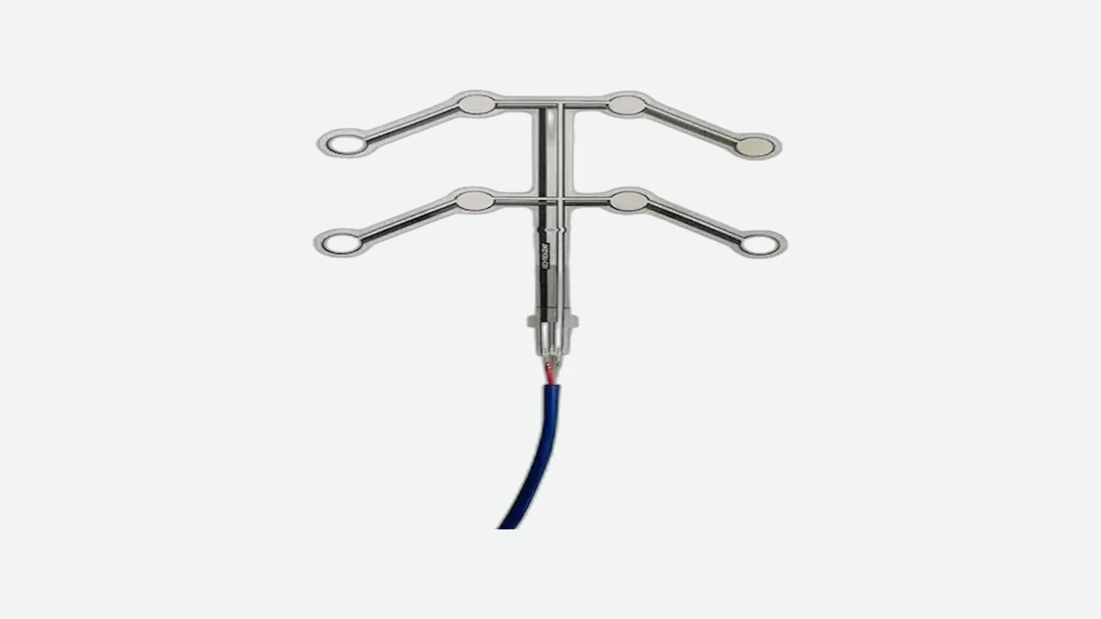
A seat occupancy sensor is a seat-integrated sensing element whose electrical response changes when the seat load path is disturbed; controller logic then converts that response into an empty, occupied, transitional, unknown, or fault state.
JASPER certifications: ISO 9001, ISO 13485, IATF 16949, and ISO 14001.
How does a seat occupancy sensor work? The seat cover and foam transfer an occupant’s load to a pressure mat, force-sensing resistor (FSR), or another sensing element. Electronics read the resulting contact, resistance, voltage, or multi-zone pattern, reject implausible inputs, and apply thresholds plus time rules before reporting an occupancy state. This article helps seat, electronics, and validation teams choose the sensing principle and define the interface. It does not provide repair or bypass instructions, a universal trigger weight, or a vehicle-level restraint calibration. Those decisions depend on the installed seat, controller, safety concept, and target-market requirements.
What a Seat Occupancy Sensor Detects—and What It Does Not
A seat occupancy sensor detects a physical or electrical change associated with load in a seat. The name describes the sensor’s system role, not one universal construction. A pressure mat occupancy sensor may close contacts at several zones. An FSR may produce a continuous resistance change. A capacitive passenger presence sensor may respond to an electric-field change instead of load. Cameras and cabin radar can observe the occupant without placing the sensing element in the cushion.
That distinction prevents an expensive specification error: a sensing element does not make the final safety decision by itself. It provides an input. The vehicle or seat controller owns signal conditioning, state logic, diagnostics, communication, and the downstream action.
For projects that have already defined the required seat state and physical envelope, view custom seat occupancy sensor options for JASPER’s pressure-mat and FSR component scope. The product page is a sourcing route; it is not evidence that one construction fits every seat or function.
The installed seat stack is part of the measurement
A typical seat-integrated pressure sensor sits somewhere in the load path between the occupant and a supporting structure. Public patent literature describes pressure-sensing devices between trim and foam and distributes sensing elements across the seating surface, while IEE publishes examples of both A-surface and B-surface integration for foil-based sensing mats. These examples show possible architectures, not a universal production stack. EPO EP 1531093 A1 and IEE’s vehicle occupant sensing factsheet document the respective arrangements.
Representative load stack, top to bottom:
Occupant or object
▼
Seat trim / upholstery · tension and seams redistribute load
▼
Comfort foam · thickness, stiffness, contour, and aging matter
▼
Heater or ventilation layer, if present · may bridge or redirect force
▼
Protective film / adhesive carrier · changes local stiffness and preload
▼
Pressure mat or FSR zones · contact or resistance responds
▼
Support foam / felt / seat pan · defines the reaction surface
Sensor tail → strain relief → connector → seat ECU or vehicle controller
The foam is not passive packaging. It spreads a concentrated load, creates preload, and changes recovery after the occupant leaves. Trim tension, heater geometry, cushion grooves, and the support surface can move the sensor’s empty and occupied distributions. A bare-element bench press therefore answers only whether the element responds. It does not prove installed seat occupancy detection.
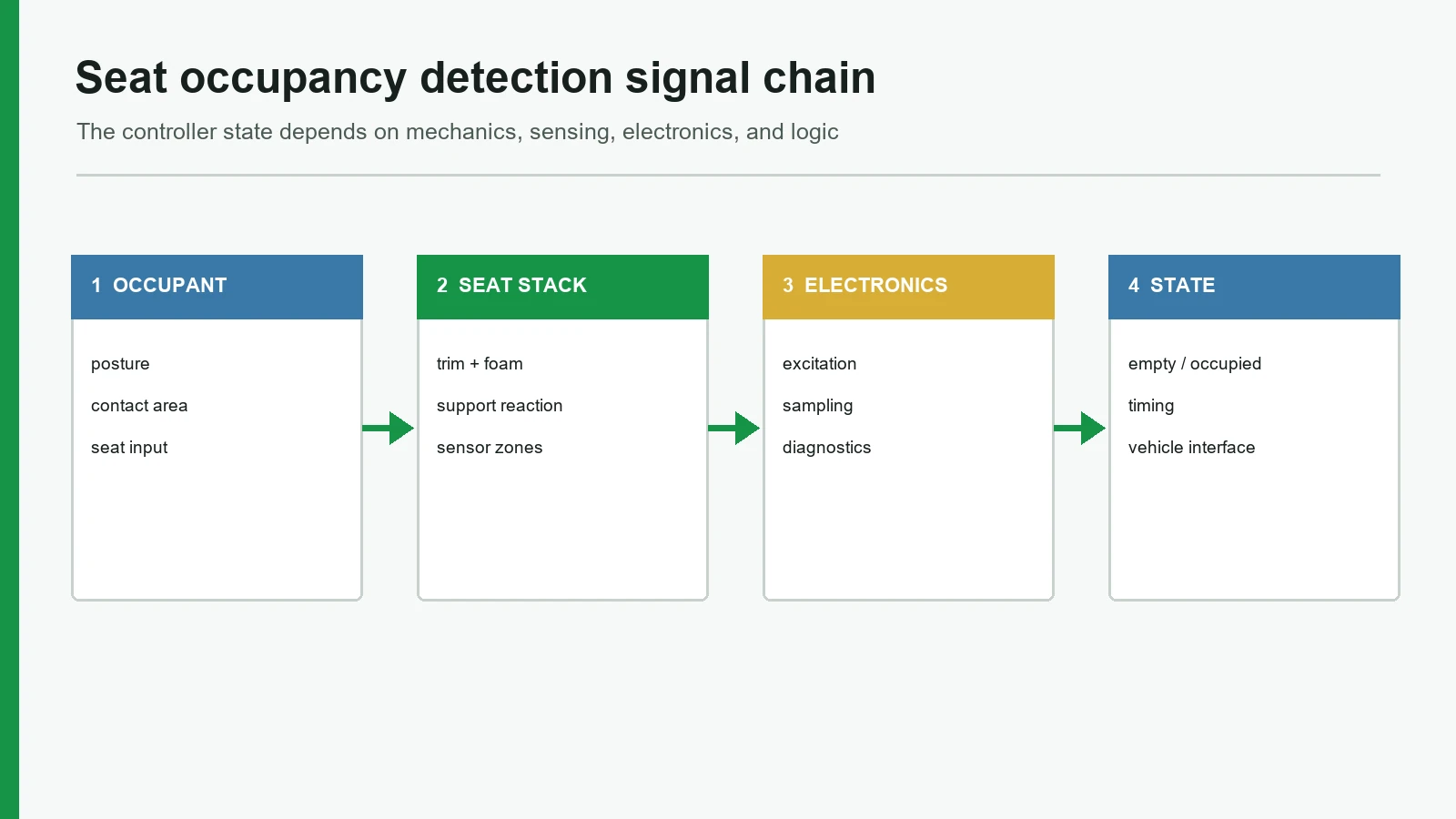
How Does a Seat Occupancy Sensor Work From Load to State?
The operating sequence has five distinct stages: load transfer, sensor response, electrical conversion, decision logic, and system output. Keeping them separate makes design reviews and fault analysis much easier.
1. The seat converts body load into local force
An occupant’s total weight is not applied uniformly to one sensor point. Posture, clothing, cushion contour, feet on the floor, seat-back angle, and lateral position change the force distribution. The foam and trim then spread that distribution across the sensing zones. This is why “detect a 40 kg person” is incomplete: the drawing must also define the seat build, posture, load applicator or surrogate, zone, dwell, and environmental condition.
2. A contact mat or FSR produces an electrical change
A contact-closure mat uses conductive features separated by a spacer or controlled gap. Sufficient local compression brings the conductors together. The output is usually open/closed per zone, although the released and actuated resistance limits still require definition.
An FSR is resistive rather than binary. Its resistance is high with little or no applied force and falls as force increases. In one product-specific integration example, Tekscan reports greater than 2 MΩ unloaded and about 25 kΩ at the sensor’s peak measurement load. Those numbers illustrate the direction and scale of change for that sensor and circuit; they are not a JASPER value or a seat threshold. Tekscan’s electrical integration guide also calls for calibration with the completed assembly, or as close to it as possible.
| Sensing element | Raw behavior | Useful when | Main limitation |
|---|---|---|---|
| Contact-closure zone | Open circuit changes to closed contact | A stable occupied/unoccupied input is enough | The threshold is largely mechanical and tied to the stack |
| Single-zone FSR | Resistance falls with applied force | An adjustable analog boundary or relative-load trend is useful | Output depends on force distribution, interface circuit, dwell, and calibration |
| Multi-zone contact mat | Several independent open/closed states | Coverage or a basic spatial pattern matters | More traces, pins, combinations, and fault cases |
| Multi-zone FSR | Several analog channels or a resistive array | Load distribution is needed | Channel matching, calibration data, and software complexity increase |
Force distribution, actuator area, actuator material, and placement can substantially alter an FSR response. An FSR is not a load cell or precision pressure transducer. A stable fixture can make its response useful; an uncontrolled seat stack can make a precise-looking resistance value misleading.
3. The interface circuit turns the raw response into a usable signal
A contact mat can feed a protected digital input or diagnostic resistor network. An FSR commonly enters a voltage divider, transimpedance or conductance circuit, amplifier, and analog-to-digital converter. Multi-zone mats require independent channels or a scanning network. A conditioned module may instead send a digital state and diagnostic information over a defined vehicle interface.
The interface contract should state the supply and reference tolerances, pull-up or feedback components, input protection, sample rate, filter, ADC range, connector pinout, open/short detection, and allowable leakage. “Analog output” is not a complete electrical specification.
4. Thresholds, hysteresis, and time qualification create a state
One threshold tends to chatter when the signal sits near the boundary. A two-threshold rule provides hysteresis:
If state is EMPTY and signal ≥ T_on for t_on: candidate → OCCUPIED
If state is OCCUPIED and signal ≤ T_off for t_off: candidate → EMPTY
Constraint for a rising-with-load signal: T_off < T_on
T_on and T_off separate the decision in amplitude. t_on and t_off qualify it in time. They solve different problems. Hysteresis uses distinct rising and falling thresholds to reduce sensitivity near a noisy boundary, as shown in Texas Instruments’ comparator guidance. Time qualification rejects short events caused by bounce, road vibration, entry/exit motion, or a shifting occupant; Microchip AN1450 provides a hardware/software debouncer example with separately set rising and falling delays.
| State | Minimum meaning | Typical next check |
|---|---|---|
| Empty | A valid input remains inside the approved empty region | Continue diagnostics and watch for an activation candidate |
| Occupied | A valid signal or zone pattern meets the occupied rule | Combine with buckle, seat position, or other program inputs as required |
| Transitional | The input is changing or has not satisfied its time rule | Hold the prior safe state or follow the defined transition policy |
| Unknown | Startup or insufficient data prevents a decision | Complete initialization and plausibility checks |
| Fault | Electrical or logical checks reject the input as valid | Report diagnostics and follow the system safety response |
The controller should not silently map a disconnected sensor to “empty.” Open circuit, short circuit, out-of-range analog values, stuck zones, implausible combinations, and communication loss need explicit treatment. The required fallback comes from the system safety concept, not from a generic blog rule.
5. The controller publishes a bounded output
The output may be one bit, a state enumeration, a relative-load value, per-zone data, a diagnostic code, or a conditioned message. That output can support a seat-belt reminder, passenger-air-bag suppression logic, driver-presence confirmation, or comfort control. “Support” matters: downstream logic may require other inputs and separate validation.
Seat Occupancy Sensor Types and the Right Decision Boundary
Architecture selection should start with the decision the system must make. A pressure mat is a strong fit for thin, seat-integrated presence detection, but it is not automatically the best choice for calibrated weight, living-being detection, or detailed occupant classification.
| Architecture | Information available | Strong starting use | Where it is not the best choice |
|---|---|---|---|
| Contact pressure mat | One or more binary zones | Simple occupied/unoccupied state for a defined seat stack | When the system needs continuous load information or overlapping empty/occupied patterns cannot be separated |
| FSR seat sensor | Relative analog load per element or zone | Adjustable threshold, trend, or coarse distribution | When traceable absolute weight and a tight error budget are required |
| Multi-zone pressure/FSR mat | Spatial activation or analog pattern | Wider coverage, posture clues, or zone plausibility | When extra channels and calibration do not improve the decision |
| Structural load or strain sensing | Load transferred through a rail, bracket, or frame | More controlled force measurement | When the mechanical load path cannot be isolated or packaging changes are unacceptable |
| Capacitive passenger presence sensor | Electric-field response associated with an occupant or child restraint | Classification strategies that do not rely only on cushion force | When conductive materials, grounding, moisture, or seat options cannot be controlled adequately |
| Camera or cabin radar | Position, object/person features, motion, or vital-sign-related information, depending on system | Living-being detection, out-of-position analysis, or whole-cabin coverage | When privacy, line of sight, compute cost, packaging, or feature scope favors a simpler seat input |
Seat occupancy architectures include structural load measurement, resistive pressure sensing, capacitive classification, camera-based interior sensing, and cabin radar. Each route has a different output, installation burden, diagnostic boundary, and validation plan; no technology is universally superior.
When a pressure mat is not the recommended construction
Do not default to a pressure mat when the requirement is to measure absolute occupant weight across broad posture and temperature variation, detect a breathing child outside the seat, classify occupants from visual posture, or cover the entire cabin with one sensing node. Structural load sensing, capacitive classification, camera, radar, or sensor fusion may fit those decisions better. A thin mat remains valuable when the required state, seat load path, cost envelope, and validation plan are aligned with what it can actually observe.
How Sensing Zones and Seat Installation Change the Result
Sensing zones define where the system can observe load. One large zone simplifies routing but provides little spatial information. Several smaller zones can cover the rear, center, and front cushion separately, yet every added channel creates another trace, connector pin, tolerance, diagnostic case, and state combination.
Zone geometry should come from load-distribution data collected on representative seat builds. It should not be copied from a flat catalog mat. The published EPO architecture uses distributed elements to extend the active area and address out-of-position loading; that is a useful principle, not a production drawing for another program. EP 1531093 A1
| Failure chain | Observable effect | Correct engineering response |
|---|---|---|
| Trim or foam preloads a zone | Empty baseline moves toward the occupied region | Change placement or stack; characterize preload before tuning software |
| Cushion groove bypasses a zone | Required occupied case produces too little signal | Move or resize the zone using mapped load data |
| Heater, adhesive, or hard carrier bridges the active area | Force reaches the element inconsistently | Control layer geometry and use the production-intent stack in tests |
| Empty and occupied distributions overlap | Threshold changes trade false positives for missed detection | Redesign the load path, zones, or sensing architecture; filtering cannot create separation |
| Tail bends at the cushion edge | Intermittent open or resistance change appears during seat motion | Define bend radius, strain relief, clamp points, and motion testing |
| Long dwell shifts an FSR response | State margin changes while the load remains applied | Include dwell/recovery cases and use a sensor or logic strategy suited to the requirement |
A pressure mat occupancy sensor should be located by datum, orientation, adhesive boundary, and allowable wrinkle or fold—not by a vague note such as “under the foam.” Production controls must also protect the tail during trim installation and seat adjustment.
Outputs, Use Cases, and OEM Integration Boundaries
The component drawing and the controller interface control document should agree on the output. Common choices are a dry contact, diagnostic contact network, resistance range, conditioned voltage, independent zone channels, or a digital state. For each choice, specify empty/occupied limits, invalid ranges, timing, connector pinout, supply/reference conditions, and the party responsible for calibration.
Seat-belt reminder occupancy input
A seat-belt reminder combines occupancy information with buckle status and warning logic. IEE publicly describes foil-based pressure sensors for this function. NHTSA’s 2024 rulemaking also discusses the practical challenge of cargo, pets, folding seats, and rear bench layouts. The mat does not define the warning by itself. IEE SBR factsheet and the NHTSA final rule provide the respective technology and regulatory context.
Front-passenger suppression or occupant classification
In the United States, 49 CFR 571.208 evaluates the vehicle’s automatic-suppression feature with defined restraints, dummies, seat positions, and procedures. Under the cited option, specified child-restraint cases must deactivate the air bag and a 5th-percentile adult-female case must activate it. This is vehicle-system evidence—not a universal sensor trigger or a component certificate. See 49 CFR 571.208, S19–S22.
Driver presence and comfort functions
Driver-presence input can gate a program-defined function or support power management; seat occupancy can also inform heating, ventilation, or cabin configuration. These uses still need explicit fault behavior. A comfort controller may tolerate uncertainty that a safety-related function cannot. The system owner must document the difference through the applicable automotive integration process.
Standards and Validation for Seat Occupancy Detection
No single standard supplies a ready-made pressure-mat threshold. The vehicle program selects applicable regulations and derives component requirements from the mounting location, function, safety analysis, and validation plan.
| Reference | Relevant scope | What it does not prove |
|---|---|---|
| 49 CFR 571.208 | U.S. vehicle occupant crash protection, including specified suppression/activation tests | That a bare mat is compliant or that one trigger force works in every seat |
| ISO 16750-1:2023 and Parts 2–5 | Mounting-location-based electrical, mechanical, climatic, and chemical loads for road-vehicle E/E equipment | That every listed test or severity applies unchanged to this component; EMC is outside the series |
| ISO 20653:2023 | Road-vehicle enclosure IP codes and confirmation tests | An IP rating for an untested film, connector, or changed assembly |
| ISO 26262:2018 series | Functional-safety lifecycle for safety-related road-vehicle E/E systems | A generic ASIL for every occupancy sensor or automatic approval of the vehicle function |
Installed-stack test matrix
| Test family | Vary | Measure | Acceptance evidence |
|---|---|---|---|
| Baseline separation | Multiple sensors, cushions, trim builds, seat positions | Empty distribution, occupied distribution, margin | Approved limits with sample count and statistical rationale |
| Position and posture | Center, edge, ingress/egress, required occupant/load surrogates | Zone pattern, activation/release, transitions | No prohibited overlap; defined transitional behavior |
| Electrical faults | Open, short, leakage, connector interruption, supply/reference limits | Diagnostic state and recovery | Interface-control and safety requirements met |
| Mechanical durability | Repeated loading, tail motion, assembly/reassembly | Drift, damage, intermittent faults | Program-specific cycle profile and post-test limits |
| Environment | Temperature, humidity, thermal cycling, relevant fluids | Baseline shift, state margin, insulation, recovery | Applicable ISO 16750/OEM severity with report traceability |
| Enclosure protection | Exact sealed assembly, connector, and cable exit | Ingress and post-test function | ISO 20653 or OEM method for the tested configuration |
Calibration must use the completed assembly, or a close production-intent equivalent. Tekscan makes that point explicitly for FSR integration because part variation and mechanics affect the force-to-output relationship. Component checks can be planned through JASPER’s testing and quality-control capability, but vehicle-level validation remains with the OEM, Tier 1, or designated system owner.
Project Inputs an OEM Should Define Before Sensor Design
A useful request package replaces the phrase “detect a passenger” with testable inputs:
- Seat position, vehicle class, target markets, and system function;
- Required output: contact, resistance, voltage, independent zones, or conditioned message;
- Definitions for empty, occupied, transitional, unknown, and fault states;
- Seat drawing, trim and foam sections, heater/ventilation layers, support, and sensor datum;
- Required occupant/load surrogates, posture, position, dwell, and release cases;
- Zone coverage, forbidden areas, tail route, bend radius, connector, and pinout;
- Controller circuit, sample rate, thresholds, hysteresis, time rules, and diagnostics;
- Environmental, chemical, ingress, durability, assembly, and change-control requirements;
- Sample count, seat-build variation, fixture, acceptance method, and report format; and
- Ownership of component calibration, seat validation, vehicle compliance, and functional safety.
Teams deciding between analog and contact behavior can review how a force-sensing resistor works and the seat occupancy sensor mat or FSR seat pressure sensor routes. When the inputs above are ready, send the controlled drawing package to JASPER Contact Engineering, referring to the custom options linked near the start of this article.
<!--
Frequently Asked Questions
How does a seat occupancy sensor work in a car seat?
The trim and foam transfer seat load to a contact mat, FSR, or other sensing element. Electronics convert the response into a signal, reject invalid inputs, and apply thresholds, hysteresis, and time qualification before reporting empty, occupied, transitional, unknown, or fault.
Is a seat occupancy sensor the same as a weight sensor?
No. Occupancy detection may need only a reliable state, while weight sensing implies a calibrated load measurement and defined error budget. A pressure mat or FSR can support relative-load decisions, but absolute measurement may require a controlled structural load path and different sensor architecture.
What is the difference between a contact pressure mat and an FSR seat sensor?
A contact mat closes one or more electrical paths after sufficient compression. An FSR produces a continuous resistance change as force changes. Contact mats simplify binary detection; FSRs allow an adjustable analog boundary but add circuit, calibration, drift, and load-distribution considerations.
Can a passenger presence sensor distinguish a person from luggage?
Not by name alone. Separation depends on the sensor principle, zones, signal resolution, seat mechanics, required object set, and classification logic. If required occupant and cargo distributions overlap, the program needs a different zone layout, another sensing technology, or additional inputs.
Where is a pressure mat occupancy sensor installed?
Possible positions include between trim and foam, within the cushion stack, or at another controlled A- or B-surface location. The correct datum depends on foam, heater and ventilation layers, support stiffness, assembly sequence, tail protection, and measured load distribution.
Is there a universal trigger weight for seat occupancy detection?
No. A person’s weight is distributed through posture, trim, foam, and the support structure. The program must define its required occupant or load surrogates, seat positions, environment, dwell, margin, and controller timing, then derive limits from representative builds.
Which standards apply to an automotive seat occupancy sensor?
The applicable set is program-specific. Common references include 49 CFR 571.208 for U.S. vehicle occupant protection, ISO 16750 for vehicle E/E environmental loads, ISO 20653 for enclosure IP tests, and ISO 26262 for the functional-safety lifecycle. None certifies a bare mat automatically.
When is a pressure mat occupancy sensor not the best option?
A pressure mat is usually the wrong default when the system needs traceable absolute weight, whole-cabin coverage, living-being detection away from the cushion, or rich occupant posture classification. Structural sensing, capacitive detection, camera, radar, or sensor fusion may better match those decisions.
Technical References
- Source: 49 CFR 571.208 occupant crash protection. Accessed 2026.
- Source: ISO 16750 road vehicle electrical equipment environmental conditions. Accessed 2026.
- Source: ISO 20653 road vehicle enclosure protection. Accessed 2026.
- Source: ISO 26262 road vehicle functional safety. Accessed 2026.
- Source: NHTSA seat belt reminder final rule. Accessed 2026.
- Source: EPO EP 1531093 A1. Accessed 2026.
- Source: IEE’s vehicle occupant sensing factsheet. Accessed 2026.
- Source: Tekscan’s electrical integration guide. Accessed 2026.
- Source: Interlink FSR 400 Series Integration Guide. Accessed 2026.
- Source: Texas Instruments’ comparator guidance. Accessed 2026.
- Source: Microchip AN1450. Accessed 2026.
- Source: single-FSR seat occupancy study. Accessed 2026.
- Source: capacitive occupant-classification system. Accessed 2026.
- Source: Bosch’s interior-sensing overview. Accessed 2026.
- Source: EP 1531093 A1. Accessed 2026.
- Source: IEE SBR factsheet. Accessed 2026.
- Source: NHTSA final rule. Accessed 2026.
- Source: 49 CFR 571.208, S19–S22. Accessed 2026.
- Source: 49 CFR 571.208. Accessed 2026.
- Source: ISO 16750-1:2023. Accessed 2026.
- Source: ISO 20653:2023. Accessed 2026.
- Source: ISO 26262:2018 series. Accessed 2026.
- Source: TE Connectivity seat-position sensor benchmark. Accessed 2026.
- Source: Tekscan A201. Accessed 2026.
Define the seat state before selecting the sensor
Send the required states, seat construction, sensing zones, output boundary, diagnostics, environment, and validation owner.