
An automotive human-machine interface is the physical and electronic assembly through which a driver or passenger receives vehicle information and issues commands. For OEM and Tier-1 teams, the integration decision covers the display, touch sensor, cover lens or overlay, tactile controls, circuit, flex tail, connector, bracket, enclosure, grounding, and sealing interfaces. The right construction depends on vehicle function, viewing conditions, mounting location, touch-use case, environmental loads, EMC targets, and validation ownership. Treat these elements as one controlled stack. JASPER's manufacturing boundary is the front-panel and HMI hardware assembly; cockpit software, PLC/SCADA programming, and ADAS control algorithms remain outside that boundary.
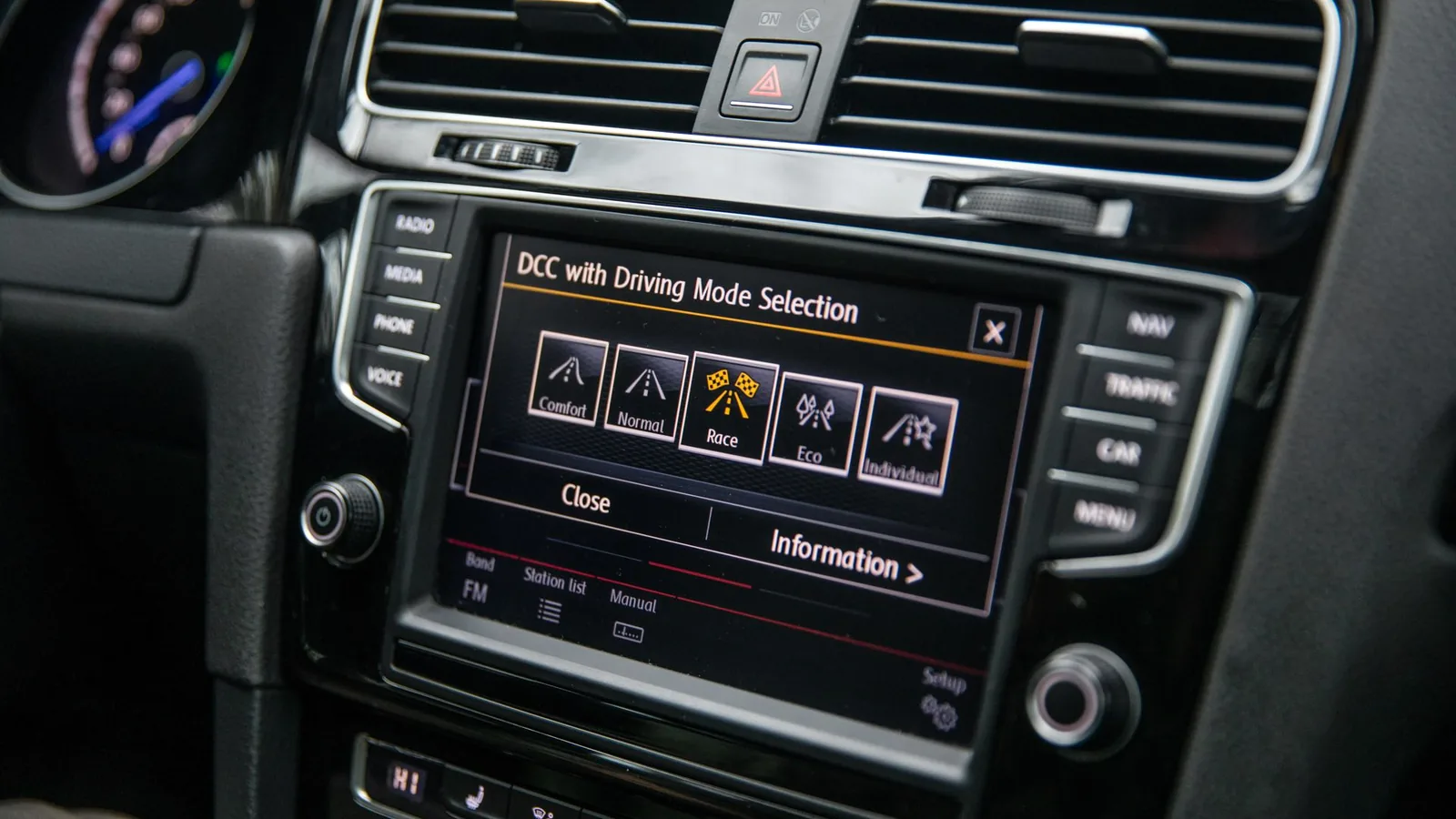
Quick decision table for automotive HMI hardware
The first decision is not screen size. It is the function's driver-attention demand and the consequence of a missed, delayed, or unintended input. That classification determines which hardware feedback paths and validation evidence belong in the design.
| Vehicle function | Preferred hardware approach | Primary integration risk | Release evidence |
|---|---|---|---|
| Required tell-tale or driver-status information | Dedicated, continuously visible display region or regulated indicator | Occlusion, loss of contrast, ambiguous status, common-power failure | Optical test, mode/fault-state review, applicable market requirement |
| Frequent control used while moving | Shaped physical control, rotary input, or fixed-position tactile key; touch may supplement it | Eyes-off-road demand, false touch, no confirmation | Human-factors study, force/travel sample, haptic or tactile verification |
| Navigation, media, and configurable settings | Display plus projected-capacitive touch, with lockouts where required | Reflection, latency, wet/glove behavior, menu demand | Ambient-light optical test, touch matrix, NHTSA/ISO review |
| Passenger-only entertainment | Display and touch optimized for passenger viewing and privacy | Driver visibility, unintended access, thermal load | Viewing-zone check, content-state review, thermal test |
| ADAS status, warning, or takeover communication | Dedicated visual path with coordinated audible or haptic channel | Stale or missing state, priority conflict, shared-interface failure | State-transition test, message-priority review, fault-injection plan |
The NHTSA Visual-Manual Driver Distraction Guidelines recommend restricting tasks that are inherently distracting or exceed the guideline's acceptance criteria while a vehicle is moving. Hardware can preserve fixed-location controls, distinct feedback, and visible status when software states change.
What is a human-machine interface in a car?
A human-machine interface in a car includes every physical and software channel through which occupants and the vehicle exchange information. The NIST HMI definition covers hardware or software used to interact with a controller. In a vehicle, that boundary can include a cluster, center display, touch surface, steering-wheel switch, tell-tale, rotary controller, haptic actuator, audible warning, and the logic behind them.
This guide narrows the subject to hardware that can be drawn, assembled, and validated. A front-panel supplier may integrate the lens, overlay, display, touch sensor, tactile keys, circuit, adhesive, gasket, flex tail, connector, and enclosure interface. The Tier-1 remains responsible for the complete module's vehicle interface unless the contract assigns work differently.
See What Is an HMI Panel? Hardware and OEM Guide for broader context. JASPER's HMI assemblies page describes the commercial sourcing route, not technical evidence.
Automotive HMI hardware works as a controlled front-to-back stack
An automotive HMI succeeds when optical, mechanical, and electrical interfaces share datums and load paths. The screen is not the system. Release the stack as an assembly, not a collection of nominal rectangles.
- Cover lens or graphic overlay: Defines the visible surface, styling, icons, coating, cleanability, and first optical interface.
- Optical bond or controlled air gap: Couples transparent layers; thickness, edge termination, modulus, and cure affect appearance and stress.
- Touch sensor: Converts input into signals. Electrode pattern, cover thickness, grounding, and controller tuning work together.
- Display module: Contains the active panel, backlight or emissive layer, driver electronics, frame, and keep-outs.
- Tactile control layer: Domes, molded keys, rotary devices, or switches give selected functions location and actuation feedback.
- Circuit and interconnect: Flex, PCB, FPC tails, data links, power, and ground connect the user surface to module electronics.
- Support and enclosure interface: Brackets, gaskets, fasteners, ribs, heat paths, and connector retention carry loads.
Control the viewing-area center separately from the bezel when tolerances differ. Define no-pressure zones over the active area, chip-on-film region, and light guide. Include adhesive, gasket compression, bracket flatness, and fastener sequence in the Z-stack analysis. High-Performance HMI Hardware Design provides related context; the program drawing remains contractual.
Optical performance must be measured in vehicle viewing conditions
Display luminance alone does not establish readability. Cover reflections, black-mask geometry, touch-sensor conductors, air interfaces, polarizers, coatings, viewing angle, backlight control, and ambient illumination determine what the driver sees. The released optical specification should name the measurement geometry, ambient source, viewing position, display state, temperature condition, and acceptance metric.
SAE J1757/1_202108 provides methods for measuring vehicular-display optical performance under typical automotive ambient illumination, with a focus on high ambient contrast ratio. Its public scope explicitly does not set one universal compliance threshold. ISO 15008:2017 addresses image quality and legibility for dynamic visual information presented to passenger-car drivers, but its stated exclusions include head-up displays, rear-view images, maps, and several quasi-static items. Engineers should map each display region to the correct test scope rather than applying one standard label to the whole cockpit.
Optical bonding removes an internal air gap and can reduce internal reflection while preventing dust from occupying that cavity. It also makes rework, differential expansion, edge sealing, and mura control more demanding. Air-gap construction can be appropriate when serviceability and cost outweigh maximum ambient contrast and the cavity can be sealed and controlled.
Material data must retain its test condition. The 3M ACO 05U technical data sheet reports 0.16% haze for uncured ACO 05U-250 film on LCD glass using ASTM D1003-92. That is one material sample, not a bonded display. Test the production geometry after lamination, conditioning, and final assembly.
Touch controls need tactile backup when task risk demands it
Projected-capacitive touch suits reconfigurable content and large display areas, but the controller cannot be selected independently from the sensor and front surface. Cover thickness, electrode geometry, ground reference, display noise, water, gloves, adjacent metal, and EMC filters alter signal margin. Microchip's maXTouch family guide shows controller-specific wet, glove, and noise behavior. Tune and verify the production cover, coating, display, enclosure, and harness.
Frequently used or consequence-bearing controls deserve a distinct confirmation path. A shaped button or rotary device gives the user a fixed location and mechanical cue. A metal-dome or discrete-switch construction can create a snap event; a haptic actuator can confirm a touch surface only when its mechanical coupling, drive waveform, latency, noise, and fault behavior are controlled. SAE J3280_202306 covers when and how haptic interfaces can support driver-vehicle interaction in light vehicles.
Touch-only is a poor default when the driver must find a control by feel, when a screen state can hide the control, when gloves or surface contamination cannot be bounded, or when loss of the display would remove an essential input. The right allocation comes from task analysis and vehicle-level safety work, not a styling preference. Human-factors teams can connect these hardware choices to HMI Ergonomics and Human Factors for Industrial Equipment while applying automotive-specific NHTSA, ISO, SAE, and OEM criteria.
The automotive environment must be specified by mounting location
“Automotive grade” is not a test condition. Instrument-panel sunlight exposure, door moisture, steering-wheel vibration, center-console spills, passenger impact, defroster airflow, cleaning chemicals, and nearby RF sources create different loads. The Tier-1 should issue a location-specific profile before the assembly supplier freezes the adhesive, overlay, gasket, connector, and support structure.
ISO 16750-3:2023 addresses mechanical loads for vehicle electrical and electronic equipment; ISO 16750-4:2023 addresses climatic loads. Both official scopes tie recommended tests and requirements to the mounting location. ISO 20653:2023 defines road-vehicle enclosure protection against foreign objects, water, and access. None of these scopes justifies assigning a universal temperature range, vibration profile, or IP code to every cabin HMI.
Application-risk matrix
| Risk condition | Likely hardware failure path | Design control | Validation input | Decision owner |
|---|---|---|---|---|
| Direct sun and high cabin temperature | Low ambient contrast, discoloration, adhesive creep, polarizer stress | Optical stack, coating, bond line, heat path, dimming strategy | Solar/thermal profile, viewing geometry, conditioned optical measurement | OEM/Tier-1 optical and environmental teams |
| Condensation, wet fingers, or spills | False touch, corrosion, trapped moisture, edge contamination | Edge seal, gasket path, drainage, touch tuning, connector placement | Fluid type, ingress target, recovery behavior, wet-touch matrix | Tier-1 with touch and assembly suppliers |
| Vibration and shock | FPC cracking, connector fretting, display-frame load, fastener loosening | Strain relief, support points, connector retention, compliant pads | Mounting-location spectrum, fixture, powered state, functional monitoring | Tier-1 validation owner |
| Repeated cleaning and sunscreen exposure | Legend wear, gloss change, coating damage, bond attack | Surface material, ink system, hard coat, edge design | Named chemicals, concentration, wipe method, cycles, dwell, temperature | OEM materials team and assembly supplier |
| Occupant ESD | Reset, false input, permanent controller damage | Discharge path, shielding, ground strategy, filter network, bezel geometry | Contact/air points, powered modes, recovery class | Tier-1 EMC owner |
| Supplier or material change | Color shift, touch retuning, bond or process drift | Approved-source list, critical characteristics, change notification | Delta qualification and PPAP submission level | Tier-1 supplier quality |
Use production-intent materials and tooling for environmental tests. A flat coupon cannot reproduce bezel stress, cable restraint, ground paths, or trapped air.
Validation reference scope map
Standards names are useful only when the program also identifies scope, revision, method, severity, fixture, and acceptance criteria.
| Reference | Public scope used here | Program input to freeze |
|---|---|---|
| ISO 15005:2017 | Driver/TICS dialogue | Function and motion state |
| ISO 15008:2017 | Dynamic driver-display legibility | Geometry and optical target |
| SAE J1757/1_202108 | Vehicular-display metrology | Ambient and viewing setup |
| SAE J3280_202306 | Driver haptic interaction | Use case and feedback criteria |
| ISO/TS 16951:2021 | On-board message priority | States and precedence |
| ISO 16750-3:2023 | Mechanical loads | Mounting location and fixture |
| ISO 16750-4:2023 | Climatic loads | Location profile and powered state |
| ISO 20653:2023 | Enclosure ingress protection | Required IP code and boundaries |
| ISO 10605:2023 | Vehicle/module ESD | Points, modes, and recovery class |
| ISO 11452-2:2019 | Component RF immunity | Harness, field, and monitoring |
| CISPR 25:2021 | On-board receiver protection | Bands, limits, and setup |
| UN Regulation No. 10 | EMC type approval | Markets and approval route |
| UN Regulation No. 121 | Controls, tell-tales, indicators | Regulated functions and markets |
| IATF 16949:2016 | Automotive quality-system context | Customer-specific revision |
| ASTM D1003-92 | Haze method in the cited OCA data | Specimen and assembly condition |
| IEC 61000-4-6 | Conducted RF method in the cited touch example | Applicability to screening |
Connector and tail routing are part of the released HMI drawing
An FPC tail is an electrical path and a mechanical component. Its exit location, bend zone, neutral-axis behavior, stiffener, connector insertion direction, retention, service loop, shield termination, and assembly access must appear in the interface drawing. Do not use the tail to pull the display into position or to react enclosure tolerance.
The Molex FPC design guide recommends fillets at conductor-pad transitions, soft direction changes rather than sharp corners, and conductor routing perpendicular to flexing bends where possible. A fixed bend-radius rule is still inappropriate without the flex construction, copper thickness, layer count, bend type, temperature, and required cycles. Obtain the approved limit from the selected flex and connector suppliers.
High-speed display links need a controlled channel across PCB traces, connector launches, cable, and return path. A TI FPD-Link III EMC application note calls for direct routing, minimal stubs, and 100 Ω ±5% total differential impedance for that interface. Do not copy the value to MIPI DSI, OpenLDI, Ethernet, USB, or another link. Use its own channel specification.
The drawing should also freeze pin numbering, mating connector, contact finish, keying, latch or connector-position assurance, insertion clearance, maximum component envelope, cable-shield termination, and ground domain. Validate the production harness, not a bench cable chosen for convenience.
EMC must be validated on the complete hardware configuration
The display, touch controller, backlight converter, haptic driver, flex tail, cable shield, enclosure, and ground bonds form one EMC system. A controller evaluation board passing a laboratory test does not qualify the assembled HMI. Mechanical revisions can change return paths and touch sensitivity even when the schematic is unchanged.
CISPR 25:2021 covers radio-disturbance measurements from 150 kHz to 5,925 MHz for protecting on-board receivers. Its scope notes that limits may be modified by agreement between the vehicle manufacturer and supplier. ISO 11452-2:2019 specifies component immunity testing in an absorber-lined shielded enclosure with the device under test and wiring harness exposed to continuous narrowband fields. ISO 10605:2023 covers ESD from assembly, service staff, and occupants for electronic modules and complete vehicles. Target markets may also make UN Regulation No. 10 relevant to vehicle or electrical/electronic-subassembly approval.
Freeze the harness, cable length, shield termination, support electronics, software state, display content, touch mode, supply mode, and performance criteria before lab booking. Exercise touch during immunity tests. Monitor false activations, missed touches, resets, display artifacts, communication errors, and recovery. TI's noise-tolerant capacitive-touch reference design demonstrates 10 Vrms conducted RF immunity for one design under IEC 61000-4-6; it is not evidence for another controller or finished panel.
A human-machine interface in ADAS systems needs explicit state and fault paths
A human-machine interface in ADAS systems communicates availability, active mode, requests, limitations, transitions, and faults. The hardware implication is straightforward: the display and indicator path must support the states that vehicle-level safety and human-factors teams define, including degraded operation. A shared screen may be suitable for rich context, but the program must decide what remains visible if that screen, backlight, touch controller, data link, or power domain fails.
ISO/TS 16951:2021 supplies procedures for prioritizing on-board messages, including warnings and system status. UN Regulation No. 121 addresses identification of controls, tell-tales, and indicators for applicable markets. These sources do not assign a universal ADAS layout. The OEM and Tier-1 must translate the vehicle concept into display zones, indicators, alternate channels, diagnostics, and validation cases.
Human-machine interface considerations for future mobility extend beyond larger displays. Automated-driving features, passenger displays, and reconfigurable controls increase the need for controlled optical zones, independent status paths, diagnostics, and disciplined change management.
Tier-1 validation ownership must be assigned before design freeze
The Tier-1 normally owns the complete supplied module's compliance to the OEM specification, even when display, touch, lens, circuit, and assembly work come from separate sources. Contract language can allocate tasks differently, so the statement of work needs a responsibility matrix, deliverables, sample quantities, fixtures, acceptance authority, and change-control route.
| Activity | OEM | Tier-1 module owner | Display/touch suppliers | HMI assembly supplier |
|---|---|---|---|---|
| Vehicle use cases, target markets, regulated functions | Approves and supplies | Translates into module requirements | Provides component constraints | Reviews manufacturability inputs |
| Optical and environmental targets | Approves vehicle-level targets | Defines module test plan and acceptance criteria | Supplies characterized parts and limits | Controls stack, process, and assembly samples |
| EMC setup and functional-performance status | Approves vehicle interface | Owns DUT configuration, harness, monitoring, and results | Supports controller/link behavior | Implements grounding, shielding, and build controls |
| DV/PV samples and change levels | Approves gates | Controls configuration and traceability | Controls component revisions | Builds traceable production-intent assemblies |
| PPAP and production release | Defines customer submission | Owns submission and supplier evidence | Supplies required records | Supplies process, inspection, and material records within scope |
AIAG's PPAP description defines production part approval as the process used to show that engineering design records and specification requirements are consistently met. The IATF customer-specific requirements repository shows why the quality plan must name the OEM document and revision rather than citing IATF 16949 generically.
Start testing and validation planning before tooling release. Use prototyping and sample approval to close optical appearance, touch tuning, tactile feel, connector access, fit, and assembly sequence. The HMI Panel Assembly Design Checklist supports review; the OEM drawing and Tier-1 test specification control the program.
Project-input checklist for an automotive HMI RFQ
A useful RFQ exposes missing interfaces before pricing or tooling. Include these controlled inputs:
- Vehicle function, user group, driver/passenger location, and operating state.
- Display size, active area, resolution, interface, backlight power, viewing direction, and supplier drawing.
- Cover-lens or overlay drawing, visible area, black mask, icons, coatings, color/gloss limits, and cosmetic zones.
- Touch technology, controller, cover thickness, wet/glove/stylus cases, allowed false/missed-input behavior, and tuning owner.
- Tactile-control locations, switch technology, target force/travel or torque profile, illumination, and confirmation method.
- Complete XY datum scheme, Z-stack, component keep-outs, no-pressure zones, bracket, fasteners, gasket, and enclosure CAD.
- FPC and harness drawings, pinout, mating connector, cable length, shield termination, ground domains, bend restrictions, and service access.
- Mounting-location temperature, humidity, solar, vibration, shock, fluid, cleaning, ingress, ESD, emissions, and immunity requirements with methods and severities.
- Target markets, applicable regulations, OEM specifications, DV/PV plan, PPAP level, special characteristics, traceability, and change-notification rules.
- Prototype stages, annual volume, ramp timing, packaging, inspection data, and acceptance authority.
Teams with a controlled front-panel drawing and interface stack can send drawings for engineering review. Include the display size, front-panel drawing, interface stack, environment, and annual volume. When the specification is ready for commercial review, request an engineering quote.
Frequently asked questions
What is a human-machine interface in a car?
A human-machine interface in a car is the combined hardware and software through which occupants receive vehicle information and issue commands. Its hardware can include displays, touch sensors, buttons, rotary controls, overlays, tell-tales, haptic actuators, circuits, connectors, and enclosures. This guide focuses on the manufacturable hardware assembly and its vehicle interfaces.
Is a touchscreen enough for every automotive HMI function?
No. A touchscreen suits configurable navigation, media, and settings, but frequent or consequence-bearing driver controls may need a fixed-position tactile or rotary input. The allocation should reflect driver-attention demand, contamination and glove cases, fault behavior, and applicable NHTSA, ISO, SAE, OEM, and market requirements.
When should an automotive display use optical bonding?
Optical bonding is useful when ambient contrast, contamination control, thin construction, or structural coupling outweigh rework and process complexity. It is not automatically better for every HMI. Compare a bonded and air-gap production-intent stack after thermal, humidity, optical, touch, and cosmetic conditioning before releasing the construction.
How should sunlight readability be validated?
Validate the finished display, touch, lens, coating, and enclosure stack at the specified viewing geometry and automotive ambient-light condition. Record display state, temperature, luminance, reflections, and ambient contrast. SAE J1757/1 supplies measurement methods, but the OEM or Tier-1 must set application-specific acceptance thresholds.
Which environmental standards apply to automotive HMI hardware?
Common scope references include ISO 16750-3 for mechanical loads, ISO 16750-4 for climatic loads, and ISO 20653 for enclosure protection. Applicability and severity depend on the mounting location, vehicle category, target market, and OEM specification. A standard number without the actual method, level, fixture, and acceptance criteria is incomplete.
How should an HMI flex tail be routed?
Route the tail without using it as a structural tie. Define the exit, bend zone, stiffener, connector access, strain relief, service loop, shield termination, and keep-outs on the drawing. Use soft conductor direction changes and obtain the permitted bend radius and cycle limit from the selected flex construction and supplier.
Who owns automotive HMI validation in a Tier-1 program?
The Tier-1 module owner normally coordinates integrated validation against the OEM specification, while component and assembly suppliers provide evidence within their contracted scopes. The statement of work must assign test planning, fixtures, samples, failure analysis, acceptance, PPAP records, and change control; assumptions are not a responsibility matrix.
What information does an HMI assembly supplier need for an RFQ?
Provide the display size and drawing, front-panel artwork and mechanical drawing, touch and tactile requirements, complete interface stack, connector and tail data, enclosure CAD, environmental and EMC specifications, validation plan, annual volume, prototype stage, target markets, and acceptance owner. Missing inputs should be listed as open decisions, not silently guessed.
References
- NIST Computer Security Resource Center. Human-machine interface glossary.
- National Highway Traffic Safety Administration. Visual-Manual NHTSA Driver Distraction Guidelines for In-Vehicle Electronic Devices.
- International Organization for Standardization. ISO 15005:2017, dialogue management principles.
- International Organization for Standardization. ISO 15008:2017, in-vehicle visual presentation.
- SAE International. SAE J1757/1_202108, vehicular-display metrology.
- SAE International. SAE J3280_202306, haptic interaction guidance.
- International Organization for Standardization. ISO 16750-3:2023, mechanical loads.
- International Organization for Standardization. ISO 16750-4:2023, climatic loads.
- International Organization for Standardization. ISO 20653:2023, road-vehicle enclosure protection.
- International Organization for Standardization. ISO 10605:2023, automotive ESD test methods.
- International Organization for Standardization. ISO 11452-2:2019, component immunity in an absorber-lined shielded enclosure.
- International Electrotechnical Commission. CISPR 25:2021, on-board receiver protection.
- United Nations Economic Commission for Europe. UN Regulation No. 10 repository.
- United Nations Economic Commission for Europe. UN Regulation No. 121 repository.
- International Organization for Standardization. ISO/TS 16951:2021, on-board message priority.
- 3M. Automotive Converted Optically Clear Adhesive ACO 05U-XXX technical data sheet.
- Microchip Technology. maXTouch controller family guide.
- Texas Instruments. TIDM-CAPTOUCHEMCREF and FPD-Link III EMC methodology.
- Molex. FPC Sample Kit design guide.
- Automotive Industry Action Group. Production Part Approval Process.
- International Automotive Task Force. OEM customer-specific requirements.
This technical guide was prepared by JASPER, an HMI assembly supplier. The engineering principles and cited standards apply to comparable automotive HMI hardware regardless of supplier; JASPER-specific certifications or performance claims are not asserted.
Bring the drawing, stack and operating conditions
JASPER engineering will review the interfaces, open risks and evidence required for a production quote.