
HMI automation hardware is the physical operator interface between a person and an industrial controller: the display, touch or key input, front overlay, circuit, processor, connectors, seals and mounting features that present machine state and carry authorized commands. OEM teams should define that architecture from operator tasks and failure response, then freeze the viewing, input, environment, PLC interface, enclosure and service requirements. This guide applies to machine builders and panel designers. It covers the manufacturable front-panel assembly and its electrical and mechanical boundaries; PLC logic, SCADA programming and control-system validation remain with the OEM or controls integrator.
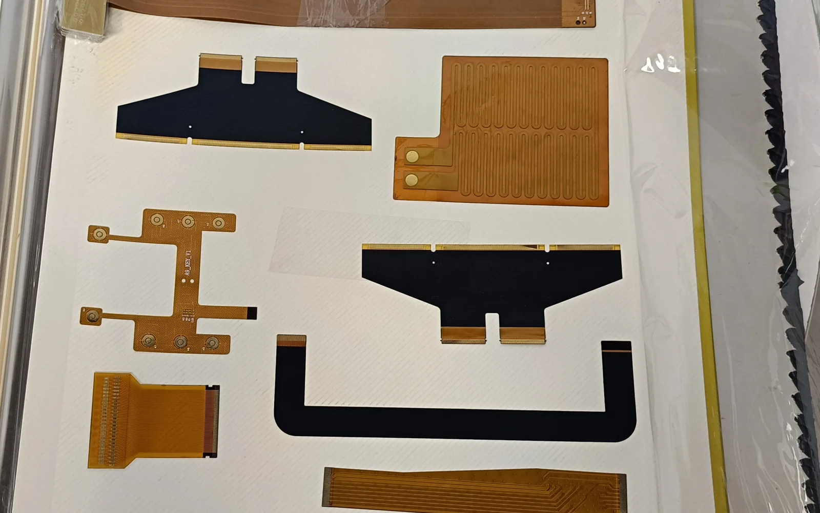
Quick decisions for an industrial HMI hardware architecture
| Project condition | Preferred hardware response | Drawing or validation consequence |
|---|---|---|
| Operators wear gloves, encounter coolant, or clean the panel wet | Compare resistive touch, glove-capable projected capacitive touch, and dedicated keys with actual contaminants | Supply glove type and cleaner list; run wet-touch and false-activation tests |
| The same command must remain available during a display fault | Add a separate hard key, selector or safety-rated device as the risk assessment requires | Define the independent circuit, legend and state indication outside the display UI |
| The unit mounts in a washdown or dusty area | Treat the display, bezel, gasket, cutout and fastener pattern as one sealing system | Specify the installed enclosure target and test the complete mounted assembly |
| Strong glare or oblique viewing is expected | Select the display and bonding method from measured lighting and viewing geometry | Approve optical performance on a mounted prototype, not a loose display sample |
| The controller network is fixed | Lock protocol, physical port, connector orientation, cable exit and service access together | Add interface ownership and a powered communication test to the approval plan |
| Field replacement must be fast | Use accessible fasteners, keyed connectors, defined cable slack and a replaceable gasket strategy | Validate removal and reinstallation with the production tool set |
An OEM can source complete HMI assemblies or integrate separate parts. For foundational terminology, see What Is an HMI Panel? Hardware and OEM Guide.
HMI automation hardware is a layered operator-to-controller interface
An industrial HMI is not simply a touchscreen. NIST defines an HMI as the hardware or software through which an operator interacts with a controller; its OT guidance places HMIs alongside PLC, DCS and SCADA components in a larger system with safety, reliability and security constraints (NIST SP 800-82 Rev. 3). The HMI presents state and accepts intent, while the controller executes machine logic and SCADA may supervise multiple assets. A front-panel manufacturer cannot determine controller-code correctness from a mechanical drawing.
ISA-101 treats hierarchy, navigation, graphics, alarming, security and interfaces as lifecycle decisions (ISA101 scope). Display area, touch type, keys, indicators and service ports therefore follow the operating concept.
ISO 13850 covers machinery emergency-stop principles and points to IEC 60204-1 for electrical/electronic realization (ISO 13850:2015). Do not assume an ordinary HMI touch object replaces that implementation. Risk assessment determines independent devices and the control path.
Start the HMI architecture with operator tasks and failure response
A usable architecture begins with a task inventory: who operates the machine, what they must see or change, how quickly they must respond, and what remains possible after a screen, touch, network or power fault. These inputs matter more than a preferred screen diagonal.
Divide tasks into four groups:
- Observe: state, process value, mode, interlock and progress.
- Act: start a permitted sequence, acknowledge an alarm or change an authorized setting.
- Recover: identify a fault and reach the state defined by the controls and safety design.
- Maintain: connect a service tool, replace the HMI, inspect seals and restore configuration.
Map each task to the consequence of losing the primary display or input. A low-consequence setting may tolerate service-terminal recovery; a required local indication may need a separate lamp; a stop function may require independent hardware. This exposes physical keys, indicators and connectors before bezel design.
The ISA-18 series frames alarm work as a lifecycle from philosophy and rationalization through operation, maintenance and change (ISA-18 series). Reserve display area for alarms and response information, and place annunciation where operators can detect it. Priority and controller behavior remain software responsibilities; hardware must provide room and unambiguous input.
The architecture should expose every physical and responsibility boundary
The following stack separates the operator-facing assembly from control logic and from safety functions. Arrows show information or command flow, not certification ownership.
OPERATOR
   ⇅  sight, touch, gloves, tools, cleaning chemicals
FRONT-PANEL ASSEMBLY
   ├─ protective/graphic surface
   ├─ touch sensor and/or keys, domes, indicators
   ├─ optical bond or controlled air gap
   ├─ display module and backlight
   └─ bezel, gasket, carrier, tails and connectors
   ⇅  display, touch, key, LED and power interfaces
HMI COMPUTE / OPERATOR TERMINAL
   ⇅  Ethernet or serial physical link
PLC / PAC / MOTION CONTROLLER
   ⇅  field input/output, drives, sensors and actuators
MACHINE PROCESS

SEPARATE SAFETY PATH WHEN REQUIRED BY RISK ASSESSMENT
E-stop / guard device → safety logic → final switching element
Architecture diagram: an operator interacts with a layered front-panel assembly, which connects to an HMI compute layer and then to the PLC and machine process; a required safety path remains separate from the ordinary HMI chain.
The diagram clarifies ownership. Industrial design owns reach, viewing and labels. Mechanical engineering owns cutout, stiffness, sealing and thermal path. Electrical engineering owns power, grounding, protection and pinout. Controls engineering owns commands, alarms and fail states. Quality owns evidence and change control; procurement keeps approved parts and supplier documents aligned.
A seven-layer front-panel stack makes HMI hardware manufacturable
A reliable HMI drawing describes seven functional layers and their interfaces, not only the visible face.
| Layer, front to back | Primary decision | Common failure path | Required drawing or evidence |
|---|---|---|---|
| 1. Protective and graphic surface | Polyester, polycarbonate, coated glass or other qualified surface; texture, window and legend system | Abrasion, chemical attack, delamination, unreadable legends | Material/finish, print colors, window limits, cleaner list and cosmetic criteria |
| 2. Touch or discrete input | Resistive, projected capacitive, membrane keys, metal domes, encoders or a hybrid | Missed touch, false touch, glove failure, trapped key, unintended multi-touch | Touch type, glove/contaminant condition, actuation zones and debounce owner |
| 3. Optical interface | Air gap, optical adhesive, anti-glare layer or laminated cover | Reflection, bubble, mura, contamination, stress transfer | Bonded area, adhesive identity, thickness, lamination and optical acceptance criteria |
| 4. Display module | Active area, resolution, brightness class, viewing geometry, backlight and temperature range | Washout, slow response at temperature, backlight degradation, connector damage | Exact part number, active-area datum, keep-outs, power and supplier limits |
| 5. Circuit and indication | Flexible circuit, membrane-switch circuit, PCB, keys, LEDs and shielding | Open trace, short, LED mismatch, tail fatigue, EMC susceptibility | Schematic/pinout, tail bend zone, connector, current limits and electrical test |
| 6. Carrier, bezel and seal | Bezel stiffness, gasket, adhesive land, fastener pattern and compression control | Leak path, glass stress, bezel bow, gasket roll or over-compression | Cutout, flatness, surface finish, torque/compression method and leak-test fixture |
| 7. Rear service interface | HMI compute module, power/network connectors, strain relief and removable cover | Cable pullout, wrong mating connector, inaccessible replacement, exposed port | Connector keying, cable exit, bend radius, access envelope and replacement sequence |
Projected capacitive touch can provide a continuous surface and multi-touch, but its controller, electrodes, grounding, overlay and firmware form one system. Texas Instruments identifies ESD, radiated RF, electrical fast transient/burst and conducted RF as relevant disturbances; its IEC 61000-4-6 discussion covers 150 kHz to 80 MHz (TI TIDUBK4 design guide). Test the final stack with the required gloves, moisture and supply. Resistive touch or keys may better serve deterministic single-point input.
Bonding is an engineering variable. The 3M 8211–8215 optical-adhesive series lists nominal options from 25 to 125 µm for display/touch laminations (3M OCA technical data). The 3M 7966MWS membrane-switch spacer lists 0.23 mm total construction under ASTM D3652 (3M 7966MWS data sheet). Both documents call these typical values, not universal limits. Tolerance the complete stack by exact material and process.
Freeze the PLC interface as hardware even when programming stays separate
The interface boundary must name protocol and physical implementation. “Ethernet” does not define connector retention, shielding or recovery. ODVA defines EtherNet/IP as Common Industrial Protocol over IEEE 802.3 Ethernet and TCP/IP (ODVA EtherNet/IP developer guide). Draw the exact port, cable route and strain relief.
Use an interface control table before releasing the enclosure:
| Interface | Hardware team freezes | Controls/integrator freezes | Joint approval evidence |
|---|---|---|---|
| Display | Connector, voltage rails, backlight path, mechanical datum | Resolution, orientation, rendering and boot behavior | Powered image, cold/warm start and fault-state review |
| Touch / keys | Sensor type, tail, controller, shielding, key matrix and connector | Calibration, gesture policy, debounce and command mapping | Input map tested with required gloves and contaminants |
| PLC network | Physical port, cable, shield/ground approach and access | Protocol, addressing, tags, update behavior and timeout state | Communication recovery and cable-disconnect test |
| Service port | Connector, cover, physical access and labeling | Authentication, allowed tools, logging and disable policy | Authorized-service workflow and closed-cover inspection |
| Power | Input connector, polarity protection and consumption envelope | Startup/shutdown sequence and fault handling | Brownout, restart and wrong-connection prevention checks |
See PLC and HMI Integration: Hardware, Signals and Interfaces and Industrial HMI Communication Protocols and Hardware Interfaces for complementary boundaries. Protocol configuration remains outside front-panel manufacturing scope.
Enclosure design and maintainability determine the installed rating
A rated component can still fail as an installed panel if the cutout, gasket, clamp, cable entry or cover breaks the protection system. IEC 60529 classifies degrees of enclosure protection (IEC 60529 scope); NEMA 250 defines North American enclosure types and exclusions (NEMA 250 scope). Specify the installed condition and avoid casual IP-to-NEMA equivalence.
Rockwell’s January 2025 PanelView 5510 data illustrates the dependency. Covered variants list 0–55 °C operation and 5–95% relative humidity without condensation. Listed resistive/stainless terminals require 1.5–4.8 mm mounting panels; listed capacitive models call for 3–6 mm plus surface limits, and front ratings differ (PanelView 5510 technical data). These are product examples, not custom-HMI targets.
For service, provide rear access without disturbing unrelated wiring, enough cable slack to support the unit, keyed connectors, and a defined gasket replacement policy. Record installation tools, fastener sequence and compression control. A flush face that requires dismantling half the cabinet is a service failure.
Grounding crosses the mechanical/electrical boundary. Rockwell publication 1770-4.1 includes operator terminals and displays while covering raceways, bonding, grounding and transient suppression (industrial automation wiring and grounding guidance). Reconcile it with equipment instructions and electrical code.
Validation must reproduce the installed HMI, not an isolated component
Test the assembled front panel under defined conditions. IEC 60068-1 frames environmental test methods and severity tailoring (IEC 60068-1). IEC 61000-6-2 is a generic industrial immunity standard when no dedicated product or product-family standard applies (IEC 61000-6-2). The compliance owner must select applicable severities; a citation is not a test plan.
| Failure path | Test input and setup | Observe during test | Approval evidence |
|---|---|---|---|
| Water or dust enters at an interface | Production enclosure, cutout, fasteners, cables and installed ingress method | Ingress, touch/display operation and seal movement | Report with specimen revision, mounting, method and result |
| Cleaner attacks surface or adhesive | Named chemical, concentration, temperature, dwell/wipe cycle and drying | Color/gloss change, swelling, cracking, lift and legibility | Before/after record and material traceability |
| Touch fails with gloves or contaminant | Final stack, settings, required glove and contaminant | Missed/false touches, multi-touch and recovery | Input matrix by zone and condition |
| Display degrades with environment | Powered assembly at defined hot, cold and humidity conditions | Image, backlight, touch, boot and optical defects | Limits, stabilization time and criteria |
| EMC causes false command or reset | Final cables, grounding, supply, enclosure and applicable setup | False input, upset, reset, link loss and recovery | Lab report tied to hardware/firmware revision |
| Vibration/shock damages the assembly | Production mount, fasteners, cable mass, axes and severity | Movement, intermittency, display damage and seal shift | Pre/post function and inspection record |
| Panel fit distorts the stack | Worst-case cutout, thickness, flatness and fastening | Bow, touch drift, glass stress and compression | Dimensional report and mounted approval |
| Service creates a leak or wiring error | Production tools, parts and work instruction | Access, connector errors, gasket damage and function | Replacement trial and required repeat checks |
Link the matrix to testing and validation planning. During prototyping and sample approval, use production-intent materials, the enclosure and the real controller or a controlled simulator. A loose sample cannot approve the installed seal, grounding or service procedure.
For U.S. projects, UL describes UL 508A as the industrial-control-panel standard (UL 508A summary). A recognized or rated component does not establish the status of the completed panel or machine.
Use a gated OEM design flow and release complete RFQ inputs
Use six gates before release:
- Define tasks: gloves, reach, viewing, cleaning, authorization, alarms and degraded operation.
- Draw ownership: front panel, HMI compute, PLC/network, SCADA and safety functions.
- Select input/display: compare touch, keys, indicators, size and bonding in the real environment.
- Freeze interfaces: datums, cutout, stack, seal, panel limits, tails, pinout, cables and service envelope.
- Test a mounted prototype: optical, input, ingress, environmental, EMC, mechanical and replacement conditions.
- Control production: align drawings, bill of materials, firmware/calibration dependencies, inspection and changes.
A separate HMI Panel Assembly Design Checklist can support the drawing release. For a supplier review, provide:
- display part number, active area, size and orientation;
- front-panel drawing with cutout, thickness, flatness, finish and clearance;
- overlay, touch, optical, display, circuit, carrier, bezel and gasket stack;
- power, display, input, network and service interfaces with connector/pinout ownership;
- operating, cleaning, glove, contaminant, lighting, mechanical and ingress conditions;
- test methods, severities, acceptance criteria and evidence format;
- prototype stages, annual volume and change control.
Send the package through send drawings for engineering review before tooling or enclosure release.
The same architecture scales across machines, but not every application fits it
Packaging-machine HMIs may use a small local display and direct PLC link. An HMI for CNC machines needs dense status, input compatible with coolant/chips, deliberate mode controls and protected service access. Process skids may emphasize alarms and enclosure compatibility. Industry 4.0 ports add access and lifecycle ownership; ISA/IEC 62443 treats IACS security as shared work across owners, suppliers, integrators and service providers (ISA/IEC 62443 overview).
Custom architecture is unnecessary when a fixed-function device needs one indicator and command, or a standard terminal meets all mechanical and lifecycle needs. It is unsuitable for a safety function that requires a separately engineered safety-rated chain. Custom hardware should solve a task, packaging or environmental constraint.
Frequently asked questions
What does HMI automation mean in an industrial machine?
HMI automation is the operator-facing part of a machine or process. It presents status, alarms and permitted controls; the PLC executes control logic. The hardware architecture includes the display, input technology, front surface, circuits, compute interface, connectors, seals, mounting and service provisions.
What is the difference between an HMI and a PLC?
An HMI presents machine information and accepts authorized input. A PLC reads field signals, executes logic and drives outputs. They exchange data but keep different responsibilities. Losing the HMI should not redefine the PLC’s safe state, interlocks or independent safety functions.
Which touch technology is best for an industrial HMI?
No touch technology is best without operating conditions. Projected capacitive touch suits continuous, gesture-capable interfaces when tuned for gloves, moisture and EMC. Resistive touch can suit deterministic single-point input with certain gloves. Discrete keys fit tactile location, degraded-display operation or dedicated commands.
Does an IP65-rated display make the complete HMI panel IP65?
No. Installed protection depends on the component, bezel, gasket, cutout, panel surface, fasteners, cable entries and installation. Verify a production-representative assembly in its enclosure. Do not infer a NEMA type from an IP code without checking separate requirements and end conditions.
Can an HMI touchscreen replace an emergency-stop button?
An ordinary touchscreen should not be assumed to replace an emergency-stop device. The risk assessment and applicable standards determine the function, device and control path. A safety-related electronic interface requires an appropriate safety architecture, components, validation and ownership beyond normal HMI hardware.
What should an OEM send for an HMI assembly RFQ?
Send the display size and part number, dimensioned front-panel drawing, interface stack, connector/pinout, enclosure and service constraints, environment, cleaning conditions, validation requirements, prototype stages and annual volume. Identify ownership of display drive, touch tuning, PLC communication, firmware and compliance evidence.
How should an HMI for CNC machines differ from a generic touchscreen?
Specify an HMI for CNC machines around coolant/chip exposure, gloves, mode selection, dense status, vibration, cleaning and access. Dedicated keys or selectors may suit frequent or consequence-bearing actions. Validate the mounted assembly with its enclosure, cables and controller interface.
How does Industry 4.0 change HMI hardware architecture?
Industry 4.0 connectivity can add upstream Ethernet, remote service, gateways or compute interfaces. It does not move deterministic control into the front overlay. New ports create network, access, update and recovery ownership that the OEM, integrator and asset owner must assign before enclosure release.
Project handoff
For an engineering review, provide the display size, front-panel drawing, interface stack, environment and annual volume. JASPER can review the manufacturable front-panel assembly boundary—display, touch, overlay, circuit, bonding, gasket, connector and enclosure interfaces—while the OEM or controls integrator retains PLC/SCADA programming and machine-level validation responsibility. When the requirements are ready, request an engineering quote.
References
- National Institute of Standards and Technology, Guide to Operational Technology (OT) Security, NIST SP 800-82 Rev. 3, 2023.
- International Society of Automation, ISA101, Human-Machine Interfaces.
- International Society of Automation, ISA-18 Series of Standards.
- International Organization for Standardization, ISO 13850:2015 — Safety of machinery — Emergency stop function — Principles for design.
- International Electrotechnical Commission, IEC 60529 — Degrees of protection provided by enclosures (IP Code).
- National Electrical Manufacturers Association, NEMA 250-2018 — Enclosures for Electrical Equipment (1000 Volts Maximum), Contents and Scope.
- Rockwell Automation, PanelView 5510 Terminals Specifications Technical Data, 2715P-TD001F-EN-P, January 2025.
- Rockwell Automation, Industrial Automation Wiring and Grounding Guidelines, publication 1770-4.1, February 1998.
- Texas Instruments, Noise-Tolerant Capacitive-Touch Human-Machine Interfaces Design Guide, TIDUBK4, June 2016.
- 3M, 3M Optically Clear Adhesives 8211, 8212, 8213, 8214 and 8215 Technical Data, January 2010.
- 3M, 3M Membrane Switch White Spacer 7966MWS Technical Data Sheet, revision February 2026.
- ODVA, EtherNet/IP Quick Start for Vendors Handbook, PUB00213R0, 2008.
- International Electrotechnical Commission, IEC 61000-6-2:2016 — EMC immunity standard for industrial environments.
- International Electrotechnical Commission, IEC 60068-1:2013 — Environmental testing, Part 1: General and guidance.
- UL Solutions, UL 508A Third Edition Summary of Requirements.
- International Society of Automation, ISA/IEC 62443 Series of Standards.
Bring the drawing, stack and operating conditions
JASPER engineering will review the interfaces, open risks and evidence required for a production quote.