
PLC and HMI integration is the engineered boundary between the controller that executes machine logic and the operator hardware that displays state and returns supervisory commands. For an OEM, a shared protocol is necessary but not sufficient. The design must freeze exact device models, power, electrical layer, driver and data map, connectors, grounding and isolation, display/touch stack, mounting seal, environment, and validation owner. Treat custom HMI assemblies as documented, replaceable hardware subsystems. Choose a combined PLC-HMI only when its smaller footprint outweighs the coupled service life, thermal load, and replacement path.
| Quick decision | Recommended engineering position | Evidence to release |
|---|---|---|
| PLC versus HMI role | Keep machine control and interlocks in the controller architecture; use the HMI for visualization and authorized operator requests | Functional block diagram and responsibility matrix |
| Communication | Qualify the protocol, driver, data model, physical medium, connector, and network settings as one interface | Exact catalog numbers, firmware, pinout, cable specification, and working communication file |
| Power and isolation | Size from the selected hardware's voltage range, inrush, steady load, grounding scheme, and required isolation barrier | Power budget, schematic, protective-device selection, and isolation definition |
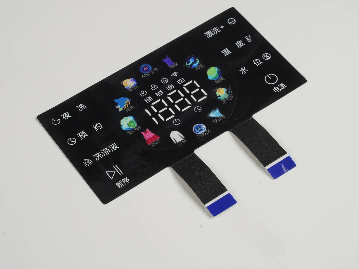
| Front-panel hardware | Validate display, touch, overlay or cover lens, bond, gasket, cutout, support frame, and cable exits as an assembly | Released stack drawing, tolerances, material callouts, and golden sample |
| Environment | Assign ingress, EMC, temperature, humidity, shock, vibration, chemicals, and cleaning conditions to the mounted product | Test plan with conditions, severities, orientations, acceptance limits, and reports |
| Commissioning | Test normal operation and controlled faults across power, link, data, touch, and reboot states | Signed validation matrix, issue log, configuration archive, and approved sample |
A PLC controls the process; an HMI presents and requests information
The PLC and HMI have different jobs even when they share a housing. A programmable logic controller reads field inputs, executes control logic, writes outputs, and exposes selected state. A human-machine interface displays that state and converts permitted touches, key presses, or entries into requests for the controller to evaluate.
IEC 61131-2:2017 covers requirements and tests for programmable controllers and associated industrial-control peripherals; the system designer must still define the interface. The foundational What Is an HMI Panel? Hardware and OEM Guide explains the operator-panel hardware context.
| Layer | Primary job | Boundary owner |
|---|---|---|
| Field devices | Sense or act on the process | Machine and controls engineering |
| PLC / controller | Execute control, approved safety architecture, and field input/output | Controls and safety engineering |
| HMI | Present controller state and send authorized operator requests | HMI application owner and hardware integrator |
| SCADA / supervisory system | Aggregate plant or multi-machine data | Plant OT or system integrator |
Local input/output, soft-controller, and combo products change the packaging, not the need to allocate control, safety, visualization, networking, and maintenance ownership.
The PLC-HMI boundary includes seven hardware and data layers
A complete PLC-HMI interface runs from controller memory to the operator's finger. A protocol name covers only part of that path. Release every layer below, including power and mounting boundaries.
PROCESS SIDE                                              OPERATOR SIDE

Sensors / actuators
        │ field wiring or field network
        ▼
PLC input/output ──► control + safety logic ──► exposed data / commands
                                           │
                              driver + protocol + data map
                                           │
                 cable ─ connector ─ transceiver / isolation
                                           │
                              HMI processor + application
                                           │
                        display interface + touch controller
                                           │
                    LCD ─ touch sensor ─ lens/overlay ─ operator

PLC supply / PE ───────────────── system bonding plan ── HMI supply / chassis
Enclosure interior ───────── gasket + cutout boundary ── exposed front face
Controls engineering owns controller compatibility, tag behavior, communication roles, and recovery. The HMI integrator owns the display/touch stack, internal circuits, cables, and assembly. The enclosure owner controls the cutout, mounting surface, external routing, and final ingress claim; the machine OEM approves the system. A deeper component map is available in HMI Hardware Architecture for Industrial Automation.
PLC and HMI communication requires a protocol, physical layer, and data contract
PLC and HMI communication requires agreement on the driver, role, medium, connector, pinout, addressing, data type, timing, and security. Ports are not protocols. Matching RJ45 sockets prove mechanical compatibility, not interoperability.
| Interface family | What the named technology defines | Common physical implementation | Hardware decisions to freeze | Commissioning proof |
|---|---|---|---|---|
| Modbus serial / RTU | Modbus semantics over a serial implementation | Often RS-485 | Topology, polarity, reference, shield, termination, bias, baud, parity, address | Read/write, scaling, word order, timeout, recovery |
| Modbus TCP | Modbus messages over TCP/IP | Copper or fiber Ethernet | Device capability, connector, switch, cable environment, IP plan | Load, address conflict, cable loss, restart |
| EtherNet/IP | CIP over Ethernet and TCP/IP | Device-supported industrial Ethernet | ODVA profile, topology, switch, connector, cable, grounding | Identity, connection, data, counters, disconnect |
| PROFINET | Industrial Ethernet profiles and device behavior | Device- and class-dependent Ethernet | Device support, port, topology, installation class, naming/IP method | Identification, topology, diagnostics, recovery |
| OPC UA | Information, message, communication, and conformance models | Deployment-selected transport, often Ethernet | Profile, role, endpoint, certificates, time, media, resource limits | Trusted session, mapping, subscriptions, renewal, recovery |
The Modbus Application Protocol does not select a connector, cable, transceiver, or isolation circuit. ODVA defines EtherNet/IP as CIP on Ethernet but treats media planning and verification separately. PI separates PROFINET design, assembly, and commissioning. The OPC UA overview separates information and communication models from deployment-specific transport.
Media and network policy remain separate. ODVA Pub 148 applies a 100 m (328 ft) channel-planning limit to covered copper Ethernet cases; the selected device, media, and environment still govern. The National Institute of Standards and Technology's 2023 OT guide recommends segmenting and isolating IT/OT devices by trust, criticality, data flow, or location. OPC Foundation's 2025 Part 1 likewise separates the communication model from deployment media.
For deeper protocol selection, use Industrial HMI Communication Protocols and Hardware Interfaces. Procurement should require exact device and firmware identifiers, installed options, approved driver, and cable drawing. “Supports Ethernet” or “supports Modbus” is not a compatibility statement.
Power, grounding, and isolation must be defined as circuits, not labels
An HMI power entry needs a voltage window, steady and peak load, startup behavior, protection, polarity, bonding, conductor, and connector requirements. Rockwell Automation's April 2024 data, for example, specifies 24 V DC nominal and 18–30 V DC for listed PanelView Plus 7 Performance DC models, with model-dependent power. Those values apply only to the cited catalog numbers and revision.
Distinguish protective earth or chassis, DC return, signal reference, and shield on the drawing. Name the bond points and shield termination; an undocumented connection can route noise through communication or touch/display circuits.
Define isolation by barrier location, working voltage, transient, insulation type, creepage, clearance, pollution environment, altitude, and isolated-power need. IEC 60664-1:2020, amended in 2025, addresses insulation coordination up to AC 1,000 V or DC 1,500 V. A transceiver part number alone does not qualify the assembly.
For RS-485, Texas Instruments' RS-485 Design Guide shows isolation preventing current between remote grounds. Analog Devices' AN-960 places parallel termination at line ends, matched to cable impedance. Verify the actual topology, cable, baud rate, routing, and noise conditions.
Display and touch choices are part of the electrical interface
The visible HMI is a tolerance and signal stack, not a screen diagonal. A build may include a cover lens or overlay, adhesive, touch sensor, display, support frame, gasket, controller, flex circuits, and restraints. The drawing must align the cutout, printed mask, touch area, display area, viewing cone, and mounting features.
Resistive touch suits pressure input from a gloved finger or passive stylus. Projected-capacitive touch supports gestures and a continuous front, but glove thickness, water, cover and bond thickness, sensor geometry, tuning, display noise, and grounding affect performance. Microchip's maXTouch Sensor Design Guide documents sensor choices and display-noise interactions; it does not create a universal glove or water claim.
The hardware specification should name these operating inputs:
- glove, water, stylus, simultaneous-touch, and palm-rejection conditions;
- cleaning agents, dwell, wipe method, and cosmetic acceptance;
- ambient illumination, viewing angle, color/contrast, and backlight control;
- display temperature and touch/display electrical interfaces, pinout, cable, and orientation.
Freeze these inputs before tooling. The HMI Panel Assembly Design Checklist carries active-area, bezel, adhesive, gasket, graphic, flex, connector, and enclosure decisions into review.
Connectors and enclosure details determine serviceability and ingress
Connector location controls the requirement. An internal RJ45, exposed locking Ethernet connector, pluggable power terminal, and internal FFC face different loads. Specify mate, keying, pin numbers, retention, shield path, cable exit, bend/service loop, strain relief, insertion access, and replacement clearance.
Do not assign an IP code to an overlay, gasket, or connector unless the claim is bounded to that component. IEC 60529 classifies enclosure protection. The final claim identifies assembly, side, mounting, and test. Siemens Comfort Panel instructions illustrate the boundary: IP65 at the mounted front, IP20 at the rear, with the front rating dependent on a flush seal. The result is model-specific.
Gasket land, compression, cutout edge, flatness, clamp load, coating, glands, and enclosure seams control the installed result. Derive values from the selected material system and verified assembly. Provide tool access and a service path that does not require peeling a bonded display from the panel.
PLC-HMI ownership should be explicit before prototype release
Assign every interface to one accountable owner and approval record. Name every owner.
| Deliverable | Controls / software owner | HMI hardware integrator | Enclosure / machine OEM | Quality / commissioning |
|---|---|---|---|---|
| Compatibility | Select devices, firmware, driver, roles, and data contract | Confirm board and port implementation | Approve architecture and service strategy | Archive the working baseline |
| Power / grounding | Define supply and bonds | Design entry, protection, distribution, chassis | Provide supply, PE, routing, protection | Test limits, startup, interruption, thermal state |
| Display / touch | Define operator functions | Own stack, controller, flex, drawings | Approve aperture, cleaning, service | Approve samples under stated conditions |
| Cutout / sealing | Supply cabinet keep-outs | Define bezel/gasket interface | Own cutout, surface, clamps, glands, final claim | Inspect and run ingress plan |
| Safety | Define qualified architecture | Avoid unsupported hardware assumptions | Own risk assessment and acceptance | Validate the safety plan |
| Recovery | Archive projects, certificates, addresses | Supply hardware revision and service details | Define replacement access | Run faults and sign evidence |
Do not treat an ordinary HMI command as a safety function. ISO 13849-1:2023 covers safety-related control-system parts; IEC 62061:2021 covers machinery safety-control design, integration, and validation. A safety-related operator action belongs in the machine owner's qualified architecture.
Commissioning must test normal states, faults, and the mounted assembly
PLC-HMI commissioning starts from a released interface matrix. A golden configuration proves one combination; validation must also exercise environmental and fault conditions.
| Validation area | Inputs and conditions | Required observations | Release evidence |
|---|---|---|---|
| Pre-power | BOM, pinout, polarity, PE/chassis, shield, termination, route, strain relief | Drawing match; specified continuity/isolation | Inspection and marked schematic |
| Power | Specified input limits, startup, interruption, load switching, ambient | Current, reset, display, settings, recovery | Instrumented test log |
| Communication | Approved firmware/driver, load, reconnect, network/serial fault | Link, errors, freshness, timeout, reconnection, no unintended command | Configuration and communication log |
| Data | Read/write items, types, scaling, limits, word order, stale data | Correct value, bounded entry, acknowledgment, bad-quality state | Signed tag/register list |
| Touch / display | Glove, water, light, target, edge, temperature | Detection/rejection, visibility, alignment, no false input | Stack-specific approval report |
| Mechanical / ingress | Production cutout, gasket, clamps, cables, process | Alignment, retention, post-test function, ingress result | Dimensional, assembly, and test reports |
| EMC / environment | Applicable scope, ports, modes, axes, severities, monitoring | Functional criteria, emissions, mechanical condition | Lab report tied to sample/configuration |
| Service | Replacement, reboots, restore, certificate/address update | Controlled return without hidden edits | Maintenance and recovery record |
IEC 61000-6-2:2016 and IEC 61000-6-4:2018 provide generic industrial EMC scopes when no relevant product-family standard applies. IEC 60068-2-6:2007 and IEC 60068-2-27:2008 provide vibration and shock methods; the product requirement still defines mounting, axes, severities, duration, mode, and acceptance. Put those conditions into testing and validation planning and production-intent prototyping and sample approval.
Route faults by signature. Link without data points to driver, role, address, security, or mapping. Serial errors point to polarity, reference, topology, termination, bias, shield, route, or ground potential. False touch points to stack, tuning, display noise, ground, water, or cable strain. Reset/flicker requires power, transient, connector, thermal, and EMC measurements. Ingress starts with the complete cutout-gasket-enclosure process.
A PLC-HMI combo is suitable only when coupled lifecycle risk is acceptable
A PLC-HMI combo reduces area, wiring, and part count, but couples controller availability, panel damage, thermal behavior, tools, and replacement. Separate units are easier to scale or replace independently but add ports, cables, space, and integration.
| Architecture | Best fit | Main tradeoff | Hardware review focus |
|---|---|---|---|
| Integrated PLC-HMI | Compact, stable machine with limited input/output and controlled lifecycle | One event can affect control and interface | Thermal path, expansion, safety, restore, replacement |
| Separate PLC and catalog HMI | Machines needing independent controller/panel service or broader controller choice | More devices, wiring, network configuration, and panel space | Port compatibility, cable route, power budget, cutouts, spares |
| Separate PLC and custom HMI assembly | OEM product needing a differentiated front panel, display/touch stack, or enclosure fit | Higher up-front interface and validation discipline | All seven layers in this guide, plus controlled drawings and sample approval |
Compare expected revisions, spares, field skills, safety allocation, exposure, and enclosure constraints before choosing a PLC with HMI combination.
Project inputs required for an HMI hardware review
Send one controlled package with these minimum inputs:
- exact PLC, communication module, HMI processor/runtime, and firmware identifiers;
- protocol, role, driver, topology, address plan, tag/register list, update and timeout behavior;
- supply, power, PE/chassis/shield, isolation, and protection;
- display size/area, interface, readability, and temperature;
- touch, glove/water/stylus, cover/overlay, graphics, and cleaners;
- panel drawing, cutout, datums, tolerances, gasket, mounting, keep-outs, and service access;
- connectors/mates, pinout, cable length/exit, strain relief, and ingress location;
- test specification, modes, severities, criteria, records, prototype plan, annual volume, and revision control.
Use the package to send drawings for engineering review. JASPER can review display size, panel drawing, interface stack, environment, and annual volume for the manufacturable HMI boundary. Controls, SCADA, and safety work remain with system owners. With inputs frozen, request an engineering quote.
Frequently Asked Questions
What is HMI in a PLC system?
An HMI is the operator-facing hardware and application that reads selected PLC data, displays machine state, and sends authorized operator requests back to the controller. The PLC still owns machine logic and field outputs. In a production design, the HMI also includes a power, communication, display, touch, mounting, and environmental interface.
What is the difference between a PLC and an HMI?
A PLC executes control logic from field inputs and commands outputs; an HMI presents controller data and collects operator intent. A PLC can run without a local HMI when the machine design permits it. An HMI normally needs a controller or other data source, even when both runtimes are packaged in one unit.
How do a PLC and HMI communicate?
A PLC and HMI communicate through a supported driver and protocol over a defined physical link, commonly industrial Ethernet or RS-485. Both sides must match roles, addressing, data types, timing, security settings, cable, connector, and pinout. A shared protocol name or matching port alone does not prove interoperability.
Can one HMI communicate with more than one PLC?
One HMI can communicate with multiple PLCs only when its runtime, drivers, connection resources, network architecture, and performance limits support the exact controllers. Define behavior when one controller is offline, keep data sources unmistakable on screen, and test update load, timeout indication, startup order, and partial-network recovery before release.
When should a PLC-HMI link use RS-485 instead of Ethernet?
RS-485 can fit a simple serial or legacy link when both devices support the same protocol and the topology, baud rate, termination, grounding, isolation, and cable environment are controlled. Ethernet fits higher connection density and standard network tooling. Select from device support and lifecycle needs, not a universal distance or speed rule.
Does a PLC-HMI connection need galvanic isolation?
Isolation is required when the system risk assessment identifies ground-potential differences, transients, noise paths, or safety insulation needs that the non-isolated ports cannot tolerate. Specify the barrier location, working voltage, transient environment, insulation type, creepage, clearance, altitude, and isolated power. “Isolated” without those conditions is incomplete.
Is a PLC-HMI combo better than separate units?
A PLC-HMI combo is better when compact packaging and reduced external wiring outweigh coupled failure, obsolescence, thermal, software-tool, and replacement risks. Separate units suit machines that need independent upgrades, broader controller choice, or simpler field replacement. Compare lifecycle and service strategy before comparing enclosure area or purchase price.
What should an OEM send to an HMI hardware supplier?
Send exact device and firmware identifiers, protocol and pinout, power and grounding data, display size, touch requirements, the front-panel drawing, stack and connector details, environment and test criteria, approval process, and annual volume. Include controlled CAD/PDF revisions and name the owner of PLC programming, enclosure compliance, safety validation, and final commissioning.
References
- International Electrotechnical Commission, IEC 61131-2:2017 — Equipment requirements and tests.
- International Electrotechnical Commission, IEC 60529 consolidated version — Degrees of protection provided by enclosures.
- International Electrotechnical Commission, IEC 61000-6-2:2016 — Immunity standard for industrial environments.
- International Electrotechnical Commission, IEC 61000-6-4:2018 — Emission standard for industrial environments.
- International Electrotechnical Commission, IEC 60068-2-6:2007 — Sinusoidal vibration.
- International Electrotechnical Commission, IEC 60068-2-27:2008 — Shock.
- International Electrotechnical Commission, IEC 60664-1:2020 — Insulation coordination.
- Modbus Organization, MODBUS Application Protocol Specification V1.1b3, 2012.
- ODVA, EtherNet/IP Media Planning and Installation Manual, Pub 148.
- PROFIBUS & PROFINET International, PROFINET Installation Guidelines, design guide v1.59, 2025.
- OPC Foundation, OPC UA Part 1: Overview and Concepts, v1.05.06, 2025.
- National Institute of Standards and Technology, NIST SP 800-82 Rev. 3 — Guide to OT Security.
- Texas Instruments, The RS-485 Design Guide, SLLA272D.
- Analog Devices, AN-960 — RS-485/RS-422 Circuit Implementation Guide.
- Siemens, S7-1200 G2 HMI-to-PLC communication.
- Rockwell Automation, PanelView Plus 7 Performance Terminals Technical Data, 2711P-TD009M-EN-P.
- Siemens, SIMATIC HMI Comfort Panels Operating Instructions.
- Microchip Technology, AN3908 / QTAN0080 — maXTouch Sensor Design Guide.
- International Organization for Standardization, ISO 13849-1:2023 — Safety-related parts of control systems.
- International Electrotechnical Commission, IEC 62061:2021 — Functional safety of safety-related control systems.
Bring the drawing, stack and operating conditions
JASPER engineering will review the interfaces, open risks and evidence required for a production quote.