
Seat sensor connector design must be released with the pressure-mat tail, seat-motion envelope, frame route, keyed interface, strain relief, assembly sequence, and service loop—not selected as an isolated plug. This guide helps seat, harness, manufacturing, quality, and sourcing teams turn those interfaces into one drawing and validation package. It does not establish restraint-system or vehicle-level compliance.
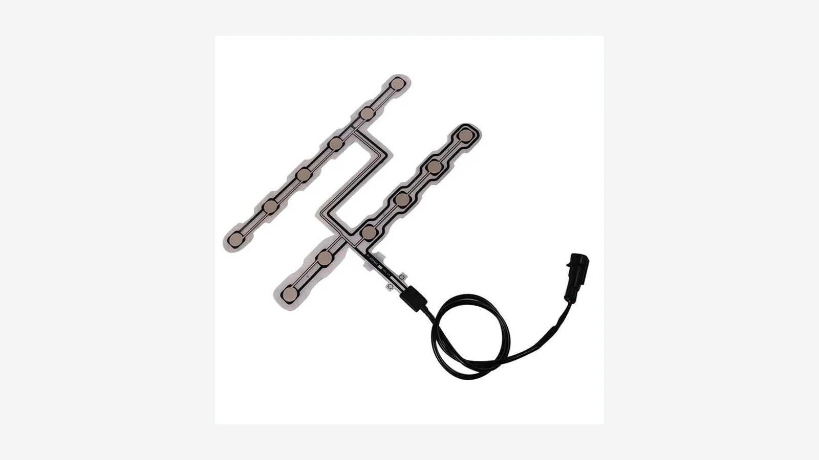
A flexible membrane seat pressure sensor can work correctly on a bench and still fail after installation if its pigtail is trapped, pulled around a frame rail, folded at a termination, or left to load the connector through seat travel. Freeze the route before tooling. The useful release package includes the seat frame, cushion and suspension, full travel envelope, trim attachments, selected connector drawing, mating harness, clip locations, assembly order, service position, and acceptance plan.
1. Why the Connector, Tail, and Harness Fail as One System
Under-seat wiring occupies a moving mechanical space. Cushion foam deflects under an occupant; suspension elements move; powered tracks translate; height and recline mechanisms sweep different volumes; trim workers install hog rings or clips; and service technicians need enough access to disconnect the assembly. A connector that meets its own catalog specification can still be loaded by the route around it.
General Motors documented that chain in Service Bulletin 17-NA-010, dated December 2017. On the named Chevrolet Impala applications, the Passenger Presence System mat pigtail could be trapped above the seat suspension or routed tightly around the frame. Seat use then placed strain on the PPS X2 connection, which could loosen or disengage. GM’s corrective instruction was not simply “replace the connector”: inspect the route and let the pigtail move freely with cushion motion while minimizing stress on the electrical connection.
A second General Motors record, Bulletin 16-NA-145, documents a different assembly path. A passenger-presence sensor tail could be pinched during trim hog-ringing; repeated ingress, egress, and knee loading at the crease could then create an open or high-resistance printed circuit. The two bulletins are platform-specific, but together they establish a useful design principle: printed conductors, terminations, clips, trim operations, seat motion, and the connector must be reviewed in the installed seat.
Failure chain from route error to symptom
| Route or assembly error | Local mechanical condition | Plausible damage path | Observable symptom | Inspection focus |
|---|---|---|---|---|
| Pigtail trapped above suspension | Cushion motion pulls a restrained lead | Terminal load, connection loosening, conductor fatigue | Intermittent or open sensor signal | Route through suspension at loaded and unloaded cushion positions |
| Lead wrapped tightly around frame | Seat/cushion movement transfers tension to the interface | Connector unseating, terminal fretting, insulation damage | Movement-dependent fault | Minimum slack and edge clearance across all seat positions |
| Printed tail pinched by hog ring or trim attachment | Repeated load acts at a fixed crease | Printed conductor cracking or rising resistance | Open or high-resistance circuit | Trim-installation sequence and every attachment point |
| Bend starts at tail termination | Stiffness changes abruptly beside the electrical joint | Trace or coverlay damage; termination peel | Early assembly failure or later intermittency | Straight transition and no-bend zone |
| Connector is inaccessible after trim | Blind insertion or forced service angle | Partial mating, lock damage, repeated rework | Failed end-of-line check or service damage | Hand/tool envelope and positive lock verification |
| Excess loop reaches a track or spring | Uncontrolled slack becomes a moving snag | Abrasion, crushing, cut insulation, pulled clip | Short, open, or sporadic signal | Swept-volume check through travel, recline, height, and cushion deflection |
This table is a diagnostic map, not a universal failure-rate model. A released design still needs its own connector drawing, route tolerances, seat movement, electrical fault criteria, and validation evidence.
2. Define the Route Zones and Interface Owners
SENSOR / CUSHION SIDE VEHICLE SIDE
pressure-mat body
tail root and laminate exit Owner: sensor supplier + seat engineer
straight transition / no-bend zone
controlled free-bend zone
tail-to-wire termination (if used) Owner: named drawing and process owner
sensor-side keyed connector
↕ mating pair / lock / seal Owner: connection-system release owner
first harness anchor
controlled motion or service loop Owner: seat + harness engineers
clips through seat frame
seat-track / recline keep-out
seat or floor mating connector Owner: vehicle harness team
The ownership column is not administrative decoration. It decides who controls the tail stack, terminal application, crimp tooling, connector key, clip, vehicle mating half, diagnostic circuit, change notice, and validation report. A drawing that labels the whole chain “sensor cable” hides these boundaries.
Pressure mat tail routing should be reviewed against the same cushion and frame inputs used for seat pressure sensor placement. Moving the sensing zone can move the tail root. Changing foam channels, suspension wires, heater layers, trim seams, or hog-ring locations can invalidate a previously acceptable route without changing the connector part number.
3. Eight Seat Sensor Connector Design Criteria
The following eight criteria are ordered by the mechanical path from the pressure mat to the vehicle harness. Each criterion should be closed with a drawing, supplier document, physical mock-up, or test record. A verbal statement such as “standard automotive connector” is not release evidence.
3.1 Put the Tail Exit and Bend in Separate, Controlled Zones
The tail root is the laminated boundary where the flexible circuit leaves the sensor body. It should not double as the first bend, restraint, trim-attachment point, or connector support. Locate a straight transition after the root, then place the controlled bend in a free span where its inside radius and direction can be measured in the installed seat.
initial ENGINEERING BENCHMARK — confirm before release. NOT A JASPER SPECIFICATION OR TEST RESULT. For static drafting only, use 2.5 mm (0.10 in) as the minimum inside radius for a printed PET/silver tail. Epec, NFI, and Design Mark publish approximately 0.100 in for static membrane-switch tail routing. For a defined one- or two-layer copper/polyimide tail bent no more than 90°, use R ≥ 12t, where t is the finished flexible stack in the bend zone. This sits in the mid-to-upper portion of published All Flex, Würth Elektronik, and Minco guidance. A stricter supplier rule controls.
Neither value applies to a crease, laminate root, stiffener edge, connector entry, shielded or multilayer flex, recurring motion, or undefined stack. IPC-2223 flex-board practice is relevant only when the construction and contract invoke it; a screen-printed PET pressure mat is not automatically an IPC flexible printed board.
the drawing dimensions the tail root, straight transition, bend center, inside radius, angle, circuit face, no-bend limits, and finished stack from seat or cushion datums.
a leader says “bend as required,” or the installed tail folds at the sensor body, termination, connector, or edge of local reinforcement.
3.2 Classify Every Movement Before Calling the Route Static
A tail may flex during sensor production, cushion trim, seat assembly, connector mating, powered travel, height adjustment, recline, ingress/egress, vibration, crash-service work, and seat removal. These events have different angles, loads, counts, temperatures, and restraints. List them separately.
A flex-to-install route bends during assembly and remains supported. A service bend moves during planned access or replacement. Vibration-driven flex is small recurring movement in an apparently fixed span. Dynamic flex repeats during normal operation. All Flex Solutions and Minco publish construction-specific guidance that distinguishes static installation from repeated flexing; their ratios are starting points, not transferred life ratings.
| Movement class | Required project input | Design consequence |
|---|---|---|
| Cushion deflection | Loaded/unloaded foam and suspension positions | Pigtail must follow cushion motion without pulling the connection |
| Powered track travel | Fore/aft extremes and intermediate interference | Harness loop must clear tracks, motors, screws, and floor attachments |
| Height/recline adjustment | Combined worst-case positions | Check 3D sweep, not separate 2D views only |
| Ingress/egress | Local knee or edge loading and cushion recovery | Protect tail and termination from repeated concentrated deformation |
| Assembly/service | Number and sequence of connector/tail handling events | Preserve lock access and limit rework/mating operations per exact connector |
| Vehicle vibration/shock | Mounting location, axes, production restraints | Fix spans that would otherwise load contacts or rub frame features |
the seat team supplies a movement worksheet or CAD envelope that covers nominal, tolerance, loaded cushion, and service positions.
the route is declared static because the seat is stationary in one bench photograph.
3.3 Make Strain Relief and Abrasion Control Different Functions
Strain relief keeps axial pull, twist, cushion motion, and harness weight out of the printed conductors, termination, and connector contacts. Abrasion control keeps the tail or wire insulation from rubbing frame edges, springs, clips, tracks, motors, fasteners, trim attachments, or heater hardware. A felt patch may reduce rubbing at a verified contact point, but it cannot make a taut route acceptable or substitute for a smooth bend and load path.
The first restraint should support the transition without creating a hard hinge. It needs a controlled contact area, edge geometry, location tolerance, installation method, and inspection point. If a clip fixes the round-wire harness, the short segment between the connector and clip still needs enough freedom for mating and seat motion without applying side load to the connector.
a route drawing marks every potential contact, identifies the protective feature, shows the first anchor, and proves that pull and twist bypass the tail root and contacts.
tape is added after a prototype rubs, while the bend, clip, spring, or slack condition remains uncontrolled.
3.4 Define the Exact Connector, Mating Half, and Keying Strategy
A phrase such as “two-pin seat connector” does not define a connection system. Control the manufacturer, series, exact part numbers for both halves, position count, key or polarization, terminal part numbers, contact plating where specified, wire or FPC acceptance range, seal components if applicable, cavity plugs, terminal secondary lock, connector-position assurance feature if used, color only where the system drawing controls it, and drawing revision.
For direct FPC/FFC termination, Hirose FH12 illustrates why pitch, contact side, accepted cable thickness, stiffener, and exposed-contact geometry are family-specific. Hirose FH55/FH55M handling instructions warn against continuous load or sharp bending near the insertion slot. These catalogs support the checklist, not a recommendation to use those series in a seat.
Keying should prevent the credible wrong mate, not merely make the correct connector look distinct. Review adjacent under-seat connectors, service lighting, glove access, harness branch lengths, and whether two physically compatible interfaces can be crossed. Color can aid assembly but should not be the sole mechanical error-proofing feature unless the customer specification explicitly permits that strategy.
one interface-control drawing lists both mating halves, every terminal/seal/lock component, allowed variants, key code, pinout, and approved substitutes.
connector choice is represented by a photo, color, pitch, generic CAD envelope, or supplier family name without exact orderable parts.
3.5 Engineer the Tail-to-Wire Transition as a Termination
Some pressure mats end in exposed contacts for a board connector. Others transition from printed conductors to crimped, pierced, riveted, soldered, bonded, or otherwise terminated wire leads. The transition is an electrical joint and a stiffness change. It needs a released process, material stack, support geometry, insulation boundary, pull direction, environmental boundary, inspection method, and electrical criterion.
Do not place the working bend at the termination edge. If a local stiffener supports contacts, keep the free bend beyond its transition unless the selected supplier explicitly approves another geometry. The Molex Easy-On FPC/FFC application specification directs the FPC route so it does not load the connector and calls for fixation where shock or vibration would apply load. The dimensions remain series-specific.
Seat occupancy sensor wiring also needs an agreed diagnostic boundary. A passive contact mat, resistive sensor, multi-zone array, and active module do not share the same pin count, fault detection, shielding, resistance window, or controller ownership. Keep the article’s mechanical release separate from the customer’s electrical safety analysis and diagnostic specification.
the tail-to-wire joint has its own drawing and process owner, with section views, strain direction, insulation, inspection, and traceability fields.
the transition is hidden under tape or overmold in CAD with no controlled joint, support, inspection, or electrical acceptance definition.
3.6 Size Harness Slack from the Full Seat Motion Envelope
Seat sensor harness slack should be calculated from the routed centerline at combined worst positions, then verified physically with production-representative clips and mating points. Too little slack pulls terminals, tail joints, or clips. Too much slack can enter a track, lead screw, spring, motor, recliner, floor bracket, or occupant-accessible service space.
Do not solve slack with one free loop near the connector. Allocate controlled movement between anchors, keep the connector entry unloaded, and preserve a service loop only where technicians can use it without feeding excess wire into moving hardware. Check the harness at full fore/aft, full up/down, recline extremes, loaded and unloaded cushion positions, and any seat-removal service position permitted by the work instruction.
CAD sweep plus physical build confirms minimum bend, tension, contact clearance, and loop containment at every combined position and tolerance extreme.
slack is accepted because the harness “looks loose” in the nominal design position.
3.7 Prove the Assembly and Service Sequence
The route is not complete until an operator can build it repeatedly. The process should show when the mat enters the foam, when the pigtail passes through a slot or suspension opening, when trim attachments are installed, when the connector is mated, how the lock is verified, when clips close, and which later fasteners or covers could move the harness.
GM Bulletin 16-NA-145 is a direct warning about sequence: a printed tail could be caught during hog-ringing and then experience repeated loading at the crease. A final continuity test may catch an immediate open, but it does not guarantee that an undetected crease, abrasion mark, or strained terminal has adequate margin.
Service access matters even when the intended production connection is permanent. Define whether technicians disconnect the sensor at the cushion, seat module, or floor harness; how they reach the lock; whether a tool is allowed; what seat position is required; and how the harness is restored to every clip. The work instruction should prevent pulling on wires or the printed tail.
production and service trials use representative trim, frame, clips, mating connectors, tools, gloves, lighting, and seat position; lock and route checks are visible after completion.
a connector is accessible in an untrimmed prototype but becomes blind, side-loaded, or unreachable in the finished seat.
3.8 Assign Validation Evidence to the Correct Assembly Level
A connector data sheet does not validate a sensor termination. A flat tail bend test does not validate a routed pigtail. Harness continuity does not validate seat travel. A completed seat test does not automatically establish vehicle-level occupant-classification or restraint compliance. Define the specimen and acceptance owner for each claim.
SAE/USCAR-2 covers automotive low-voltage terminal and connector-system performance. A public USCAR change letter dated April 24, 2025 explains that sealed-connector testing must reproduce representative harness taping and side-load bending or it can miss ingress paths. That is a useful general lesson: test the connection in the routed condition that creates the load.
ISO 16750-3:2023 and ISO 16750-4:2023 provide mechanical and climatic test-planning frameworks for road-vehicle E/E equipment by mounting location. ISO 19642-2:2023 provides cable test methods used with construction-specific parts of that series. ISO 20653:2023 defines road-vehicle enclosure IP codes. None supplies a universal JASPER seat-harness pass value or turns the loose pressure mat, connector, and seat into one automatically qualified enclosure.
the DVP&R or equivalent names the specimen level, exact configuration, preconditioning, route, restraint, movement, monitoring, sample rationale, sequence, inspection, pass criteria, report owner, and change-control trigger.
a catalog rating, flat coupon, or single nominal-seat continuity check is cited as proof of the finished seat and vehicle function.
4. Six-Step Design and Approval Process
The framework becomes useful when each interface is closed in sequence. Running the six steps before the sensor outline and seat harness are released reduces late changes to the tail exit, connector orientation, foam slot, clip, and service path.
Step 1 — Freeze the interface owners and mating points
Identify the sensor supplier, seat structure owner, cushion/trim owner, termination or lead-assembly supplier, connector release owner, seat-harness supplier, controller owner, vehicle harness owner, manufacturing plant, and validation owner. Mark the supplied boundary for each part. Record who selects both mating connector halves and who approves substitutions.
Step 2 — Overlay the sensor and seat geometry
Place the sensing body, tail root, foam openings, suspension elements, heater/ventilation layers, trim seams, hog rings, frame rails, tracks, motors, springs, clips, module, and floor interface in one coordinate system. Include tolerance and loaded cushion positions. A flat sensor DXF without the seat section cannot close pressure mat tail routing.
Step 3 — Draw the full 3D routed centerline
Route from the mat body to the vehicle mating point. Mark controlled bends, twist, transitions, first restraint, every clip, protected contacts, controlled motion loop, service loop, and forbidden swept volumes. Inspect combined travel and adjustment positions rather than checking one axis at a time.
Step 4 — Release the connection system and pin data
Attach the exact connector and terminal drawings. Define mating halves, key, polarization, positions, pinout, terminal/secondary-lock components, wire or FPC acceptance, seals where applicable, cavity plugs, insertion direction, lock check, service tool, and approved alternatives. Do not release seat occupancy sensor wiring from wire colors alone.
Step 5 — Rehearse production and service
Build representative cushions and seats using the intended operation sequence. Watch the pigtail during foam insertion, trim attachment, connector mating, clip closure, seat adjustment, final inspection, seat removal, and reconnection. Record every point where an operator can crease, scrape, twist, pull, misroute, cross-mate, or incompletely lock the interface.
Step 6 — Approve the route with controlled evidence
Close drawing review, dimensional inspection, electrical checks, seat-motion trials, environmental tests, teardown, and report approval. The testing and validation plan should name which evidence is development-only, which supports design validation, and which becomes routine production control. A change to foam, trim attachment, tail stack, connector, terminal, clip, harness branch, module location, or seat mechanism should trigger a documented impact review.
Drawing and RFQ input checklist
| Input group | Required information before sample release |
|---|---|
| Seat geometry | Frame CAD, cushion and suspension, trim attachments, heater/ventilation, tracks, motors, springs, full combined travel, loaded cushion state |
| Sensor | Active area, body outline, tail-root datum, tail construction, finished stack, conductor face, tail length/tolerance, approved bend and no-bend zones |
| Tail transition | Termination method, stiffener/support, insulation, pull direction, environmental boundary, process and inspection owner |
| Connector | Exact mating part numbers, key, polarization, positions, terminal/seal/lock parts, pinout, accepted conductor/cable, drawing revisions, approved substitutes |
| Harness | Routed centerline, wire/cable construction, branch point, anchors and clips, controlled loop, edge protection, mating points, tolerance |
| Assembly | Operation sequence, tools, trim/hog-ring steps, connector lock verification, clip closure, route inspection, allowed rework |
| Validation | Specimen level, samples/rationale, preconditioning, route configuration, movement, electrical monitoring, environment, teardown, pass criteria and owner |
Release decision table
| Release question | Evidence required | Hold when |
|---|---|---|
| Can the tail hold its installed shape? | Stack, supplier rule, installed radius/angle, representative build | Stack, bend zone, or movement class is undefined |
| Can the connection stay unloaded? | Connector instruction, first anchor, full-motion trial | Pull, twist, or side load reaches contacts |
| Can assembly avoid damage? | Production trial with trim and lock checks | Tail can be pinched, creased, blind-mated, or misrouted |
| Can evidence support the claim? | Named specimen, conditions, criteria, report owner | Coupon or catalog evidence is used for complete-seat approval |
If these fields are unavailable, request a route study rather than issuing a nominal connector quotation. A sensor supplier cannot responsibly close frame interference or vehicle-harness ownership from a mat outline alone.
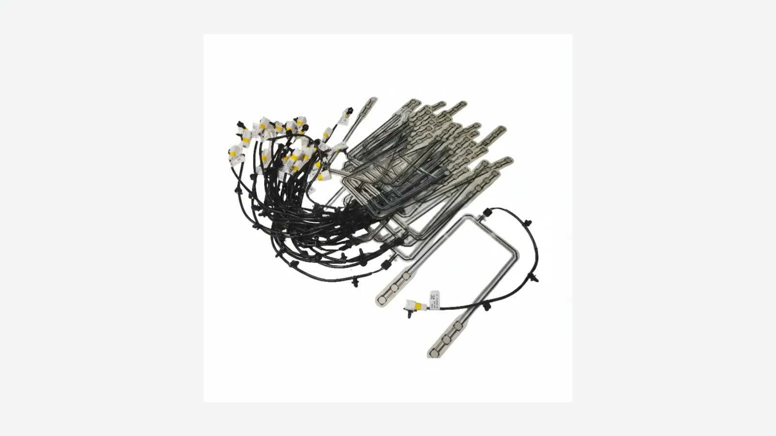
5. Validate the Finished Seat Sensor Harness Route
Validation should reproduce the production route and restraints. A flat coupon remains useful for comparing tail constructions; a connector bench test remains useful for terminal and housing behavior. Neither reproduces the cushion suspension, frame, clips, seat mechanisms, service access, or combined side load.
| Test block | Representative specimen | Conditions to define | Monitor and inspect | Acceptance owner |
|---|---|---|---|---|
| Drawing/dimensional review | As-built mat, transition, connector, harness, and seat | Tail stack, radii, no-bend zones, clip and mating locations, worst tolerance | Dimensions, route template, terminal/lock seating | Joint design team |
| Production assembly trial | Finished cushion and seat built in sequence | Operators, tools, trim attachments, allowed rework, lock verification | Live continuity where useful; crease, pinch, scrape, twist and partial-mate checks | Manufacturing engineering |
| Combined seat motion | Production-routed seat | Fore/aft, height, recline, loaded/unloaded cushion, service position | Tension, slack-loop containment, rub points, connector side load, signal continuity | Seat-system owner |
| Mechanical environment | Installed assembly with production restraints | Applicable ISO 16750-3:2023 or customer profile, axes, levels, duration, powered state | In-motion continuity; clips, abrasion, terminal/lock and tail inspection | OEM/program reliability |
| Climatic sequence | Installed assembly | Applicable ISO 16750-4:2023, rate, dwell, recovery, energized state | Electrical drift, insulation, adhesives, seals, terminal condition | Program specification |
| Connector/termination evidence | Exact production connection system | Applicable SAE/USCAR-2/customer requirements and routed side loads | Contact resistance, retention/locking, sealing where claimed, teardown | Connection-system owner |
| Post-test teardown | Tested seats | Inspection locations and magnification | Tail root, bend, transition, clips, abrasion points, terminals, seals | Agreed cross-functional team |
Pass criteria cannot be universalized from the cited standards. The program must define electrical discontinuity thresholds, allowed drift, visual defects, connector state, sample rationale, sequence, and report disposition. Keep the exact route photographs and as-tested part revisions with the report.
6. When an Integrated Pressure-Mat Tail Is Not the Best Choice
An integrated printed tail and short pigtail work best when the seat provides a controlled static bend, protected transition, accessible keyed connection, and a harness path with predictable motion. Change the architecture when those conditions cannot be created.
| Scenario | Why the integrated route is a poor default | Better direction to evaluate |
|---|---|---|
| Normal operation repeatedly bends the tail | Static PET or ordinary FPC guidance cannot establish dynamic life | Dynamically engineered copper FPC or a qualified moving cable separated from the sensor body |
| Connector must be blind-mated after trim | Tail and contacts may carry insertion error or side load | Relocate the interface, add a guided bracket, or use an intermediate serviceable harness |
| Seat travel leaves no protected loop volume | Slack alternates between tension and snag risk | Move the module/mating point, revise clips, or change the seat-harness branch architecture |
| Tail must twist tightly around a frame member | Combined torsion and bend invalidate a planar radius screen | Add route length and 3D support, move the exit, or transition earlier to a suitable wire harness |
| Frequent service pulls on the sensor-side connector | Miniature contacts and printed termination become structural load paths | Put the service disconnect at a supported harness interface |
| Environment requires a sealed connection at a moving joint | A sealed housing alone does not validate routed side load or the complete enclosure | Select a connection system and validation plan around the installed joint, seals, wire, taping, and motion |
A car seat pressure sensor may use a different interconnect architecture, but changing the sensor name does not remove the need to assign route, harness, controller, and validation ownership.
7. Eight Release Blockers That Stop Drawing Release
- No exact mating connector part numbers — family names, photos, colors, and cavity counts do not control a connection system.
- A bend begins at the mat root, termination, or stiffener edge — the stiffness transition is being used as an uncontrolled hinge.
- Seat travel was checked only at nominal position — combined fore/aft, height, recline, cushion load, and tolerance remain unknown.
- The pigtail is taut or trapped in any seat state — GM 17-NA-010 shows why connection strain must be corrected at the route.
- A trim attachment crosses the tail corridor — the 16-NA-145 failure path makes pinch/crease prevention a release item.
- Tape is the only abrasion and strain strategy — protection does not remove tension, twist, bad geometry, or clip movement.
- The connector lock cannot be seen, felt, gauged, or otherwise verified — partial mating can escape the assembly station.
- The only evidence is flat-coupon continuity — the finished seat route, connector, harness, motion, environment, and service state remain untested.
8. Frequently Asked Questions
What belongs in a seat sensor connector design specification?
Specify both mating connector part numbers, key/polarization, positions, terminals, locks, seals where used, pinout, accepted conductor or FPC, tail-to-wire transition, routed centerline, anchors, motion/service loop, assembly sequence, validation configuration, and change owner. Include the seat frame and movement envelope, not only an electrical schematic.
How should pressure mat tail routing pass through a moving seat?
Keep the controlled bend in a free span away from the mat root, termination, stiffener, and connector entry. Route the pigtail so cushion and suspension motion do not pull the connection. Anchor the harness after the connector, then contain enough slack for combined seat travel without allowing a loop to reach tracks, springs, motors, or sharp frame edges.
How much slack should a seat sensor harness have?
There is no universal length. Derive slack from the routed centerline at combined fore/aft, height, recline, cushion-load, tolerance, and service positions. The minimum state must not pull the tail, terminals, connector, or clips; the maximum state must keep the loop inside a protected envelope. Verify both in CAD and a production-representative seat.
Can connector color prevent a wrong under-seat connection?
Color can support assembly, but it should not be the only error-proofing control unless the customer interface specification explicitly allows that method. Mechanical keying, polarization, branch length, connector-position assurance where applicable, clear work instructions, and a verifiable lock state provide stronger controls. Review every adjacent connector that an operator or technician could reach.
Where should strain relief sit relative to the connector?
Place restraint so harness weight, seat motion, and service pull do not reach the contacts, while preserving the straight or otherwise supplier-approved connector entry. The exact distance and fixation depend on the connector application specification, wire or FPC construction, mating process, and motion. Do not create a hard hinge at the termination or stiffener edge.
Can IPC-2223 define a pressure-mat tail bend radius?
IPC-2223 provides flex and rigid-flex printed-board design context when the construction and contract invoke it. It does not automatically govern every screen-printed PET/silver pressure mat. Use the actual tail stack and supplier rule. This initial’s initial 2.5 mm PET/silver and R ≥ 12t copper/polyimide values must be replaced with verified JASPER data before release.
Does SAE/USCAR-2 qualify the complete seat occupancy sensor wiring system?
No. SAE/USCAR-2 addresses automotive electrical connector systems within its scope. The tail/termination, cable or harness, routed seat, pressure sensor, controller interface, and vehicle function each retain separate requirements. The applicable revision, connection class, routed side loads, specimen, and customer acceptance plan must be defined for the program.
What should be shared with a seat sensor supplier before tooling?
Share the seat-frame and cushion CAD, suspension and trim attachments, sensor location, tail-exit options, full movement envelope, selected connector drawings and mating half, pinout, harness route and clips, module/floor interfaces, assembly and service sequence, applicable environment, diagnostic boundary, validation matrix, and drawing/change-control owners.
9. Share the Seat Frame and Harness Route
Freeze the sensing body and interconnect together. A useful supplier package contains the seat section, pressure-mat location, tail root, full 3D route, cushion and mechanism movement, trim attachment points, exact connection system, harness anchors, assembly sequence, service disconnect, electrical interface, and acceptance plan. The seat occupancy sensor mat manufacturing case can show the type of flexible geometry JASPER handles, but it does not replace project-specific route evidence.
JASPER may be considered as one component-source option for a construction and DFM review. The seat, harness, controller, restraint, and vehicle owners must still approve their interfaces. Share the seat frame and harness route before tooling rather than sending only a connector photo or mat outline.
Technical References
- Source: IPC-2223E Flexible Printed Board Design. Accessed 2026.
- Source: SAE/USCAR-2-8 Connector Performance Specification. Accessed 2026.
- Source: GM Bulletin 16-NA-145 Passenger Presence Sensor Circuit. Accessed 2026.
- Source: Hyundai TSB 17-BE-002 Occupant Classification Mat Installation. Accessed 2026.
- Source: ISO 16750-3 Mechanical Loads for Vehicle Electrical Equipment. Accessed 2026.
- Source: Service Bulletin 17-NA-010. Accessed 2026.
- Source: Bulletin 16-NA-145. Accessed 2026.
- Source: IPC-2223 flex-board practice. Accessed 2026.
- Source: All Flex Solutions. Accessed 2026.
- Source: Minco. Accessed 2026.
- Source: Hirose FH12. Accessed 2026.
- Source: Hirose FH55/FH55M. Accessed 2026.
- Source: Molex Easy-On FPC/FFC application specification. Accessed 2026.
- Source: SAE/USCAR-2. Accessed 2026.
- Source: public USCAR change letter dated April 24, 2025. Accessed 2026.
- Source: ISO 16750-3:2023. Accessed 2026.
- Source: ISO 16750-4:2023. Accessed 2026.
- Source: ISO 19642-2:2023. Accessed 2026.
- Source: ISO 20653:2023. Accessed 2026.
Review the complete seat sensing stack before release
Send the cushion section, sensor zone, seat frame, harness route, output logic, environment, and validation boundary for review.