
Sensing principle
ControlRelease contact, resistance-responsive, FSR-type, or another confirmed route and its customer circuit.
Failure modeThe word membrane is mistaken for a complete electrical specification.
A flexible membrane seat pressure sensor uses released printed layers, sensing geometry, spacer or adhesive features, insulation, tail, and connector to create a thin component for a defined cushion location. The exact sensing principle remains project-specific.
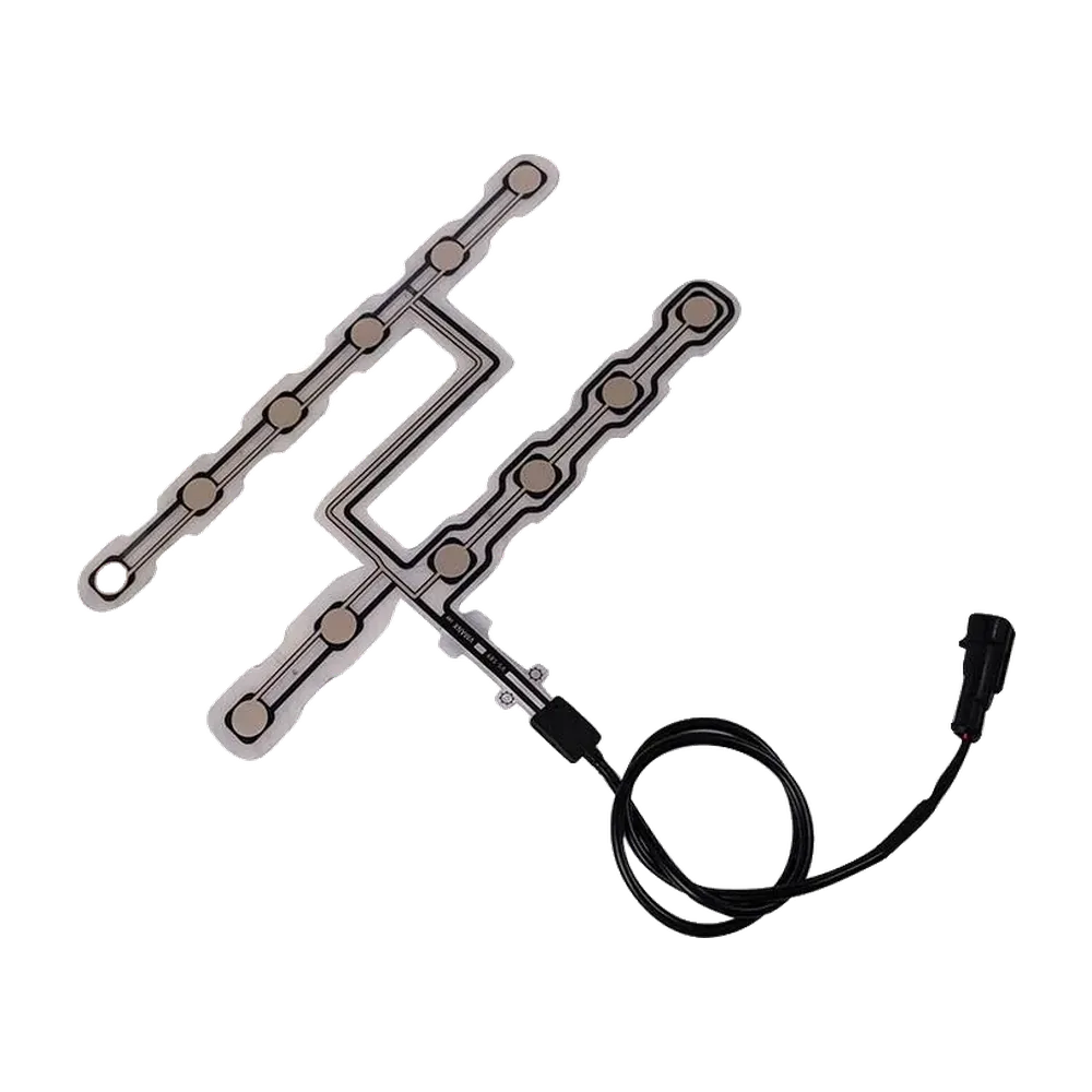
A flexible membrane seat sensor is a thin laminated component whose printed and die-cut layers can follow a custom outline and route signals out of the cushion.
The same manufacturing family can support contact-type, resistance-responsive, or confirmed FSR-type structures. The drawing must identify the actual sensing principle rather than treating membrane as one electrical behavior.
JASPER can own the released printed component and its production controls. Seat electronics, calibration, classification, warning logic, vehicle validation, and compliance stay with the system owner.
Layer names alone do not define electrical response or installed durability.
Release contact, resistance-responsive, FSR-type, or another confirmed route and its customer circuit.
Failure modeThe word membrane is mistaken for a complete electrical specification.
Control conductor width, spacing, active pattern, crossover, tail routing, registration, and test points.
Failure modeThe active zone or tail loses margin after print and die-cut tolerances.
Release openings, land width, vent path, bonding zones, edge distance, thickness direction, and substitutions.
Failure modePreload, trapped air, squeeze-out, or local stress changes response.
Select and control the project film or flexible support against bend, heat, moisture, assembly, and validation needs.
Failure modeAn unreviewed material change shifts stiffness, adhesion, or processing.
Define tail length, bend area, reinforcement, lead attachment, connector, strain relief, and seat exit.
Failure modeThe printed conductor cracks or peels where the flexible body leaves the cushion.
Inspect registration, bond, edge, continuity or response, appearance, connector, and conditioned samples.
Failure modeA visually clean laminate hides misregistration or an unstable active zone.
A useful cross-section connects material and geometry to the intended sensing behavior and installed seat.
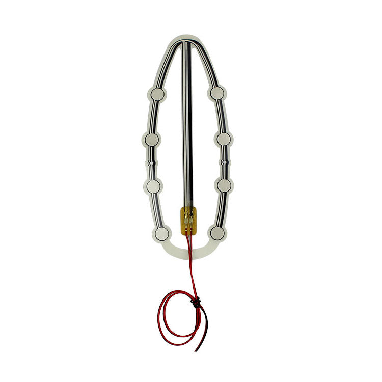
Openings, adhesive lands, vent paths, local support, and edge distances influence how the layers separate, contact, or transfer force. Release the cross-section together with the active pattern.
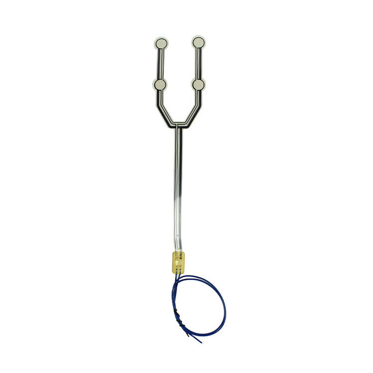
The sensor body may remain flat while its tail crosses foam grooves, frame edges, trim pulls, heaters, ventilation hardware, and moving seat structures. The route needs its own drawing and protection plan.
Review cushion section, foam behavior, upholstery tension, support, sensing zone, and installation boundary.
Release sensing principle, signal expectation, tail direction, cable protection, connector, and test access.
Check fit, false activation, occupied response, cable strain, connector fit, and repeatability in the real seat.
Lock drawing, material stack, circuit, connector, inspection, packaging, retained sample, and revalidation triggers.
Check printed continuity, active-pattern registration, spacer opening, customer circuit, connector, load path, and installed position.
Review trim pressure, adhesive squeeze, trapped air, spacer compression, support points, and lamination condition.
Inspect reinforcement, bend location, conductor route, adhesive edge, lead transition, assembly pull, and frame contact.
Compare material revision, print deposit, registration, adhesive, lamination pressure, conditioning, fixture, and seat stack.
The format is useful when geometry and printed interconnect matter as much as the sensing element.
Thin custom outlines with printed zones, tail routing, and customer connector interfaces.
Custom zone and tail layouts around folding, split, or modular cushion structures.
Repeated printed sensor modules with controlled installation and cable protection.
Non-standard cushions requiring a flexible outline and project-specific interconnect.
Custom modules where thin construction, service routing, and component evidence are important.
A sketch of the stack, active pattern, and cable route is enough to expose most early manufacturing risks.
It is a thin laminated sensor component using printed and die-cut flexible layers to create a project-defined contact, resistance-responsive, FSR-type, or other confirmed sensing structure.
No. Membrane describes the flexible layered format. The actual sensing principle must be confirmed from the electrical requirement and released construction.
Yes. JASPER can review the outline, zones, conductor pattern, spacer openings, adhesive lands, tail, reinforcement, connector, labeling, and component tests.
Foam, trim, support, heaters, ventilation, installation pressure, and cable routing can change preload, force transfer, flexibility, and service life.
Approve layer registration, dimensions, electrical response, bond, tail transition, connector, fit, false activation, occupied response, and the installed seat condition.
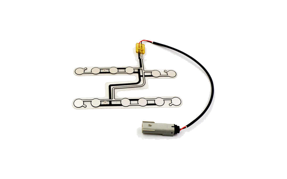
Compare all custom seat pressure and occupancy sensor routes.
Review Resource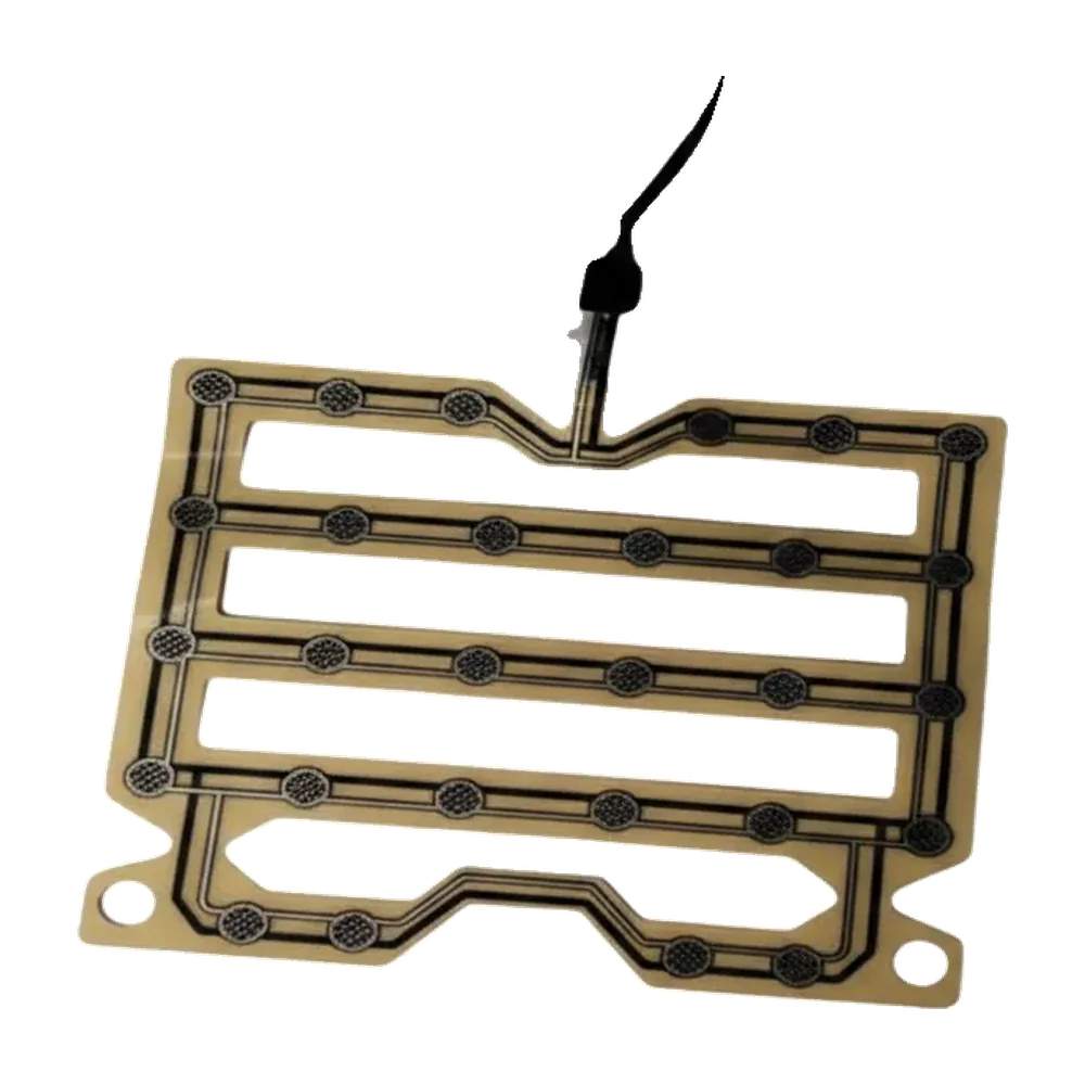
Connect the printed structure to the pressure response and seat-level test.
Review Resource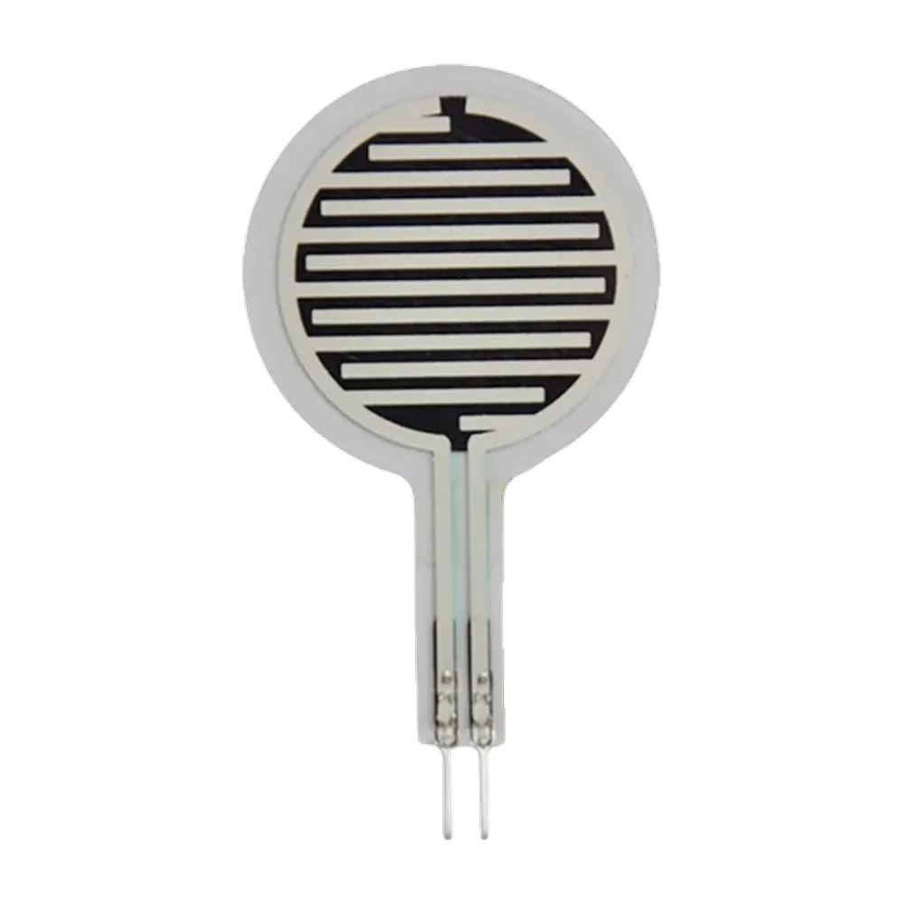
Review when force-sensitive resistor behavior is an explicit requirement.
Review ResourceJASPER can review the flexible layers, sensing geometry, spacer, adhesive, interconnect, component evidence, and production controls for your custom seat sensor.
Share the project basics. JASPER will review the stack, materials, connector, quantity, and production risks.