
Seat pressure sensor placement should be selected from the loaded, fully trimmed seat—not from a foam top view or a bare-sensor bench test. For OEM seat engineers and sourcing teams, the best location is the zone where target occupants create a repeatable compression path through cover, foam, sensor, and support while empty-seat preload, edge loading, posture changes, and trim tension stay outside the activation window. This guide compares five installation planes and shows how to validate them. It does not set a universal trigger force, identify a rail-mounted seat-position sensor, or establish occupant-classification or vehicle compliance.
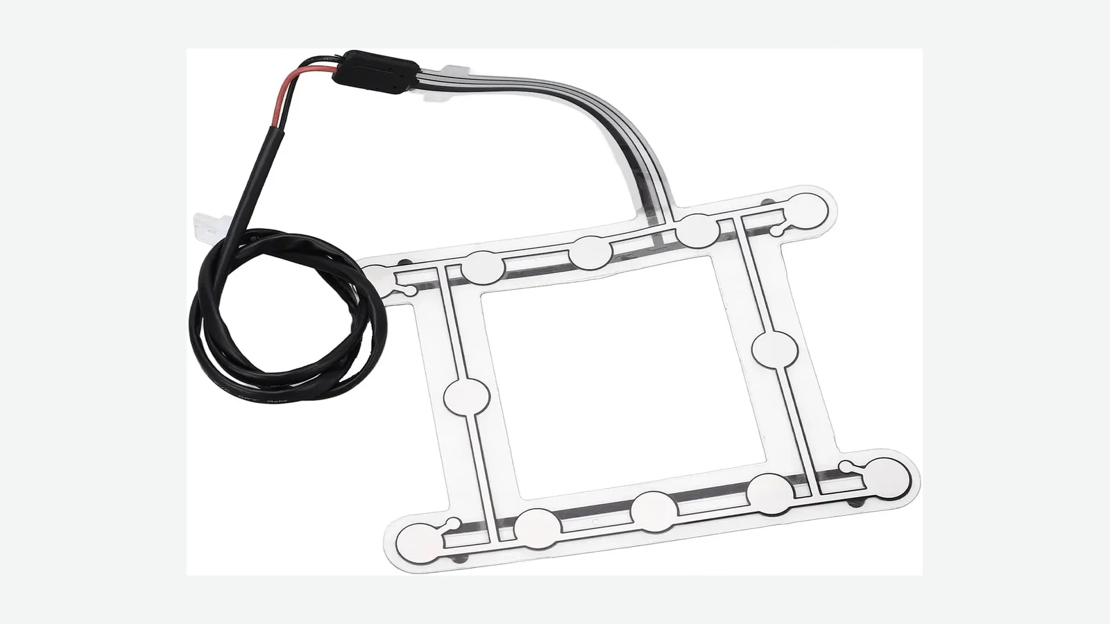
Here, “pressure sensor” means a thin occupancy, contact, or force-responsive mat integrated into the cushion stack. It does not mean the fore-aft position sensor mounted on a seat track. A seat occupancy sensor mat is only one input: the trimmed seat, support structure, electronics, software, thresholds, diagnostics, and validation plan determine the finished result.
Seat pressure sensor placement is a seat-system decision. The mat, trim, foam, support structure, electronics, thresholds, diagnostics, and validation plan must be reviewed as one production-intent stack.
1. Why Seat Pressure Sensor Placement Fails in a Real Cushion
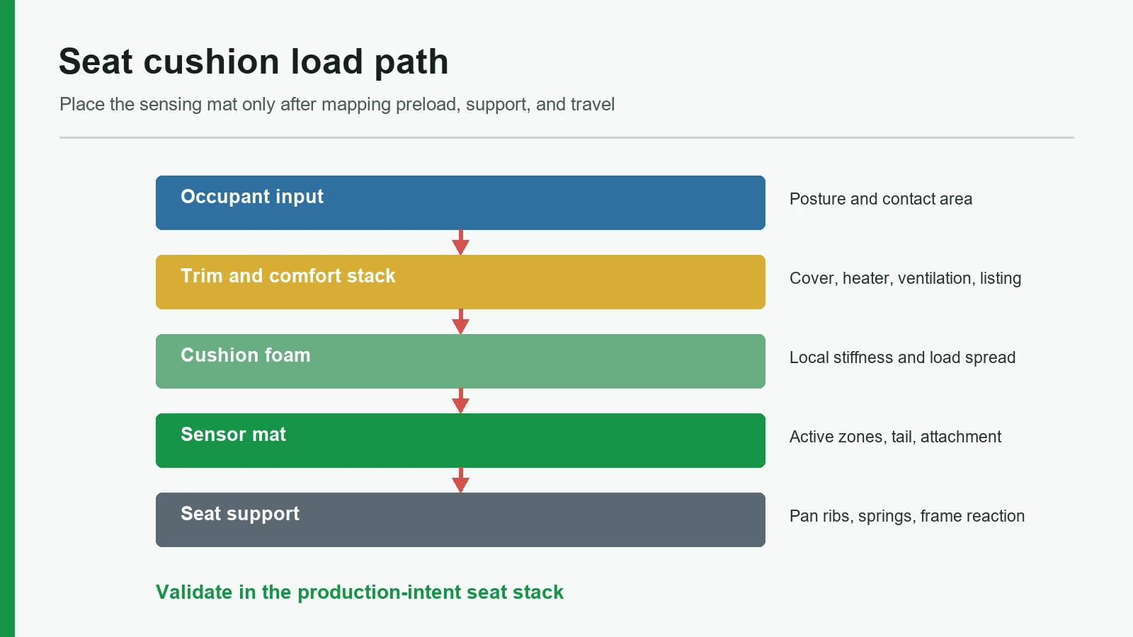
Seat pressure sensor placement fails when the chosen zone receives a different share of load after the cover, foam, heater, trim attachments, pan, and suspension are assembled. A useful definition follows: the seat foam load path is the route by which occupant force travels through the cushion stack and returns through the seat support. The sensor reads one local part of that path. It does not automatically read total occupant weight.
That distinction is visible in public automotive evidence. In a 2016 response filed with NHTSA, IEE stated that seat geometry and vehicle environment change where occupant or child-seat pressure reaches the cushion; sensor placement, calibration, mats, and algorithms therefore vary by vehicle application (IEE response to NHTSA DP16-001). In Suzuki Recall 19V-343, the company identified OCS sensors that were not optimally positioned relative to cushion shape as the cause of potential adult misclassification. The remedy replaced the cushion-and-mat assembly with revised pad placement (NHTSA Recall 19V-343).
The failure chain starts before the switch threshold
| Seat input | Mechanical change | What reaches the sensing zone | Likely symptom to investigate |
|---|---|---|---|
| Occupant slides forward or leans laterally | Pelvis contact patch moves toward an edge or bolster | Target zone loses load while another region gains it | Late activation, state chatter, or missed target posture |
| Cover tension or a trim attachment crosses the mat | Local preload rises before anyone sits down | Empty-state pressure moves toward activation | False occupied state or incomplete release |
| Foam hardness, thickness, zoning, or set changes | Load spreads, concentrates, or bottoms against support differently | Same external load produces a different local response | Cushion-to-cushion threshold shift |
| Bolster, pan rib, edge support, or suspension spring carries more reaction | Load bypasses or reinforces the selected plane | Sensor sees only a changed fraction of the total | Seat-build or position sensitivity |
| Mat or tail shifts, folds, or is pinched during trim assembly | Printed layers bend at a sharp, repeated strain point | Electrical resistance rises or a circuit opens | Intermittent fault or permanent open circuit |
Tekscan's automotive application page lists stitching, bolsters, wire stays, foam stiffness, seat angle, lumbar support, and cover material as variables that change pressure maps. Its braking example also shows the high-pressure region moving as the driver's posture and support change (Tekscan Automotive Seat Testing & Design). GM Bulletin 16-NA-145 supplies a separate assembly lesson: a sensor tail pinched during trim hog-ringing could crease, then flex during ingress, egress, and knee loading until the printed circuit became open or high-resistance (GM Bulletin 16-NA-145).
Threshold tuning cannot make an unstable mechanical path stable. First separate load-path errors, assembly damage, electrical behavior, and classification logic. Then tune only the layer that owns the observed variation.
2. A 10-Point Framework for Seat Pressure Sensor Placement
A defensible placement review covers ten items in order: system function, target load map, foam, trim stack, supports, installation plane, assembly control, signal window, variation, and system compliance. Skipping the early mechanical items usually pushes the team toward threshold changes that hide one condition while weakening another.
2.1 Define the decision and output before drawing a mat
Start with the state the seat system must deliver. A simple seat-belt-reminder input may need stable empty and occupied states plus fault detection. A comfort feature may need relative load or zone information. Occupant classification can require a pattern, calibrated electronics, software, and diagnostics that a single contact cell cannot provide.
The 2016 IEE filing makes this scope distinction concrete: its sensor-mat subcomponent excluded the electronics, algorithm, and calibration included in its complete OCS component (IEE response to NHTSA DP16-001). The RFQ should therefore name the physical input, electrical output, decision owner, diagnostic state, and final acceptance authority.
The specification defines empty, occupied, transitional, and fault behavior, then assigns each decision to the mat, controller, seat system, or vehicle.
The drawing says only “occupancy sensor” and assumes one switching force will also solve posture, object discrimination, diagnostics, and vehicle logic.
2.2 Map target and non-target regions on the complete seat
A pressure map is useful only when its coordinates can return to the cushion drawing. Fix the map to seat datums, mark the intended active zone, and overlay trim trenches, bolsters, foam transitions, heater boundaries, ventilation passages, pan features, and tail exits. Capture the fully trimmed production-intent build, not only a skived foam block.
Posture belongs in this map. SAE paper 2005-01-0461 describes OCS development using test persons, child seats, special buttock dummies, seating positions, foam stiffness, cover preload, and environmental temperature. Its simulation model was validated against material, component, and physical tests (SAE 2005-01-0461). A separate SAE study measured people of different morphologies in different postures and recorded different pressure distributions (SAE 2005-01-2703).
The map should include the target occupant states and the non-target loads that the program must reject or handle. Centered upright posture alone is not enough. Fore-aft movement, lateral lean, ingress, egress, knee loading, objects, and applicable child-restraint conditions can move or bridge the load path.
Every proposed sensing cell is traceable to a loaded-seat map and a named state in the validation plan.
The active area is centered by appearance, copied from another cushion, or sized only to cover the geometric middle.
2.3 Characterize foam by method, location, and condition
Foam density does not substitute for firmness or load-deflection behavior. The Polyurethane Foam Association treats density and firmness as separate properties (PFA Foam Performance). ISO 2439:2008 provides several indentation-hardness methods; results obtained under its conditions generally cannot be used directly for design. ISO 3386-1:2025 covers compression stress-strain characterization of low-density flexible cellular material up to 250 kg/m³. ASTM D3574-25 also establishes that laboratory results may differ from service behavior (ISO 2439:2008, ISO 3386-1:2025, ASTM D3574-25).
Record the method, specimen geometry, sampling position, compression level, conditioning, test environment, and foam lot beside each value. Map local zones rather than assigning one hardness number to the cushion. BASF Elastoflex W formulations span 30 to 80 kg/m3, and one seat system can use different hardness zones (BASF Elastoflex W).
Foam comparison point: Use 70 kg/m3 only to organize the first molded-cushion comparison under ASTM D3574. Published automotive seating systems span 62-74 kg/m3 in one disclosed range, while other formulations cover a broader 30-80 kg/m3 range. Release the seat design from method-tagged foam data, local cushion geometry, and the measured sensor response in the complete load path.
A 2019 SAE paper offers a scoped example, not a rule: in its tested setup, maximum and mean interface pressure rose by 0.09 kPa and 0.04 kPa for each 1 kPa increase in cushion hardness (SAE 2019-01-5024). The result proves sensitivity to the tested foam system; it does not supply a sensor threshold for another seat.
The supplier receives a cushion section plus method-tagged foam data for the sensing zone and adjacent supports.
A density value, trade name, or nominal hardness is treated as a complete prediction of local sensor pressure.
2.4 Treat trim, heater, and ventilation layers as load-path parts
Cover tension can preload a shallow sensor before an occupant arrives. Seams and listing wires can create lines of concentrated reaction. A heater, spacer textile, ventilation duct, or perforated laminate can change local compliance and bridge a sensing cell. These features are not packaging notes; they are mechanical boundary conditions.
SAE 2005-01-0461 explicitly included covering materials and preload among the OCS layout variables. Tekscan identifies stitching, wire stays, bolsters, and cover materials as pressure-map factors.
Shallow A-surface stack
occupant load
cover + laminate + seams / listing attachments
↘ local trim preload
pressure or contact mat near the foam surface
molded foam: local hardness, thickness, trenches, bolsters
seat pan or suspension reaction
Prototype seats use production-intent cover material, stitch pattern, heater or ventilation layer, attachments, and assembly tension.
An untrimmed-foam pass is accepted as the final placement result.
2.5 Account for edge support, pan ribs, suspension, and preload
The seat's support system decides where force returns. A hard edge, bolster foundation, pan rib, spring, suspension mat, or mounting fixture may carry load around the proposed cell. Empty-seat contact between layers can also apply preload that moves activation and release closer together.
Ford and Lear researchers list seat structure, suspension, materials, geometry, and test setup as variables in complete-seat load-deflection results (SAE 2017-01-1391). An IEE patent provides a clear mechanical example: a suspension-mounted module between cushion and springs sees part of the occupant force and part of the spring reaction (US9463714B2). That is a disclosed embodiment, not a universal seat architecture, but it shows why support reaction belongs on the placement drawing.
Under-foam B-surface stack
occupant load
cover, heater / ventilation stack, molded foam
↘ load spreads laterally through the foam
pressure mat or module below the main foam
spacer, pan, support plate, or suspension reaction
The test seat uses the intended pan, suspension, edge supports, adjustment state, and mounting fixture; empty-state preload is measured before occupant trials.
The cushion is tested on a rigid bench plate even though the production seat relies on a compliant suspension or vehicle structure.
2.6 Compare five installation planes before selecting one
No installation plane wins every program. The correct choice follows the required signal, cushion architecture, protected space, service path, and acceptable sensitivity to trim or support variation.
| Placement plane | What it mainly reads | Main advantage | Main risk | Not the best choice when… |
|---|---|---|---|---|
| Below cover, above foam (A-surface) | Short-path surface pressure and local cover preload | Strong local response; direct zone layout | Trim seams, attachment wires, feel, heater stack, and wrinkles can dominate | Cover variants or high trim preload make empty and occupied distributions overlap |
| Shallow foam pocket or embedded layer | Local foam compression near the occupant | Can protect the mat and control depth | Pocket geometry, molding tolerance, and serviceability become critical | The foam process cannot hold position or protect the tail without folds |
| Below main foam, above pan or suspension (B-surface) | Load dispersed through foam plus support reaction | Protected from surface objects and trim read-through | Foam geometry, humidity, pan ribs, and support contact can blur or redirect load | The target requires fine surface-zone discrimination after thick or highly zoned foam |
| Suspension-mounted module | Cushion force against a spring or suspension member | Can reduce sensitivity to visible trim variants | Spring geometry, preload, seat-frame packaging, and moving interfaces control the result | Suspension variants or seat adjustments change the reaction path more than the target state does |
| Structural load sensor at frame or rail | Reaction through seat structure | Better fit for total structural-load objectives | Different sensor class, packaging, cost, multi-point calibration, and frame cross-loads | The project needs a thin mat, local pressure map, or simple trim-line integration |
The B-surface idea is easy to misunderstand. One Delphi patent places a pressure-responsive device under the foam and explains that load disperses as it travels through the cushion; its notched-foam embodiment intentionally changes that spread (US20080116725A1). A sensor under the seat cushion is therefore not isolated from foam design. It is more dependent on the entire foam-to-support path.
The concept review compares at least two mechanically distinct planes against the same state model and seat build.
“Under foam” is selected as a generic location without naming the pan, suspension, spacer, support contact, and foam path below the active zone.
2.7 Control occupancy sensor mat installation and the tail path
Position tolerance must be visible and inspectable. Use molded locators, drawing datums, approved templates, image records, or other controls suited to the seat process. Define allowable translation, rotation, wrinkle, and adhesive condition from the validated design rather than from an installer’s judgment. Keep the active cells and tail clear of trim attachments, sharp foam cutouts, hinges, slide mechanisms, and moving brackets.
Hyundai TSB 17-BE-002 illustrates the discipline on one Accent platform: the replacement mat is aligned to a foam indentation, checked for access to cover-attachment points, and adhered only after its position is confirmed (Hyundai TSB 17-BE-002). GM Bulletin 16-NA-145 shows the complementary failure: trim hog-ringing trapped the tail against a tiedown feature, creating a crease that could flex into an open or high-resistance circuit.
The approved sample records the mat outline, cell coordinates, locator condition, adhesive pattern, tail exit, strain relief, connector, and trim-clearance check.
The installation instruction says “center on foam” but provides no datums, tolerance, locator, tail route, or post-trim inspection.
2.8 Define activation and release as distributions, not one number
A threshold is useful only when the mechanical distributions do not overlap. Plot the highest valid empty-seat response, the lowest valid target-occupied response, activation, release, and any debounce or dwell rule under each required condition. For a contact mat, include switch closure, opening, and hysteresis. For an analog or multi-zone sensor, include the conditioned signal and decision logic that the project actually owns.
Do not convert occupant mass directly into local sensor force. Contact area, posture, foam, trim, and support sharing can change local pressure while total load remains similar. If valid empty and occupied data overlap after mechanical variation is included, moving the electronic threshold only trades one error for another.
| State | Mechanical evidence | Electrical evidence | Required decision treatment |
|---|---|---|---|
| Empty | Production-intent trim and support at the highest valid preload | Valid response remains inside the empty envelope | Report empty without approaching activation margin |
| Occupied | Lowest valid target load path across required positions | Valid response reaches the occupied envelope | Report occupied after the approved qualification rule |
| Transitional | Occupant moves, enters, exits, or crosses a boundary | Response changes or sits between envelopes | Apply the owned dwell, debounce, or previous-state rule |
| Fault | Open, short, implausible zone pattern, or lost connection | Diagnostic condition lies outside valid state evidence | Report the approved fault state; do not relabel it empty |
The drawing and validation report show separate empty and occupied envelopes, release behavior, transitional treatment, and fault detection.
The specification publishes a universal “trigger weight” without the cushion stack, loading interface, test condition, or output definition.
2.9 Test build, environment, and aging variation in the seat
The material coupon and bare mat are screening tools. Final evidence must include assembled seat conditions capable of changing load transfer. SAE 2005-01-0461 names foam stiffness, cover preload, seating position, dummy or child-seat type, and environmental temperature in a sensor-mat development program. Delphi patent US6818842B2 identifies cushion humidity as a variable in one under-foam pressure architecture (US6818842B2).
Use named methods for material baselines. ISO 1856:2018 covers compression set for flexible foam, while ASTM D3574-25 provides multiple polyurethane-foam test methods (ISO 1856:2018). Then correlate preconditioned material and component results to the production-intent seat. Do not assume heat, humidity, or cycling always moves the signal in one direction; measure before and after the program-defined exposure.
The validation matrix includes foam lots, trim builds, support assemblies, installation tolerance, environmental states, aging states, and service disturbances tied to owned acceptance limits.
One room-temperature prototype is tuned until it passes, then becomes the specification.
2.10 Keep component validation separate from vehicle compliance
A sensor mat can pass continuity, switching, dimensional, environmental, and seat-integration checks without certifying a vehicle. NHTSA answered this question directly in Interpretation 22492: FMVSS 208 generally applies to new vehicles rather than an individual sensor mat, and the vehicle manufacturer is responsible for self-certification (NHTSA Interpretation 22492). Current 49 CFR 571.208 includes finished-vehicle automatic-suppression tests with specified child-restraint and small-adult conditions (49 CFR 571.208).
A shallow pressure or contact mat is not the best choice when the required decision depends on occupant-versus-object classification across conditions that produce overlapping pressure patterns, when the cover stack cannot hold a stable preload, or when the seat architecture offers no protected tail route. Alternatives may include multi-zone pressure sensing, a suspension or structural-load architecture, capacitive sensing, or another system-level method. IEE's BodySense page, for example, describes capacitive occupant classification rather than a pressure-profile mat (IEE BodySense). The requirement should select the technology—not the availability of a familiar mat.
The compliance matrix names the component supplier, Tier 1, OEM, controller owner, seat-validation owner, and vehicle-certification owner separately.
A supplier proposal describes a loose sensor mat as “NHTSA approved” or “FMVSS 208 certified.”
3. A Six-Step Placement and Approval Process
The placement process should move from owned system states to physical evidence, then finish with a controlled seat build. It should not begin with a catalog outline.
Step 1 — Freeze the state model and owners
List the required states, output type, transition treatment, diagnostics, and acceptance authority. For a passenger seat occupancy sensor, name the exact front or rear cushion; do not release one zone map for unlike seats.
Step 2 — Mark the section, active zone, and forbidden zones
Issue a top view and section through the intended zone. Mark foam transitions, trim trenches, heater or ventilation layers, pan and suspension contacts, tail exit, connector, attachments, moving hardware, and service access.
Step 3 — Map the production-intent seat
Measure empty preload and loaded pressure on the fully trimmed seat across required occupants, postures, positions, and non-target loads. Tie the map to hard datums so a cell can be moved deliberately rather than by visual centering.
Step 4 — Prototype distinct mechanical candidates
Compare more than one credible plane when risk justifies it—for example, a shallow A-surface zone against a B-surface or suspension concept. Keep the electronics and state definitions controlled while the mechanical path changes.
Step 5 — Run the cross-factor matrix
Use the project's applicable limits, not generic values copied from another seat. JASPER's public testing and validation planning page uses the same useful boundary: name the characteristic, condition, method, sample stage, and acceptance owner.
| Factor | Minimum comparison | Evidence to retain |
|---|---|---|
| Occupant or loading state | Required target, empty, transitional, and non-target states | Raw map or signal plus final state |
| Posture and seat adjustment | Program-defined centered and displaced positions | Datum-linked position record |
| Foam | Approved lots, local zones, and conditioned states | Method-tagged foam data and cushion ID |
| Trim stack | Cover builds, attachments, heater/ventilation variants | Build record and preload response |
| Support | Intended pan, suspension, edge support, and fixture | Support configuration and empty baseline |
| Installation | Position and rotation limits, wrinkle, tail, connector | Photo or scan against drawing datums |
| Environment and aging | Program-defined pre/post states | Exposure record, recovery time, before/after data |
Step 6 — Release the approved build and change triggers
Freeze the mat drawing, production-intent seat, acceptance evidence, and diagnostic rules together. A foam, trim, heater, support, mat, tail, connector, electronics, software, or process change should enter engineering change control before reuse of the original correlation.
Drawing and sample-approval checklist
| Required input or record | Approval question |
|---|---|
| Seat top view and cushion section | Are active and forbidden zones tied to stable datums? |
| Foam specification and local test data | Are method, location, lot, condition, and thickness recorded? |
| Complete trim stack | Are seams, trenches, attachments, heater, and ventilation features shown? |
| Pan, suspension, ribs, and edge supports | Is the reaction path under every cell visible? |
| Mat outline and cell coordinates | Are translation, rotation, wrinkle, and flatness limits inspectable? |
| Tail, strain relief, and connector | Are pinch, fold, motion, and service paths controlled? |
| State and electrical specification | Are activation, release, transition, fault, and timing owned? |
| Validation matrix and raw results | Do valid empty and occupied envelopes remain separated? |
| Approved physical sample | Does it match the released drawing and production assembly? |
JASPER's public real sample geometry but explicitly does not claim a threshold, classification accuracy, durability result, regulatory compliance, or vehicle-level performance. That is the correct evidence boundary for a sample image: it can prove what was built, not how the finished seat performs.
4. Eight Release Blockers That Disqualify a Placement Proposal
These faults override a clean bench result for a car seat pressure sensor:
- No cushion section or hard datums — the installed zone cannot be reproduced or audited.
- A universal trigger weight — local pressure is being confused with total occupant load.
- Approval on bare foam only — trim, heater, attachments, pan, and suspension are missing.
- A layout copied from another seat — application-specific load and support paths were not re-established.
- Cells or tails crossing trenches and attachments — preload, pinch, fold, and trace damage remain uncontrolled.
- No release or empty-state margin — an activation pass may hide a false-occupied or state-chatter problem.
- Electronics retuned before mechanical diagnosis — one posture is improved by sacrificing another condition.
- “NHTSA approved” or “FMVSS 208 certified” mat wording — the supplier is misrepresenting a vehicle-level compliance boundary.
5. Frequently Asked Questions
What is the best seat pressure sensor placement?
The best seat pressure sensor placement is the zone where required occupants create a repeatable loaded-seat response while empty preload, posture changes, and non-target loads remain outside the decision window. It must be chosen from the fully trimmed seat with its intended support structure; no location is universal.
Can a sensor under the seat cushion detect occupancy?
Yes, a sensor under the seat cushion can detect occupancy when foam compression and support reaction create a separable signal. It reads load after the foam has spread or redirected it, so foam geometry, humidity, pan ribs, suspension, and spacers belong in the correlation and validation plan.
How does foam stiffness affect the sensor trigger?
Foam stiffness can change indentation, contact area, and local pressure at the mat, but the direction and size depend on the cushion, position, trim, and support. Record a named ISO or ASTM method and test the finished seat. Do not turn one foam value into a universal trigger correction.
Should the sensor mat be centered on the cushion?
Not automatically. Center the coordinate system on stable seat datums, then place active cells where the validated target load map supports them. Suzuki Recall 19V-343 shows why geometric centering is not enough: cushion-relative sensor position affected occupant classification on that vehicle program.
Can trim tension cause an occupied signal on an empty seat?
Trim tension can preload a shallow mat or bridge a local cell, moving the empty response toward activation. Seams, listing wires, tiedowns, heater layers, and wrinkles can intensify the effect. Measure the empty baseline after the production-intent cover is assembled and after relevant trim variants are built.
What controls occupancy sensor mat installation?
Occupancy sensor mat installation needs drawing datums, position and rotation limits, locators or an approved template, adhesive condition, wrinkle criteria, trim-clearance checks, and a controlled tail route. Hyundai TSB 17-BE-002 provides a platform-specific example of aligning a mat to a foam indentation before adhesion.
When is a pressure or contact mat not the best choice?
A pressure or contact mat is not the best choice when valid occupant and non-target pressure patterns overlap, when trim preload cannot be controlled, or when no protected tail route exists. Multi-zone, capacitive, suspension-mounted, or structural-load sensing may fit those requirements better after a system-level review.
Can a seat sensor mat be FMVSS 208 certified?
No. NHTSA Interpretation 22492 applies FMVSS 208 generally to new vehicles, not an individual sensor mat; the vehicle manufacturer self-certifies compliance. A component supplier can provide test evidence for the OEM or Tier 1, but should not label the loose mat NHTSA-approved.
What should an OEM send for a placement review?
Send the cushion top view and section, intended sensing and forbidden zones, complete trim stack, foam specification and local test method, pan or suspension geometry, tail and connector route, electrical state definition, environmental conditions, seat variants, and the planned validation matrix.
6. What to Send Next
Freeze the state model, map the loaded seat, compare credible installation planes, and approve the mat only with the production-intent cushion stack. For a custom review, send the cushion section and intended sensing zone through JASPER's engineering review route, together with the trim stack, support geometry, tail direction, connector, and validation boundary. The same evidence package can be used with another qualified sensor manufacturer or seat-system integrator; it is meant to make the mechanical decision auditable before tooling or threshold tuning.
Technical References
- Source: NHTSA Recall 19V-343 Occupant Classification Sensor Placement. Accessed 2026.
- Source: NHTSA Interpretation 22492 FMVSS 208 Component Scope. Accessed 2026.
- Source: ISO 2439:2008 Flexible Cellular Material Indentation Hardness. Accessed 2026.
- Source: ASTM D3574-25 Flexible Cellular Material Test Methods. Accessed 2026.
- Source: SAE 2005-01-0461 Occupant Classification Sensor Mat Layout. Accessed 2026.
- Source: IEE response to NHTSA DP16-001. Accessed 2026.
- Source: NHTSA Recall 19V-343. Accessed 2026.
- Source: Tekscan Automotive Seat Testing & Design. Accessed 2026.
- Source: GM Bulletin 16-NA-145. Accessed 2026.
- Source: SAE 2005-01-0461. Accessed 2026.
- Source: SAE 2005-01-2703. Accessed 2026.
- Source: PFA Foam Performance. Accessed 2026.
- Source: ISO 2439:2008. Accessed 2026.
- Source: ISO 3386-1:2025. Accessed 2026.
- Source: ASTM D3574-25. Accessed 2026.
- Source: BASF Elastoflex W. Accessed 2026.
- Source: Huntsman RUBIFLEX Gradient Hardness. Accessed 2026.
- Source: SAE 2019-01-5024. Accessed 2026.
- Source: SAE 2017-01-1391. Accessed 2026.
- Source: US9463714B2. Accessed 2026.
- Source: US20080116725A1. Accessed 2026.
- Source: Hyundai TSB 17-BE-002. Accessed 2026.
- Source: US6818842B2. Accessed 2026.
- Source: ISO 1856:2018. Accessed 2026.
- Source: NHTSA Interpretation 22492. Accessed 2026.
- Source: 49 CFR 571.208. Accessed 2026.
- Source: IEE BodySense. Accessed 2026.
Review the complete seat sensing stack before release
Send the cushion section, sensor zone, seat frame, harness route, output logic, environment, and validation boundary for review.