
Seat identity
ControlRelease vehicle program reference, seat position, cushion revision, left or right orientation, and module variant.
Failure modeThe wrong mat revision is fitted to a different passenger cushion.
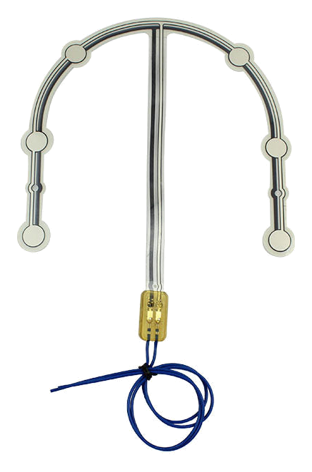
A passenger seat occupancy sensor is installed within a specific seating position and responds when the project-defined passenger load reaches its sensing area.
This page covers pressure and membrane seat sensors. Camera, radar, in-cabin monitoring, ECU classification, and restraint decisions are different system layers and remain outside the supplied component.
JASPER can customize the sensor outline, zones, printed structure, tail, lead, connector, component test, and packaging against the customer seat drawing and validation plan.
A sensor cannot classify a seat position that has not been mechanically defined.
Release vehicle program reference, seat position, cushion revision, left or right orientation, and module variant.
Failure modeThe wrong mat revision is fitted to a different passenger cushion.
Map common posture, off-center posture, bolsters, seams, support, and intended zone coverage.
Failure modeThe active area misses a credible seated condition.
Define objects, cargo, kneeling, edge loading, trim preload, seat fold, and service pressure.
Failure modeThe customer system receives an unintended occupied input.
Name the layer, orientation, datums, adhesive or restraint, tail exit, cable route, connector, and assembly sequence.
Failure modeThe sensor shifts, folds, or becomes preloaded during trimming.
Confirm contact, resistance-responsive, FSR-type, or other input and the customer measurement circuit.
Failure modePassenger intent is mixed with an unspecified electrical output.
Separate component evidence from customer classification, SBR, restraint, camera, radar, ECU, and vehicle validation.
Failure modeA seat mat is marketed as a complete detection system.
The same product name can describe very different front, rear, and specialty seat packages.
| Decision | Options to Review | Release Question |
|---|---|---|
| Seat position | Front passenger, rear left, rear center, rear right, folding seat, removable module, or specialty seat | Which exact cushion revision receives the sensor? |
| Coverage zone | Single broad zone, multiple zones, local zones, exclusions, edge restrictions, or custom pattern | Which passenger postures must load the component consistently? |
| Sensor route | Contact-type mat, pressure-responsive membrane, confirmed FSR-type sensor, or project structure | What electrical input does the customer controller expect? |
| Installation stack | Under foam, inside foam, below trim, above support, heater or ventilation relationship | Which adjacent layers create load, preload, movement, or abrasion? |
| Interconnect | Tail direction, lead length, connector, pinout, strain relief, seat harness, and service disconnect | How does the signal leave this specific seat position? |
| Validation | Component fixture, installed cushion, complete seat, system integration, or vehicle test | Who approves each level and what evidence authorizes production? |
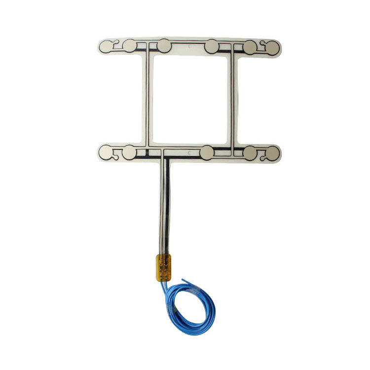
Cushion width, bolster shape, foam sections, trim seams, seat fold, occupant posture, and support geometry change where pressure reaches the sensor.
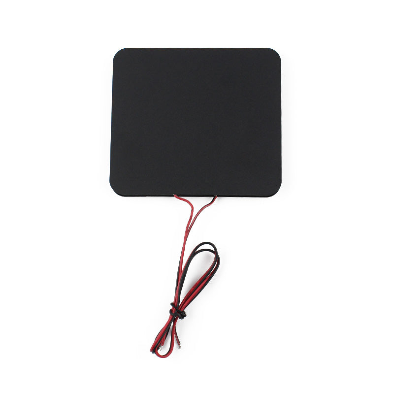
Occupant classification can include sensors, ECU logic, calibration, diagnostics, seat structure, restraint interfaces, and vehicle validation. JASPER scope is limited to the released seat sensor component.
Review cushion section, foam behavior, upholstery tension, support, sensing zone, and installation boundary.
Release sensing principle, signal expectation, tail direction, cable protection, connector, and test access.
Check fit, false activation, occupied response, cable strain, connector fit, and repeatability in the real seat.
Lock drawing, material stack, circuit, connector, inspection, packaging, retained sample, and revalidation triggers.
Check posture coverage, foam load transfer, zone placement, sensor output, connector, customer circuit, and threshold logic.
Review object cases, active-zone size, preload, cushion response, measurement method, and customer classification boundary.
Compare cushion geometry, foam, trim, installation, sensor revision, harness, electronics, and calibration.
Inspect tail restraint, cable route, connector, seat fold or slide, cushion shift, and customer filtering.
The page remains focused on pressure and membrane components, not camera or radar systems.
Custom sensing zones and routing for a named front-seat cushion.
Position-specific mats for split, folding, or modular rear cushions.
Compact or linked zones around center-seat geometry and harness constraints.
Pressure-based occupancy inputs for taxis, shuttles, and specialty cabins.
Non-standard passenger cushions requiring shaped sensors and project connectors.
A front passenger cushion, rear bench, and specialty module should not share assumptions.
No. This page covers pressure and membrane components inside the cushion. Camera, radar, in-cabin monitoring, and related processing are separate systems.
No. JASPER supplies the released component. Classification logic, calibration, diagnostics, restraint decisions, vehicle integration, and compliance remain with the system owner.
Yes. Different cushion shapes, load paths, trim, support, routing, connectors, and passenger postures often require different zones and outlines.
Send the exact seat position, cushion drawing, active zone, passenger and object cases, signal expectation, tail route, connector, samples, and validation plan.
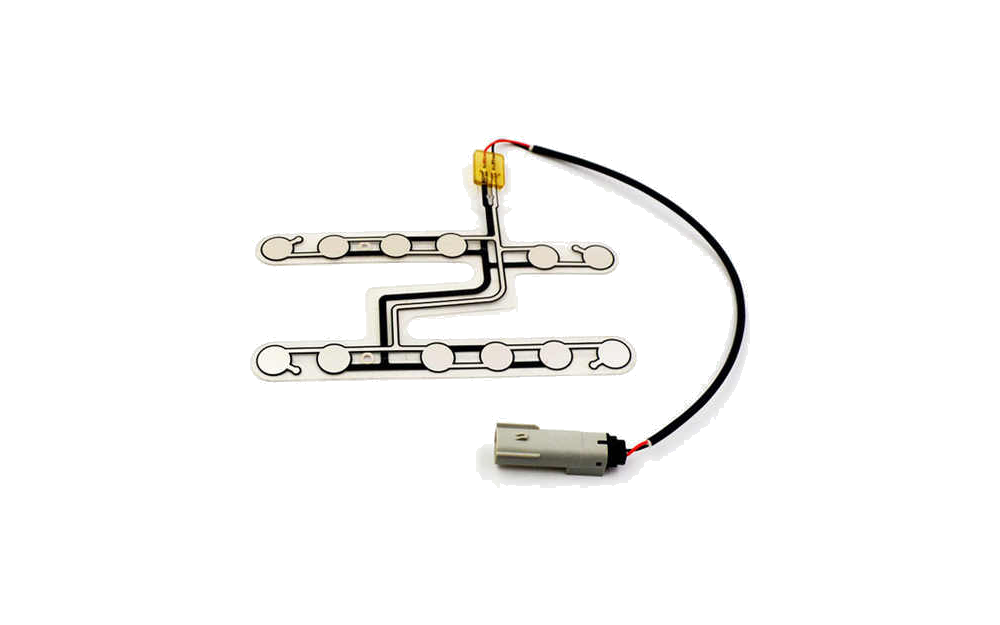
Compare all pressure, membrane, SBR, FSR, passenger, and commercial seat routes.
Review Resource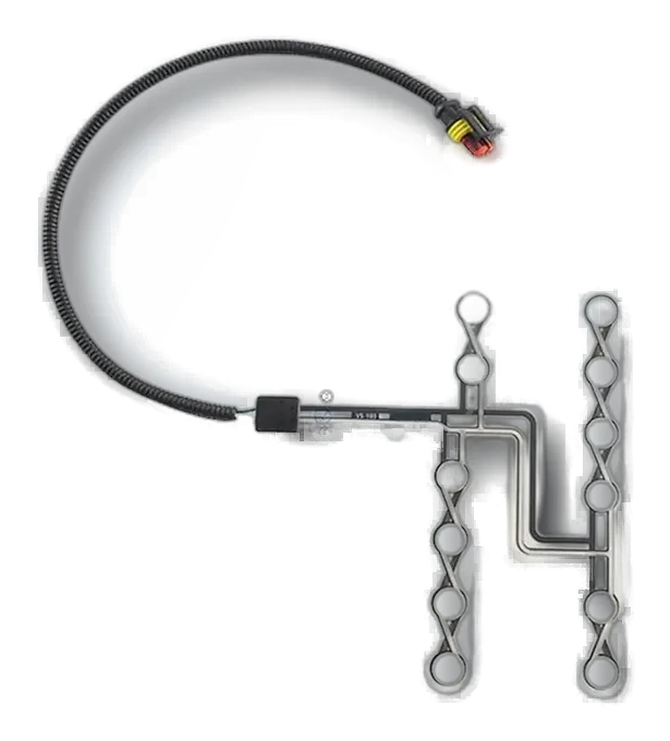
Review physical mat geometry, installation, active zones, and cable exit.
Review Resource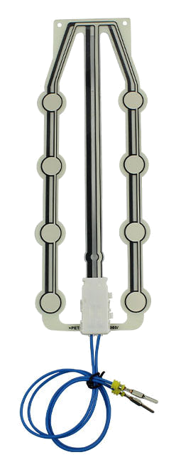
JASPER can review the passenger load zone, sensor structure, installation, interconnect, component evidence, and production controls for the released seat position.
Share the project basics. JASPER will review the stack, materials, connector, quantity, and production risks.