
An engineering comparison of hydrogel and dry medical-electrode interfaces across motion, wear, packaging, electronics, and finished-device validation.
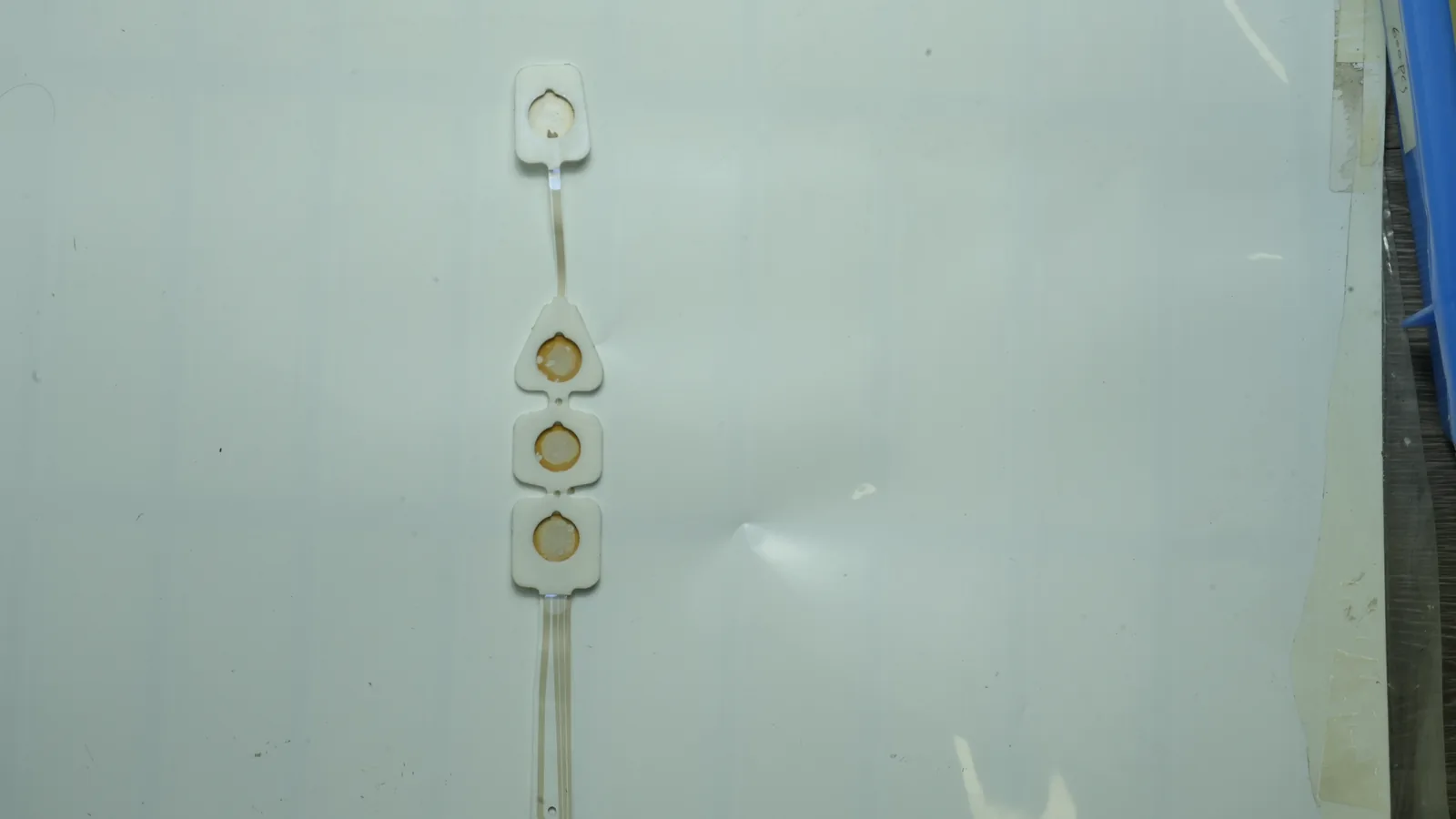
1. Wet vs Dry Electrodes: The Quick Decision
The practical choice is not “best signal” versus “best comfort.” It is which interface can hold its electrical and mechanical state across the intended use. A well-adhered hydrogel electrode can fail after water loss or edge lift. A well-designed dry electrode can outperform a gel control in one fixture yet fail when a garment shifts, hair interrupts contact, or the input stage cannot tolerate interface variation.
| Project condition | Better starting route | Why | What can reverse the choice |
|---|---|---|---|
| Single-use ECG or other adhesive patch; immediate acquisition; trained or guided placement | Hydrogel/wet | Ionic coupling and adhesive fixation can establish a repeatable initial interface | Gel dehydration, residue, edge lift, skin response, or package aging |
| Repeated self-application; no gel cleanup; electrode integrated into a strap or garment | Dry contact | Avoids an applied gel and can support reusable mechanics | Uncontrolled pressure, motion, sweat, coating wear, or cleaning damage |
| Small EEG signals through hair; subtle ERP or low-frequency endpoint | Usually wet or semi-dry first | Wet systems remain a strong reference for low-noise scalp coupling | A validated active dry system may meet the named endpoint and workflow |
| Wearable ECG on relatively hair-free skin with stable compression | Dry contact may be viable | Larger signal and controlled placement can make gel-free acquisition practical | Whole-body movement, garment relaxation, anatomy, or sweat changes contact |
| Extended adhesive patch with moisture-barrier packaging available | Hydrogel can remain viable | Soft, conformal coupling need not mean short wear | The exact gel, adhesive, backing, seal, and labeled duration still need aging and wear evidence |
| Reusable clinical electrode | Dry contact may be viable | No consumable gel layer at each application | Reprocessing efficacy, coating loss, electrical drift, and service-life controls |
| The project cannot define motion, wear, anatomy, front-end, or acceptance criteria | Neither | Material selection cannot repair an undefined test condition | Freeze the use and signal-validation conditions before choosing |
A wearable biosensor patch may use either route. The product architecture—not the word wearable—settles the choice. If the patch is disposable and adhesive, hydrogel may be entirely appropriate. If a reusable garment supplies stable pressure, a dry contact may remove gel handling. If neither interface stays stable, a semi-dry reservoir or a soft self-adhesive dry material may deserve a separate feasibility build.
When the recommended construction is not the best choice
Hydrogel is not the best choice when the required package cannot control moisture, residue is unacceptable, or repeated donning would consume a disposable electrode. Dry contact is not the best choice when the product cannot control pressure and movement, when rigid contacts create unacceptable local load, or when the acquisition electronics and algorithm have not been designed for a higher or more variable interface impedance.
2. What “Wet,” “Hydrogel,” “Dry,” and “Semi-Dry” Mean
A medical electrode skin interface is a stack, not a dot on a drawing. The electrode conductor, ionic or mechanical coupling, stratum corneum, retention method, lead path, amplifier, and algorithm all shape the observed waveform. Chi, Jung, and Cauwenberghs’ methodological review and Li et al.’s 2020 dry-electrode review describe distinct electrical models for wet, dry-contact, and insulated/capacitive interfaces (Chi et al., 2010; Li et al., 2020).
Wet or hydrogel interface
In this article, a wet electrode uses an ionic medium—conductive paste, saline, liquid electrolyte, or water-containing hydrogel—between an electronic conductor and skin. Disposable ECG/EKG electrode patches often combine Ag/AgCl, a conductive gel or hydrogel, a pressure-sensitive adhesive or conductive adhesive, a backing, and a moisture-control pouch. “Wet” does not mean visibly liquid, and hydrogel properties differ by chemistry and grade.
body-facing side
skin
conductive hydrogel / paste / saline
Ag/AgCl, carbon, metal, or printed conductor
printed trace / snap / lead-wire junction
cable or wearable electronics
analog front end → filtering → algorithm
outside world
The electrolyte fills microscopic gaps and changes ionic-to-electronic charge transfer at the interface. Adhesive or a separate carrier can also restrain movement. Those two functions—electrical coupling and mechanical fixation—must be specified separately. A low-impedance gel with poor edge stability can still generate unusable data.
Dry-contact interface
A dry-contact electrode is applied without an added conductive gel or paste. The conductor may be stainless steel, silver, platinum, conductive polymer, silicone, foam, textile, or a pin/comb geometry. A dry electrode may still use a nonconductive adhesive ring, garment, strap, headset, or elastic fixture. “Dry” therefore does not mean adhesive-free, pressure-free, or reusable by default.
body-facing side
skin / hair / incidental sweat film
direct conductive contact, microcontacts, or capacitive gap
metal / polymer / silicone / textile / printed conductor
controlled fixture or skin adhesive
short trace, active buffer, or high-input-impedance front end
filtering → artifact handling → algorithm
outside world
Sweat and humidity can turn a nominally dry interface into a time-varying, weakly electrolytic one. Pressure changes real contact area. A front end that works with one electrode area and one body location may not tolerate another. This is why a wearable dry electrode must be evaluated as a coupled mechanical-electrical system.
Semi-dry boundary
Semi-dry designs meter, retain, or replenish a small quantity of electrolyte. Xue et al. Reported a two-layer hydrogel EEG research electrode with a conductive layer and a substrate-adhesive layer; it was compared with wet paste and dry pins over a 12-hour experiment (Xue et al., 2023). Semi-dry can be a sound third feasibility route when conventional paste is too messy and direct dry contact is too unstable.
One terminology warning matters in procurement: some suppliers contrast “dry hydrogel” with “wet hydrogel.” That describes gel formulation and processing, not necessarily a gel-free dry-contact electrode. The RFQ should name the actual interface stack rather than rely on the word dry.
3. Wet vs Dry Electrodes: Engineering Comparison Matrix
The hydrogel electrode vs dry electrode choice changes across nine coupled dimensions. No row below is a category-wide performance claim; each identifies the mechanism and the evidence an OEM must request.
| Dimension | Hydrogel / wet interface | Dry-contact interface | Decision boundary |
|---|---|---|---|
| Initial coupling | Ionic medium usually fills surface gaps quickly | Contact area may grow during settling, pressure, or perspiration | Define time to usable signal, not impedance at one convenient time |
| Motion control | Adhesive and compliant gel can restrain relative motion | Fixture stiffness, pressure, conformity, friction, and cable restraint dominate | Test intended movement and support structure |
| Interface impedance | Often lower initially for conventional designs | Often higher and more variable, but engineered soft dry designs can reverse this in a named test | Match frequency, area, method, front end, and time point |
| Signal context | Established reference for ECG and laboratory EEG workflows | Viability improves with larger signals, active buffering, short traces, and stable mechanics | Validate the actual ECG/EEG/EMG endpoint and algorithm |
| Wear drift | Water loss, gel migration, edge lift, or skin response can change the interface | Pressure relaxation, sweat, polishing/oxidation, coating wear, or electrode shift can change it | Record signal and interface state through full intended duration |
| Application / cleanup | Liner removal, placement, possible residue and disposal | No applied gel; may need careful alignment or fixture adjustment | Compare total workflow, not application seconds alone |
| Comfort | Soft gel and broad adhesive can distribute load; chemistry and removal still matter | Soft conformal contacts may be comfortable; pins or high pressure may not be | Assess local pressure, removal, heat, sweat, and duration with intended users |
| Storage / packaging | Moisture-sensitive chemistry and liners make barrier package and seals critical | No gel dry-out, but coatings, elastomers, adhesives, oxidation, and cleanliness still age | Establish finished-device aging for the actual package |
| Reuse | Common adhesive patches are single-use, though the category is not inherently so | Frequently considered for reuse | Validate cleaning, disinfection, coating durability, electrical drift, and maximum cycles |
| Validation burden | Gel grade, adhesive, backing, conversion, package, aging, and biological safety | Mechanics, electronics, cleaning, durability, contact pressure, and biological safety | Burden shifts; it does not disappear |
Static impedance is not the verdict
A single impedance value without test frequency, electrode area, pair/single-electrode method, pressure, skin preparation, body location, settling time, humidity, and front-end input is weak evidence. In Mathewson, Harrison, and Kizuk’s N=8 EEG comparison, active dry electrodes recovered conventional spectral and P3 effects, but single-trial RMS noise was approximately 44–46% higher than the two wet systems in that setup (Mathewson et al., 2017). The result does not say every dry electrode needs the same number of trials. Endpoint sensitivity and the noise budget belong in selection.
The opposite result is possible with a different construction. Zhang et al.’s self-adhesive PEDOT:PSS/waterborne-polyurethane/D-sorbitol dry research electrode measured 82 kΩ·cm² at 10 Hz, compared with 148 kΩ·cm² for its commercial gel control, and retained ECG features during the paper’s movement protocol (Zhang et al., 2020). That study refutes “dry always has higher impedance.” It does not establish a general dry-electrode advantage.
Motion is a mechanism chain
Motion artifact can include skin-deformation potential changes, electrode-interface potential shifts, varying contact area and impedance, frictional charge, cable movement, and saturation or recovery in the front end. De Talhouet and Webster’s 1996 work examined skin-stretch artifact mechanisms, while Cömert and colleagues showed that support structure can alter artifact behavior (de Talhouet & Webster, 1996; Cömert et al., 2015). A project that tests only a stationary subject has not evaluated a wearable motion interface.
Electronics change the material verdict
A dry-contact design may require a high-input-impedance front end, low input noise/current, high common-mode rejection, balanced channel impedances, short unshielded paths, and recovery behavior suited to contact interruptions. A hydrogel design can still fail through DC offset, gel/electrode chemistry, cable motion, or poor common-mode control. The electrode coupon and analog front end should be prototyped together.
4. Where a Hydrogel Electrode Wins—and Where It Does Not
A hydrogel interface is the stronger starting candidate when an adhesive patch must produce a usable signal immediately and hold the electrode against skin without a separate garment or fixture. This often fits disposable ECG monitoring, controlled diagnostic acquisition, and other products where a known gel/electrode chemistry and single-use package simplify the use workflow.
Immediate, conformal coupling
A soft ionic medium bridges microgaps that a rigid dry contact would leave open. In Meziane et al.’s simultaneous 24-person ECG comparison, the broad signal-to-artifact order during controlled daily-life movements was Ag/AgCl gel, titanium, silver, stainless steel, then conductive rubber (Meziane et al., 2015). The gel result reflects that electrode geometry, compression shirt, locations, movement set, and signal-processing method—not an eternal ranking.
Adhesive fixation without a separate fixture
A disposable patch can combine the electrical interface and retention system in one converted assembly. That is useful when the wearer cannot be expected to adjust a strap or maintain a prescribed force. It also allows the adhesive footprint, gel aperture, backing modulus, lead exit, and strain relief to be designed around one anatomy and duration.
Established material and ECG evidence paths
FDA’s ECG-electrode guidance names AC impedance, DC offset voltage, combined offset instability/internal noise, defibrillation-overload recovery, bias-current tolerance, adhesive performance, shelf life, and labeling as relevant areas for its ECG scope (FDA, 2011). ANSI/AAMI EC12:2000/(R)2015 is partially recognized by FDA for disposable ECG electrodes, recognition 3-52; the recognition excludes its pre-attached-leadwire safety section (FDA standards database). This is a defined evidence path, not proof that a proposed electrode passes.
Why hydrogel may lose
Water-containing gels create handling and aging variables. Liner removal, slitting exposure, dwell before pouch sealing, seal integrity, backing permeability, and opened-pouch behavior can change water content and adhesion. Gel can leave residue, spread, lift at an edge, or interact with adhesive and skin. A single raw-gel certificate cannot represent the finished patch after conversion and aging.
Hydrogel also loses when repeated self-application is central and a fresh disposable contact is economically or operationally unacceptable. It may lose when hair makes adhesive placement impractical, when residue disrupts the workflow, or when the intended exposure cannot be supported by the selected gel/adhesive biological-evaluation evidence.
5. Where a Wearable Dry Electrode Wins—and Where It Does Not
A dry-contact interface is strongest when gel-free repetition, rapid reuse, or integration into a mechanically controlled product is part of the architecture. Textile shirts, elastic chest straps, headsets, molded wearables, and reusable hand-contact devices can all make dry contact feasible—but each supplies a different force, area, motion path, and cleaning burden.
Repeated application without conductive-gel handling
A user can apply a dry contact without opening a moisture-barrier pouch or cleaning an applied gel after every session. That advantage is real for repeated measurement. It does not eliminate setup: the user may still need to align a garment, separate hair, adjust a headset, tension a strap, or wait for contact to settle.
Joutsen et al. Tested five dry materials during a 10-minute settling study and intermittent measurements to 48 hours. Interface impedance fell and SNR improved during settling; controlled movement reduced SNR, and solid materials generally performed better than porous ones in that fixture (Joutsen et al., 2024). There was no wet control. The useful lesson is that dry material, time, movement, and fixture must be recorded together.
Integration with a garment, strap, or molded support
A fixture can provide repeatable normal force, restrain shear, route the lead, and maintain contact area. Pressure should not be copied from another study as a universal value. Textile-electrode studies demonstrate that impedance and artifact change with pressure and padding, but their preferred ranges are geometry-, anatomy-, and comfort-specific (Cömert et al., 2013; Takamatsu et al., 2019).
No gel-dehydration failure mode
A gel-free contact removes water loss from the coupling layer. That can support repeated or intermittent use. Other drift mechanisms take its place: elastomer creep, strap relaxation, sweat accumulation, oxidation, coating abrasion, textile stretch, laundering, disinfectant exposure, or skin contamination.
Why dry contact may lose
Dry contact is not automatically the better long-wear option. Rigid EEG pins can create local pressure discomfort. A textile electrode can lose force as a garment relaxes. Movement can vary real contact area. Hair, dry skin, perspiration, and anatomy can shift the interface between users. A dry route also loses when the device team expects a passive electrode swap while keeping an analog front end designed around a stable low-impedance gel interface.
For a reusable medical product, cleaning is part of performance. FDA’s reprocessing framework expects validated instructions, and the ECG-electrode guidance requires cleaning and biological decontamination without functional damage. Coating wear, cleaning-agent compatibility, residual soil, post-clean impedance/noise, and the maximum labeled cycle count therefore belong in the verification plan—not in a supplier marketing adjective.
6. Motion, Wear Time, Storage, Packaging, Residue, and Comfort Fail as Chains
Wet and dry electrodes fail through chains of interacting causes. A test should break the chain at the point the product claims to control it.
| Initiating condition | Interface mechanism | Observable failure | Evidence to collect |
|---|---|---|---|
| Cable pull or torso movement | Electrode shear, skin deformation, half-cell/contact change | Baseline shift, transient artifact, amplifier saturation, missed feature | Synchronized motion, raw waveform, recovery time, attachment state |
| Dry-electrode garment relaxes | Lower pressure and real contact area | Rising/imbalanced impedance, noise, intermittent channel | Force/tension, impedance spectrum, SNR, channel yield over wear |
| Perspiration reaches dry contact | Ionic film and friction change over time | Initial improvement or later bridging/slip; user-to-user spread | Sweat condition, time series, nearby-channel isolation, motion state |
| Hydrogel loses water | Conductivity, tack, and modulus drift | Higher impedance/noise, edge lift, incomplete adhesion | Water loss proxy, seal integrity, electrical and peel/edge metrics after aging |
| Hydrogel migrates or spreads | Interface geometry changes | Bridging, residue, reduced effective adhesive area | Dimensional inspection, residue method, adjacent-channel isolation |
| Reusable coating wears | Surface chemistry/roughness changes | Impedance drift, particles, corrosion, cleaning sensitivity | Microscopy, resistance, electrochemical/electrical tests, particulate/chemical risk |
| Adhesive or rigid contact loads skin | Occlusion, chemical exposure, pressure concentration | Discomfort, erythema, early removal, data loss | Human-factors protocol, skin observation, local pressure, removal condition |
| Pouch or seal is inadequate | Moisture exchange or contamination | Out-of-spec gel/adhesive/electrical behavior before use | Package integrity, barrier specification, real-time aging, transport conditioning |
Wear time is an output, not a material label
A “long-wear hydrogel” or “long-term dry electrode” statement is incomplete without the body site, skin condition, movement, temperature, humidity, bathing/water exposure, backing, fixture, lead mass, reuse state, signal endpoint, and acceptable skin response. Xue et al.’s 12-hour hydrogel EEG experiment and Joutsen et al.’s intermittent 48-hour dry study demonstrate useful designs under named protocols; neither supplies a universal labeled wear duration (Xue et al., 2023; Joutsen et al., 2024).
Packaging belongs in the electrical specification
Axelgaard’s AG635 bulk sensing-hydrogel TDS gives a concrete mid-to-upper planning example within the supplier’s 0.6–1.0 mm AG600 sensing-gel series: 0.9 ± 0.1 mm thickness, maximum 500 Ω·cm volume resistivity, pH 3.5 ± 0.5, and bulk-roll shelf life of 12 months non-slit or 6 months slit under its stated conditions (Axelgaard AG635 TDS). It directs users to retain liners and original packaging and distinguishes optimal long-term storage of 5–27°C from short-term conditions. Those are AG635 raw-material planning values, not released JASPER or finished-patch specifications.
Residue and comfort need methods
“Clean” and “comfortable” are not binary material properties. Define residue by a visual grade, recovered mass, surface coverage, or interference with the next workflow step. Define comfort by body site, local pressure, duration, heat, moisture, removal, and user population. Small research studies can generate hypotheses, but an OEM claim needs the intended construction and users.
7. Build the Validation Matrix Before Freezing the Interface
The strongest selection process runs wet and dry candidates through the same intended-use matrix. It does not force identical acceptance numbers where mechanisms differ; it keeps the signal endpoint, body state, and decision rule comparable.
| Evidence layer | Conditions to vary | Measures | Wet-specific checks | Dry-specific checks | Approval boundary |
|---|---|---|---|---|---|
| Material / coupon | Frequency, area, pressure, temperature, humidity, settling | Impedance spectrum, offset, noise, resistance, adhesion/cohesion | Gel thickness, water content proxy, migration, liner compatibility | Surface resistance, coating adhesion, oxidation, compression set | Screens materials only |
| Converted electrode | Lead/snap, backing, die-cut, adhesive, cable strain | Pair impedance, DC offset, internal noise, continuity, edge lift | Gel aperture/fill, lamination exposure, pouch dwell | Fixture interface, local force, strain relief | Approves component revision only |
| Benchtop signal chain | Actual AFE, cable, shield, sampling, filters, power states | Raw noise, common-mode behavior, saturation/recovery, channel balance | Gel/electrode chemistry and offset behavior | Input impedance/current margin, buffering, open-contact recovery | Approves electronics-electrode pairing |
| Simulated use | Placement error, motion axes, sweat/water, hair, clothing, temperature | Signal quality, artifact, missed/false features, recovery, channel yield | Edge lift, fluid ingress path, residue | Pressure loss, slip, sweat-film change, intermittent contact | Supports design verification |
| Human wear / usability | Intended users, body sites, duration, donning, activity, removal | Task success, signal endpoint, comfort, skin observation, early removal | Adhesive removal, residue, gel spread | Alignment, pressure comfort, repeated application | Supports use-related claim only |
| Aging / distribution | Real time, justified acceleration, shipping, seal challenge, opened pouch | Electrical, adhesion, package, visual, chemical/biological risk indicators | Moisture loss, gel/adhesive drift, seal integrity | Coating/elastomer/adhesive aging, cleanliness | Supports labeled shelf life |
| Reprocessing | Worst-case soil, cleaner/disinfectant, dry time, maximum cycles | Soil/microbial endpoints, electrical drift, coating/particle condition | Usually not applicable to single-use patch | Cleaning access, disinfectant compatibility, wear | Supports reuse and cycle claim |
| Final device / regulatory | Intended use, classification, applied-part architecture, software/algorithm | Risk controls, essential performance, biological and electrical evidence | Final gel/adhesive/backing/package evaluated | Final contact/fixture/coating/cleaning evaluated | Device manufacturer owns approval |
Electrical validation must match device scope
For ECG electrodes in the United States, FDA’s special-controls guidance and partially recognized ANSI/AAMI EC12 provide a device-specific starting point. Other products need their own classification and standards map. For an active medical electrical system, IEC 60601-1 Edition 3.2 may govern basic safety and essential performance, with the appropriate IEC 60601-2 particular standard selected by intended use (IEC 60601-1 Edition 3.2). A passive electrode component should not be marketed as independently “IEC 60601-1 approved.”
Biological evaluation uses the final exposure, not a material slogan
ISO 10993-1:2025 treats biological safety within a risk-management process, alongside ISO 14971:2019 (ISO 10993-1:2025; ISO 14971:2019). FDA’s 2023 guidance generally expects the final finished device to be represented, with manufacturing and sterilization effects considered where applicable. FDA’s Attachment G shortcut for certain intact-skin materials expressly excludes hydrogels and skin-contact adhesives used to attach electrode pads (FDA ISO 10993-1 guidance).
That exclusion is not a universal instruction to run the same tests on every electrode. It means the biological-evaluation plan must address the actual materials, manufacturing residuals, contact type, cumulative duration, population, and device risk. A supplier’s TDS statement does not automatically cover a converted, aged, sterilized, or differently packaged electrode.
Component manufacturing is not finished-device approval
A converter can control printed conductor geometry, substrate, adhesive, hydrogel placement, die cutting, lamination, lead/snap integration, and selected in-process tests. The legal manufacturer of the finished device owns intended use, risk management, clinical or performance evidence, software/algorithm validation, labeling, biological evaluation, electrical safety, packaging claim, and regulatory submission. The scope must be written into the quality agreement and drawings.
8. Define Wear and Signal-Validation Conditions Before the RFQ
The next step is not “quote wet and dry.” It is a controlled feasibility request that holds use conditions constant and lets the interface construction vary. JASPER can be considered as one component manufacturer for printed and converted electrode assemblies, but the requested scope must identify which layers and tests belong to JASPER and which remain with the finished-device manufacturer.
Drawing and project-input checklist
| Input to freeze | Minimum information |
|---|---|
| Intended function | ECG, EEG, EMG, biosensing, reference/ground, or another named function; recording versus stimulation |
| Signal endpoint | Frequency band, amplitude/morphology feature, acceptable noise/artifact, algorithm input, missing-data rule |
| Body interface | Anatomical site, hair, skin condition, curvature, electrode area/spacing, contact duration, cumulative use |
| Activity | Posture, walking, running, sleep, flexion, cable pull, donning frequency, expected displacement |
| Environment | Temperature, humidity, perspiration, water/cleaner exposure, clothing, nearby electronics |
| Wet candidate | Electrode material, gel supplier/grade, gel aperture/thickness, skin adhesive, backing, liner, package concept |
| Dry candidate | Electrode material/coating, geometry, fixture/adhesive, target force range, cleaning/reuse concept |
| Electrical chain | AFE model or input requirements, lead length, connector, shield/ground, sampling, filters, power states |
| Human factors | Intended user, placement aid, setup time definition, comfort/removal endpoints, foreseeable misuse |
| Evidence and standards | Device classification, target markets, applicable guidance/standards, biological-evaluation plan, aging claim |
| Change control | Controlled material grades, approved alternates, critical dimensions, lot traceability, test ownership |
Natural material routes may include screen-printed Ag/AgCl electrodes or printed carbon electrodes, but conductor chemistry does not by itself decide wet versus dry. Ag/AgCl can appear in a gelled system or a dry coated contact; carbon can work beneath hydrogel or as a direct-contact material.
Sample approval flow
- Freeze the use matrix. Select at least one static state, one intended motion state, one perspiration/water state where relevant, and the full intended wear window.
- Build two controlled candidates. Keep electrode area, lead routing, body site, and acquisition chain as comparable as the mechanisms allow.
- Run coupon and converted-part checks. Record test method, frequency, pressure, settling time, and environmental state with every value.
- Run the actual analog front end. Inspect raw data before algorithmic cleanup; record saturation and recovery after contact disruption.
- Complete representative simulated use and wear. Include placement variation and expected user behavior, not a single ideal placement.
- Age and reprocess the right product. Hydrogel candidates need final-package evidence; reusable dry candidates need cleaning and durability evidence.
- Approve a controlled stack. Link drawing revision, bills of material, supplier grades, process window, inspection method, and acceptance criteria.
- Transfer to finished-device validation. Keep component approval separate from biological, electrical, clinical, usability, software, and regulatory approval.
A quality and testing reviewshould assign each method and acceptance criterion to an evidence owner before tooling or pilot production. That fulfills the usefuldefine the wear and signal-validation conditions, then ask suppliers to build against them.
9. Frequently Asked Questions
Are wet electrodes always more accurate than dry electrodes?
No. Conventional gel electrodes often provide lower initial impedance and strong signal quality, but accuracy depends on the electrode, fixture, body site, motion, front end, algorithm, and endpoint. One N=8 EEG study found more noise with active dry electrodes; Zhang et al.’s 2020 soft dry prototype measured lower 10-Hz contact impedance than its gel control. Neither result is universal.
What is the difference between a hydrogel electrode vs dry electrode?
A hydrogel electrode uses a water-containing ionic layer to couple the electronic conductor to skin and may also use that layer for adhesion. A dry-contact electrode is applied without conductive gel or paste, but it may still need a strap, headset, garment, or nonconductive adhesive. “Dry hydrogel” supplier terminology should not be confused with gel-free dry contact.
Is a wearable dry electrode better for long-term monitoring?
Not automatically. Dry contact avoids gel dehydration and cleanup, which helps repeated use. Long-term performance can still drift through pressure relaxation, sweat, movement, oxidation, coating wear, garment stretch, or cleaning. Hydrogel can support extended wear when the gel, adhesive, backing, body site, and barrier package are validated for the labeled duration.
Which electrode type handles motion better?
The construction that minimizes relative motion and recovers acceptably in the intended signal chain handles motion better. In Meziane et al.’s 24-person ECG fixture, gel led four tested dry materials in signal-to-artifact ratio. Other engineered conformal dry prototypes have performed strongly under their named motion tests. Test the actual attachment, anatomy, movement, cable, and front end.
Do dry electrodes need special electronics?
Often. Higher or less balanced interface impedance can increase sensitivity to input current, voltage noise, mains coupling, cable motion, and contact interruption. A dry design may need high input impedance, low input noise/current, active buffering near the contact, good common-mode rejection, controlled shielding, and defined saturation recovery. The electrode and analog front end should be approved together.
How should hydrogel electrode shelf life be specified?
Specify the finished electrode and package, not just the bulk gel. Include gel grade, conversion exposure, liner, backing, pouch structure, seal process, labeled storage, transport conditioning, real-time intervals, justified acceleration, and electrical/adhesive endpoints. Axelgaard AG635’s roll shelf life, for example, does not establish the shelf life of a converted pouched patch.
Does ISO 10993 testing by a material supplier approve the finished electrode?
No. ISO 10993-1 frames biological evaluation around the final device, patient contact, duration, manufacturing, and risk. Supplier data can support the assessment, but changes in adhesive, hydrogel, ink, substrate, processing, sterilization, packaging, aging, or exposure may require bridging evidence or new evaluation. The finished-device manufacturer owns the biological-safety conclusion.
What should an OEM send before requesting wet and dry electrode samples?
Send the intended signal and body site, electrode geometry, wear duration, motion and sweat/water conditions, front-end requirements, attachment concept, cleaning or package model, regulatory markets, and measurable acceptance criteria. Ask for controlled material grades and drawings. Without those inputs, two samples may differ in area, pressure, gel chemistry, electronics, and retention—making the comparison unusable.
Technical References
- Source: FDA Use of ISO 10993-1 Biological Evaluation Guidance. Accessed 2026.
- Source: ISO 10993-1:2025 Biological Evaluation of Medical Devices. Accessed 2026.
- Source: ISO 14971:2019 Medical Device Risk Management. Accessed 2026.
- Source: FDA Design Control Guidance for Medical Device Manufacturers. Accessed 2026.
- Source: Chi et al., 2010. Accessed 2026.
- Source: Li et al., 2020. Accessed 2026.
- Source: Xue et al., 2023. Accessed 2026.
- Source: Mathewson et al., 2017. Accessed 2026.
- Source: Zhang et al., 2020. Accessed 2026.
- Source: de Talhouet & Webster, 1996. Accessed 2026.
- Source: Cömert et al., 2015. Accessed 2026.
- Source: Meziane et al., 2015. Accessed 2026.
- Source: FDA, 2011. Accessed 2026.
- Source: FDA standards database. Accessed 2026.
- Source: Joutsen et al., 2024. Accessed 2026.
- Source: Cömert et al., 2013. Accessed 2026.
- Source: Takamatsu et al., 2019. Accessed 2026.
- Source: Axelgaard AG635 TDS. Accessed 2026.
- Source: IEC 60601-1 Edition 3.2. Accessed 2026.
- Source: ISO 10993-1:2025. Accessed 2026.
- Source: ISO 14971:2019. Accessed 2026.
- Source: FDA ISO 10993-1 guidance. Accessed 2026.
Define wear and signal-validation conditions
Send the current drawing, material stack, electrode roles, connector, use conditions, acceptance methods, program phase, and annual volume.