
Define intended use inputs
Document sensing or stimulation function, body-contact type and duration, electrode count, placement, signal or energy conditions, electronics, connector, wear time, storage, packaging, and regulatory owner.
Silver/silver chloride printed electrodes are used when an OEM device needs a defined electrochemical interface and flexible conductor geometry. JASPER supports printing and converting of custom electrode components from released artwork, ink and substrate requirements, contact layout, tail or connector, skin-interface stack, packaging boundary, and inspection plan.
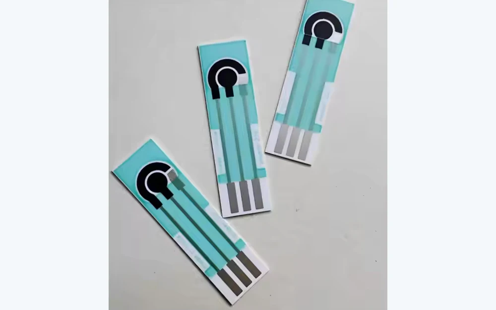
JASPER can manufacture printed Ag/AgCl electrode components for sensing, monitoring, stimulation, wearable, diagnostic, or research-device programs when the customer defines the intended function and finished-device boundary. Ink identity, print thickness, curing, contact geometry, electrolyte or gel interface, skin-contact materials, conductor routing, connector, storage, packaging, and system electronics can all affect measured behavior. Those variables must be controlled in the drawing and validation plan.
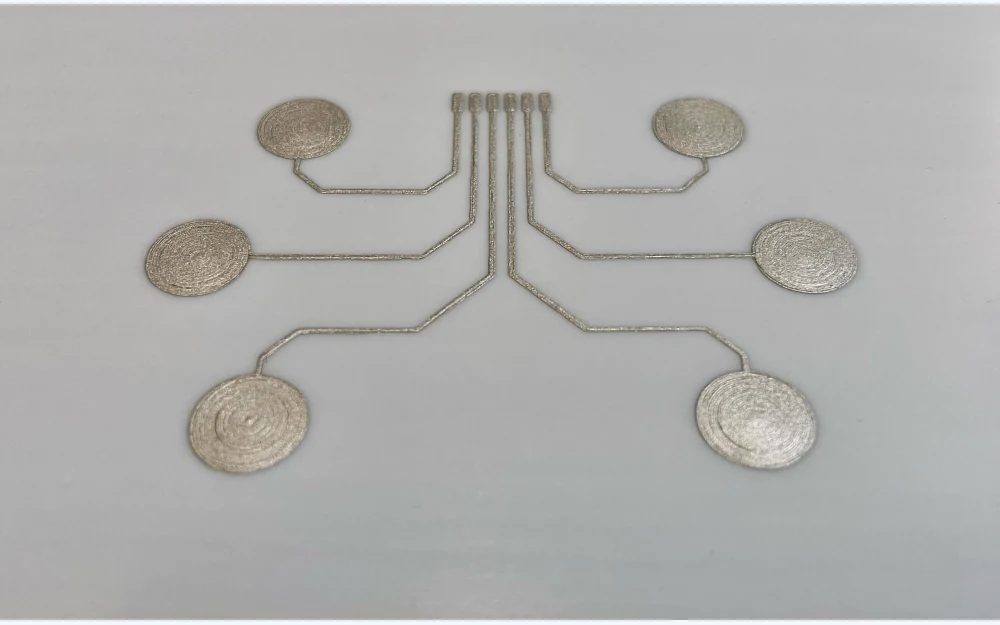
The printed layer is one part of the interface. Each gate keeps chemistry, geometry, conversion, and finished-device responsibility visible.
Document sensing or stimulation function, body-contact type and duration, electrode count, placement, signal or energy conditions, electronics, connector, wear time, storage, packaging, and regulatory owner.
Define substrate, Ag/AgCl and conductor inks, dielectric, contact and trace geometry, print order, cure, tail, connector pads, adhesive, spacer, gel boundary, liner, outline, and datums.
Print, convert, assemble agreed layers, protect the contact zones, and evaluate dimensions, registration, appearance, circuit, connector, interface fit, packaging, and specified electrochemical checks.
Link active files, ink and material lots, process instructions, inspection criteria, approved samples, deviations, changes, protection, packaging, and requested traceability.
Exact values are not universal. They must be supplied or jointly defined for the intended electrode, electronics, interface media, and test method.
| Decision area | Project information | Risk to control |
|---|---|---|
| Printed chemistry | Ag/AgCl and conductor ink identity, print layers, cure, substrate, dielectric, storage and supplier documentation | Drift, unstable interface, poor adhesion, contamination, inconsistent repeat lots |
| Electrode and routing geometry | Contact area, spacing, trace width, shielding, tail, connector pads, datums, registration and keep-outs | Channel mismatch, cross-talk, open circuit, poor fit, misaligned gel or adhesive |
| Skin and electrolyte interface | Gel or hydrogel, adhesive, spacer, liner, body site, contact duration, movement, cleaning and packaging | Dry-out, leakage, lift, irritation risk, motion artifact, edge exposure |
| Verification | Conditioning, fixture, reference electrode, electronics, measured characteristics, sample stage, lot and acceptance owner | A component result being mistaken for finished-device safety or clinical performance |
State which inputs are fixed by the OEM and which require a manufacturing proposal. Do not hide an unknown behind a generic medical-grade label.
It is an electrode component that uses a defined silver/silver chloride print in the contact system, often with printed conductors, dielectric, substrate, adhesive, gel or hydrogel, liner, tail, connector, and converted geometry selected for the intended device.
JASPER can review custom printed electrode arrays and patch components when the OEM supplies the channel layout, intended function, materials, interface stack, connector, packaging, test criteria, and finished-device responsibilities.
No. Biological safety depends on the final finished device, all contacting materials, manufacturing residues, contact type and duration, packaging, storage, and any sterilization. The OEM defines and owns the evaluation strategy.
Include the required electrical or electrochemical characteristics, conditioning, fixture, reference method, sample stage, quantity, lot linkage, format, and acceptance owner. Avoid an undefined request for full medical testing.
Send the artwork, materials, body-contact context, electronics, connector, packaging, quantities, and validation inputs for a component-level feasibility review.
Share the project basics. JASPER will review the stack, materials, connector, quantity, and production risks.