
An HMI panel for water treatment should be specified as a sealed operator-interface assembly, not selected by screen size or a front-face IP label alone. This applies to OEM skids, local wastewater panels, outdoor pump stations, and water-reuse equipment. Start with the actual liquid, chemical, glove, light, temperature, cleaning, and service conditions. Then define the display, touch method, overlay, gasket, panel cutout, connector, enclosure, and corrosion interfaces as one boundary. JASPER's manufacturing scope covers that front-panel hardware; PLC/SCADA programming and process-control logic remain with the controls team.
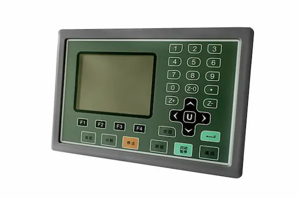
Quick decision table: match the hardware to the exposure
| Project condition | Preferred hardware direction | Acceptance evidence | Common mistake |
|---|---|---|---|
| Dry indoor control room | Panel-mount display or touch HMI with protected rear and service access | Installed fit, functional test, viewing-angle review | Paying for washdown features while ignoring readability and maintenance |
| Splash or routine wet cleaning | Continuous front seal, drained geometry, sealed cutout and rated interfaces | Finished-assembly ingress test using the specified spray direction and duration | Quoting the display's front rating as the cabinet rating |
| Chemical-dosing area | Chemically screened overlay, gasket, adhesive, metals, coating and connector materials | Coupon exposure plus assembled-panel inspection and function test | Treating an IP code as chemical-resistance proof |
| Outdoor or remote cabinet | Sunlight-readable display strategy, UV-resistant face materials, protected rear, condensation plan and field-replaceable connections | Thermal/light review, ingress test, condensation assessment, service trial | Sealing the face while leaving cable exits or the rear electronics exposed |
| Thick gloves or wet fingers | Touch controller and cover stack tuned for the named glove and contaminant; tactile keys for critical actions when needed | Task-based wet/glove test on a production-intent sample | Accepting a generic “glove mode” claim |
| Corrosive wastewater zone | Compatible base metal, fasteners, finish, gasket and connector shell; minimize crevices and liquid traps | Chemical list review, corrosion exposure plan and post-test teardown | Specifying “stainless” without grade, finish, mating metals or exposure |
The weakest interface sets the result. A successful HMI assembly aligns the boundary with use, cleaning, opening, and repair.
A water-treatment HMI is an environmental assembly, not just a touchscreen
A water-treatment HMI is the physical operator interface between plant personnel and the control system. Screen functions are only half the design; manufacturable hardware includes every layer and joint from the operator's finger to the cabinet interior. For foundational terminology, see What Is an HMI Panel? Hardware and OEM Guide.
Panel-mount terminals often protect the front more strongly than the rear. The Siemens SIMATIC technical catalog, for example, lists IP65 at the front and IP20 at the rear for Unified Comfort Panels. The rear still matters. An exposed rear or unsealed cutout defeats bezel-based assumptions.
A production drawing should identify this stack from the wet side inward:
- Graphic surface. A named face material carries legends and takes contact, cleaning, and abrasion.
- Optical interface. Window, antiglare treatment, border, adhesive, and gap or bond affect reflection, haze, and service.
- Touch or switch layer. Capacitive or resistive touch, membrane keys, domes, or discrete controls convert input into a signal.
- Circuit and light. Flex circuits, sensors, LEDs, shielding, tails, and terminations form the electrical layer.
- Structural panel. The carrier sets flatness, stiffness, cutout, grounding, and seal surface.
- Perimeter seal. Gasket or adhesive performance depends on land width, compression, corner radius, surface energy, finish, and process.
- Cable interfaces. Connectors, glands, vents, caps, cable jackets, and strain relief continue the boundary.
- Rear interface. Brackets, door stiffness, service clearance, condensation control, and routing protect electronics.
This layer model complements a broader HMI hardware architecture for industrial automation. It also keeps ownership clear: JASPER can manufacture the front-panel and HMI hardware assembly to released requirements, while the OEM or integrator owns PLC/SCADA behavior and final system acceptance.
Specify an HMI panel for water treatment from exposure outward
The enclosure target follows the exposure definition. “Wet area” is not a test condition. State whether the panel sees condensation, rain, splash, a jet, immersion, or chemical film at a seam. Record direction, distance, duration, frequency, liquid temperature, pressure or flow, and operating state.
IEC 60529 defines the IP Code for degrees of protection provided by enclosures. Its two digits classify access/solid-particle protection and water protection. The code does not, by itself, certify compatibility with sodium hypochlorite, ferric chloride, cleaning agents, ultraviolet light, or a particular corrosion mechanism.
North American projects may also specify a NEMA enclosure type. NEMA's official enclosure guidance describes Type 4X for indoor or outdoor protection against windblown dust, precipitation, splash, hose-directed water, and an additional corrosion level. That does not make “IP66 = Type 4X.” NEMA addresses hazards beyond solids and water, so IP cannot simply be converted upward into a NEMA type.
| Decision | Required project input | Drawing or test output |
|---|---|---|
| Environmental boundary | Which face, edge, rear surface, port and service opening is exposed | Highlighted boundary drawing |
| Liquid challenge | Water/chemical identity, direction, pressure or flow, temperature, duration and frequency | Ingress procedure and acceptance criteria |
| Corrosion challenge | Chemical concentration, vapor or liquid state, temperature, dwell, rinse/dry cycle and cleaning method | Material compatibility matrix |
| Mechanical challenge | Door stiffness, cutout tolerance, fastener torque, vibration source and cable loads | Flatness, torque and strain-relief requirements |
| Operating challenge | Gloves, wet fingers, false-touch risk, target tasks, light and viewing angles | Human-use test protocol |
| Service challenge | Connector unmating, panel opening, field replacement, cleaning and reassembly | Service-state boundary and work instruction |
UL Solutions notes that UL 50 and UL 50E evaluations for enclosure accessories consider corrosion, UV degradation, gaskets, and whether a mounted component maintains the seal. A rated component helps only when installation remains within evaluated conditions. Cutout finish, flatness, clamp location, gasket reuse, and accessories belong in the released design.
Glove operation and alarm visibility must be proven on the complete stack
Touch performance is a system property. Glove mode is conditional. Capacitive response changes with the cover, sensor, display noise, grounding, water film, glove, touch area, firmware, and enclosure. Resistive touch has different optical, wear, and sealing tradeoffs. Tactile keys add feedback, but their graphic, circuit, dome, adhesive, and force still need definition.
Supplier data shows why the exact stack matters. The Microchip mXT1665TD datasheet describes multi-finger operation with a 5 mm glove through 6 mm glass or 3 mm PMMA equivalent, plus compensation for water drops up to 22 mm diameter. It conditions those figures on screen size, touch size, configuration, and stack-up. They cannot be copied into a different assembly without testing.
A wet/glove test should use production-intent samples and actual tasks. Include bare fingers, each glove, droplets at edges, a representative film or residue, grounding states, and cabinet noise sources. Record misses, false touches, unintended multi-touch, acknowledgment success, and recovery after drying. If error creates unacceptable risk, provide a physical control or confirmed action instead of relying on sensitivity tuning.
Alarm visibility also begins with hardware. The display must remain legible at the installed distance, angle, ambient light, and operator height, through the selected overlay texture and any protective window. Reflections, haze, condensation, a deep bezel, small active area, and color shift at oblique angles can hide an otherwise well-designed alarm banner. ISA-101 covers HMI display structures, interaction, graphics, and lifecycle work; the ISA-18 series addresses alarm-system lifecycle management. Those software and operational decisions sit outside front-panel manufacturing, but display size, optical stack, viewing geometry, touch response, and any alarm light or sounder interface must support them.
Sealing succeeds or fails at the perimeter, connectors, and service state
The face sheet is rarely the first leak path. Water tends to exploit a narrow adhesive land, a sharp inside corner, a scratched cutout, a cable that pumps the gland under vibration, a gasket compressed unevenly by a flexible door, or a connector left open during service. Review the seal as a closed path around every opening.
Perimeter seals need geometry and process controls
A pressure-sensitive adhesive can laminate an overlay and help seal a perimeter, but bond data is conditional. The 3M 468MP datasheet, for example, reports a 130 µm firm acrylic adhesive and 7.6 N/10 mm adhesion to stainless steel under ASTM D3330. It marks the data as not for specification purposes and excludes continuous immersion. Check substrate, finish, cleaning, application pressure, dwell, temperature, chemical contact, edge exposure, and continuous load.
Avoid routing the seal across weld spatter, fastener heads, coating steps, embossed features, or a cutout burr. Give the gasket a continuous land. Define compression stops when over-compression can extrude or damage the seal, and locate clamps close enough to control local deflection without loading the display glass. A serviceable door gasket and a permanently bonded display gasket may need different materials and qualification because one is repeatedly recompressed and the other is not.
Connectors are sealed only in their rated configuration
Connector callouts must identify the complete pair, bulkhead seal, mating torque or latch state, cable construction, and unused-port closure. The TE Connectivity M12 X-coded connector, for example, states that final closing produces IP67 environmental shielding, with IP68 optional. The claim depends on completing that specified construction; it does not make every M12 connector waterproof.
Place connectors where a technician can see, mate, and inspect them without twisting cable or damaging the gasket. Strain-relieve flex tails, solder joints, and bulkheads. Service changes the boundary. If protection must remain while a peripheral is removed, specify a tethered cap or a different boundary. NEMA's enclosure FAQ limits the field assembly to its least severe component rating.
Corrosion control requires a material-pair review
Water and wastewater plants do not present one chemical environment. A drinking-water skid, a ferric-chloride dosing panel, a sodium-hypochlorite room, an outdoor lift station, and a sludge-dewatering area expose hardware differently. The U.S. EPA's chlorine-disinfection guidance identifies chlorine forms as corrosive, and its small-system fact sheet notes that hypochlorites are corrosive to most common metals. Convert the site's chemical inventory into a compatibility review; never label a generic “chemical-resistant HMI.”
For every exposed interface, list the base metal, alloy grade, coating, fastener, connector shell, gasket, adhesive, overlay, ink system, and edge condition. The Outokumpu Supra datasheet places 316/316L in a range for highly corrosive environments, but it does not promise resistance to every chloride, hypochlorite concentration, crevice, temperature, or cleaning cycle. Standing liquid, damaged passivation, heat tint, crevices, and dissimilar metals can move failure to the joint.
Condensation is different from external ingress
An outdoor cabinet can pass a spray test and still collect internal moisture. Solar heating, cold rain, night cooling, internal power dissipation, and daily temperature swings change internal pressure and surface temperature. Moist air condenses when a surface falls below its dew point. A correctly selected heater, drain strategy, thermal design, or breathable vent may be needed; the choice belongs to the enclosure-level analysis.
The Gore protective-vent FAQ explains that a bidirectional ePTFE vent can equalize pressure and let water vapor leave, reducing trapped condensation while blocking specified contaminants; it also says condensation cannot be eliminated completely. Select a vent for enclosure volume, pressure-change rate, contaminant exposure, placement, airflow, and ingress performance, then test the cabinet. Additional patterns appear in Rugged HMI Design for Harsh Environments.
The application-risk matrix should drive the HMI architecture
The same water utility may need several HMI constructions. Use the matrix to identify dominant risks before selecting the display or touch technology.
| Application zone | Dominant hardware risks | Architecture direction | Validation emphasis |
|---|---|---|---|
| Central control room | Glare, long viewing sessions, dense information, service downtime | Larger readable display; protected rear; maintainable panel mount | Viewing distance/angle, thermal operation, connector access |
| Packaged filtration or RO skid | Splash, cleaning, vibration from pumps, tight cutout | Sealed face and cutout; restrained cables; compact service envelope | Installed ingress, vibration with actual mounting, glove tasks |
| Chemical-dosing cabinet | Corrosive liquid/vapor, residue at seams, glove use | Screened face materials; minimal crevices; sealed connections; tactile fallback where risk requires | Named-chemical exposure, teardown inspection, wet/glove false-touch test |
| Outdoor pump or lift station | Rain, sun, condensation, temperature swing, infrequent service | Outdoor optical strategy; UV-stable face; protected rear; vent/heater/drain analysis | Solar/light review, thermal cycle, spray, condensation, field replacement |
| Water regeneration or reuse system | Mixed indoor/outdoor exposure, disinfectants, frequent status/alarm review | Zone-specific stack rather than a single plant-wide default | Chemical list, alarm visibility, cleaning cycle, common-spares review |
The recommended front-panel assembly is unsuitable when the environment requires a listed hazardous-location product, hygienic certification, sanitation beyond the defined test, continuous submersion, or a safety function dependent on uncertified touch. It also fails the fit test when the rear cannot be enclosed or technicians cannot restore the seal. Change the boundary: use a fully enclosed terminal, relocate the HMI, add a viewing window and external controls, or select a purpose-certified assembly.
Validation must reproduce installation, contamination, and maintenance
A component certificate is an input, not the final result. Test the real assembly. Build the plan from the boundary drawing with production-intent hardware, seal, connector, cable, torque, firmware, and process. The HMI Panel Assembly Design Checklist organizes drawing review; testing and validation planning connects each requirement to evidence.
| Test block | Conditions the project must define | Practical acceptance evidence |
|---|---|---|
| Ingress | Orientation, spray/jet/immersion method, duration, liquid temperature, operating state | No unacceptable ingress; functional test; internal inspection |
| Chemical exposure | Chemical name, concentration, temperature, dwell, number of cycles, rinse/dry method | No loss of legend, swelling, cracking, delamination, corrosion, seal damage, or functional change beyond limits |
| Touch and gloves | Glove models, contaminants, droplets/film, grounding, screen tasks, noise sources | Defined miss/false-touch limits and successful completion of critical tasks |
| Optical performance | Ambient light, viewing distance/angles, condensation state, protective films removed | Alarm and status information remain readable from required positions |
| Mechanical | Installed cutout, support stiffness, cable loads, mounting orientation, specified vibration/shock severities | No loosening, cracked glass, intermittent connection, seal migration, or unacceptable display/touch change |
| Thermal/condensation | Operating/storage temperatures, humidity, power state, solar load, transition rate | No trapped moisture or functional/material degradation outside acceptance limits |
| Service | Opening count, connector cycles, cleaning, gasket replacement/reuse rule, technician tools | Seal can be restored and verified without hidden damage |
IEC 60068-2-6 and IEC 60068-2-27 provide standard methods for sinusoidal vibration and shock. They do not select the severity for a pump station or dosing skid. The OEM must supply axes, mounting, waveform or pulse, level, duration, operating state, and post-test acceptance criteria.
During prototyping and sample approval, inspect seal continuity, overlay registration, window cosmetics, connector access, flex-tail strain relief, torque, bezel deflection, touch behavior, and restoration after service. Record the approved assembly state for production and incoming inspection.
Frequently asked questions
What IP rating should an HMI panel for water treatment have?
There is no universal IP rating for water treatment. Specify the actual exposure—condensation, splash, rain, water jet, or immersion—then choose and test the complete installed assembly to the relevant IEC 60529 condition. Record which surfaces and service states are protected; a front-face rating does not automatically cover the rear, cutout, connectors, or cabinet.
Is IP66 equivalent to NEMA Type 4X?
No. IP66 addresses dust and powerful water jets under IEC 60529, while NEMA Type 4X also includes an additional corrosion-protection dimension and other enclosure conditions. NEMA and IP designations are not interchangeable certifications. State the required system separately and verify the finished enclosure and mounted accessories to that requirement.
Can a capacitive touchscreen work with wet gloves?
It can, but only a tested controller, sensor, cover, firmware, grounding, and display stack can establish performance. Validate each specified glove with dry and wet surfaces, representative droplets or films, cabinet electrical noise, and real tasks. Set limits for missed and false touches; keep critical actions off touch alone when the risk analysis requires a physical control.
What overlay material works near treatment chemicals?
No overlay polymer is universally compatible with treatment chemicals. Select a hardcoated polyester, polycarbonate, glass, or other face material from a matrix that names the chemical, concentration, temperature, dwell, cleaning cycle, and edge exposure. Test printed legends, clear windows, adhesives, and formed features together because failure often begins at an ink, cut edge, or seam.
Does a stainless-steel front panel prevent wastewater corrosion?
Not by itself. Specify the alloy grade, surface finish, passivation condition, fastener and connector materials, coating interfaces, crevices, and drainage. Chlorides, hypochlorite, temperature, deposits, damaged surfaces, and dissimilar-metal contact can attack the joint. Corrosion approval should combine material evidence with assembly-level exposure and teardown inspection.
How should HMI connectors be sealed in a remote cabinet?
Define the mated connector pair, bulkhead seal, cable jacket, strain relief, assembly torque or latch state, and caps for unused or disconnected ports. Place connections where technicians can inspect and remate them without side-loading the cable. The installed protection is limited by the weakest connector, gland, cap, vent, cutout, or enclosure interface.
How can condensation be reduced inside an outdoor HMI cabinet?
Model temperature swings, solar load, internal heat, humidity, dew point, cabinet volume, and pressure change. Depending on the result, use thermal management, drainage, a correctly selected breathable vent, or relocation. Then run cabinet-level transition tests. A high front ingress rating blocks external water under its test; it does not prove that internal condensation cannot form.
What should an OEM provide for an HMI assembly quote?
Provide the display size and model, front-panel drawing and cutout, interface stack, touch or key requirements, connector and tail definition, environmental and chemical exposure, gloves, viewing conditions, validation standard, service method, annual volume, and regulatory destination. Add acceptance criteria and identify which party owns enclosure certification, PLC/SCADA programming, and final system validation.
References
- International Electrotechnical Commission, IEC 60529: Degrees of protection provided by enclosures (IP Code).
- National Electrical Manufacturers Association, NEMA Enclosure Types and NEMA/IP ratings technical bulletin.
- UL Solutions, Environmental-Rated Accessories for Enclosures.
- U.S. Environmental Protection Agency, Wastewater Technology Fact Sheet: Chlorine Disinfection and Disinfection for Small Systems.
- International Society of Automation, ISA-101 and ISA-18 series pages cited above.
- Original supplier data: Siemens SIMATIC ST80 / ST PC 2024 catalog; Microchip mXT1665TD; MacDermid Alpha Autotex XE; 3M 468MP; TE Connectivity M12 X-Code; Outokumpu Supra; and Gore protective vents, each linked where used.
Project-input checklist and engineering handoff
Before releasing an RFQ, send this project package:
- Display manufacturer/model, active area, dimensions, resolution, interface, backlight, viewing direction, rear keep-out, and life requirement
- Dimensioned panel/cutout drawings, material/finish, flatness, radii, tolerances, fasteners, clamp zones, grounding, and rear depth
- Interface stack: overlay/lens, border, touch sensor, optical gap/bond, display, seal, carrier, circuit or keys, shielding, and connector transition
- Operating tasks, critical actions, alarm-presentation area, operator distance/angles, ambient light, each glove model, wet-finger state, and permitted missed/false-touch limits
- Water method and each chemical/cleaner with concentration, temperature, dwell, frequency, rinse/dry cycle, and vapor or liquid state
- Operating/storage temperature, humidity, solar load, condensation, vibration/shock, orientation, cable loads, and service cycles
- Connector pair, bulkhead, pinout, cable length/jacket, tail exit, bend/strain relief, unused-port caps, field mating sequence, and the environmental boundary while disconnected
- Required IEC, NEMA, UL, customer, or destination evidence; test severities; sample size; acceptance limits; inspection method; owner for final enclosure/system approval
- Labeling, traceability, packaging, cosmetic criteria, approval sample, annual volume, forecast profile, and change-control requirements
Use the package to send drawings for engineering review. Include the display size, front-panel drawing, interface stack, environment, and annual volume so the review can separate confirmed inputs from open risks. When the specification and acceptance basis are ready, request an engineering quote.
Project suitability and performance must be established from the released requirements and production-intent validation.
Bring the drawing, stack and operating conditions
JASPER engineering will review the interfaces, open risks and evidence required for a production quote.