
Map the medical electrode layer stack across 5 interfaces: substrate, conductive ink, dielectric, adhesive, and skin—plus testing boundaries.
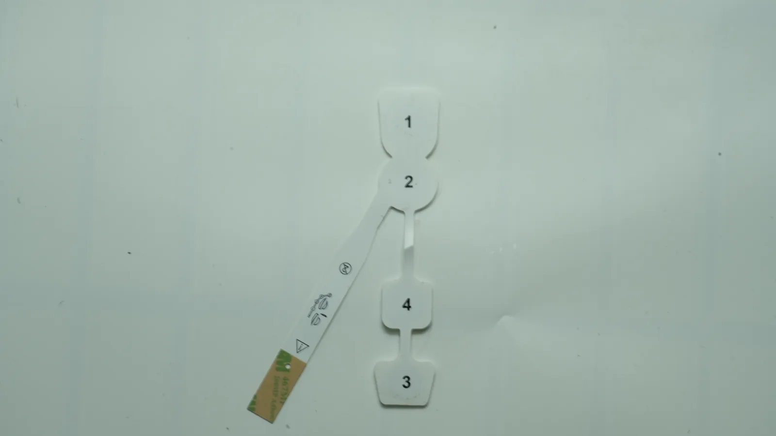
A controlled stack-up lets a converter manufacture the intended article and lets the finished-device team test the right risks. This guide covers flexible, non-invasive printed electrodes and wearable patches. It does not establish biological safety, sterility, clinical performance, shelf life, equipment compatibility, or regulatory approval. Those conclusions depend on the exact finished device, intended use, contact duration, manufacturing process, packaging, and jurisdiction.
1. What a Medical Electrode Layer Stack Includes
The medical electrode layer stack is the controlled arrangement of structural film, printed conductor, electrode-interface material, insulation, adhesive, gel, connector, and release liner that joins a circuit to a body-contacting interface. Some projects buy only the printed circuit; others buy a converted subassembly or packaged electrode. The drawing and bill of materials must identify that supply boundary.
CIRCUIT / OUTER SIDE
Optional backing, cover film, stiffener, or electronics
Printed electrode substrate: PET, TPU, PI, or other film
Printed conductor: trace, bus, contact pad, electrode area
Patterned dielectric: covers traces; leaves windows exposed
Optional connector, snap, tail, lead, or conductive bond
Exposed electrode · Perimeter skin adhesive / carrier
conductive gel, · (if separate from the gel)
hydrogel, or dry face
Release liner removed immediately before application
PATIENT / SKIN SIDE
This cross-section separates four jobs: electronic conduction in the trace, ion-to-electron transfer at the active interface, mechanical attachment, and insulation of regions that should not contact skin. A 2024 ACS Nano paper reported a wet ECG design with a plastic substrate, printed silver-nanowire conductor, electrode gel over the conductive region, and adhesive gel around it. That construction shows how functions can be printed separately; its reported performance does not transfer to another patch (ACS Nano, 2024).
The JASPER electrode-pad product family is relevant when a requirement involves a printed circuit or converted electrode assembly. A project must still define whether the quoted scope stops after printing, after lamination and die cutting, or after skin-contact integration. “Electrode pad” does not answer that question.
Layer-function decision table
| Layer or interface | Main function | Typical options—not equivalents | Required inputs | Failure if left vague |
|---|---|---|---|---|
| Backing or outer cover | Carries and protects the patch | Foam, nonwoven, PET, TPU, polyurethane film | Grade, thickness, edge geometry, moisture exposure | Lift, wrinkling, trapped moisture |
| Printed electrode substrate | Holds registration through print, cure, lamination, and flex | Heat-stabilized PET, TPU, polyimide | Grade, treatment, orientation, cure exposure, dimensional limit | Misregistration, cracking, curl |
| Conductor/electrode ink | Carries electrons and forms the intended active interface | Silver trace, Ag/AgCl, carbon, other application-specific systems | Grade/formulation, cured thickness, geometry, cure, test method | Open circuit, drift, polarization |
| Printed dielectric | Protects traces and defines exposed windows | UV- or thermally cured polymer dielectric | Grade, cured thickness, overlap, window, registration | Leakage path, exposed trace, blocked electrode |
| Assembly adhesive | Bonds internal layers | Transfer adhesive, double-coated tape, heat-activated film | Substrates, thickness, bond area, lamination conditions | Tunneling, squeeze-out, delamination |
| Skin adhesive | Secures the device to a defined site | Acrylic, silicone, hydrocolloid, adhesive hydrogel | Exact grade, site, contact duration, removal criteria | Early lift, residue, skin trauma |
| Conductive interface | Couples ionic current between skin and electrode | Wet gel, conductive hydrogel, dry face | Grade, area, thickness, water-loss control, electrical method | Unstable interface, drying, motion artifact |
| Connector/contact | Transfers signal or energy | Snap, tab, printed tail, leadwire, conductive bond | Mating geometry, strain relief, contact finish, flex zone | Intermittency, trace fracture |
| Release liner | Protects adhesive and gel before use | Coated paper or polymer | Grade, release side/value, split/tab geometry | Gel loss, transfer, difficult placement |
2. Specify the Printed Electrode Substrate as a Process Material
A printed electrode substrate is not adequately defined by “PET.” The film must survive the selected ink solvent, drying or UV exposure, registration sequence, lamination pressure, die cutting, handling, and final bending. Its treated surface must also support the actual conductor and dielectric system.
Heat-stabilized PET is a common baseline where dimensional registration and economical screen printing matter more than high stretch. Tekra lists Melinex ST506 as a two-side-treated PET for silver conductive and dielectric inks in 125, 175, and 250 μm grades. Tekra's stabilized-film brochure reports less than 0.1% machine- and transverse-direction shrinkage after 30 minutes at 150°C unless otherwise noted (Tekra ST506; Tekra film brochure). That is a grade-specific supplier condition, not a universal registration tolerance.
TPU or another elastomer becomes relevant when the electrode must follow substantial body strain. This choice adds print elongation, modulus mismatch, post-strain recovery, liner stability, and adhesive constraint to the design. Henkel LOCTITE ECI 1014, for example, is marketed as a stretchable silver ink for PET, TPU, PI, PEN, and polycarbonate; compatibility still requires trials with the exact film and cure sequence (Henkel ECI 1014).
Polyimide tolerates process temperatures that distort many PET or TPU films, but temperature resistance alone does not make it suitable for a skin-worn patch. Stiffness, cost, edge feel, adhesive compatibility, and the body-contact construction can outweigh its thermal advantage. The wearable biosensor patch route is therefore a related application, not proof that one substrate fits every wearable.
A named grade, nominal thickness and tolerance, treatment side, print side, machine direction, maximum process exposure, artwork datum, and registration acceptance after final cure.
“0.125 mm PET or equivalent” without equivalence criteria for treatment, shrinkage, ink adhesion, or flex behavior.
Substrate selection boundaries
| Requirement | PET starting point | TPU/elastomer starting point | Polyimide starting point | Question that remains open |
|---|---|---|---|---|
| Multi-pass print registration | Often favorable with heat-stabilized grades | Requires carrier/handling and strain control | Often thermally stable | What is the post-process positional tolerance? |
| High conformability or stretch | Limited by film/ink system | Better candidate with compatible stretchable ink | Usually not the softest option | What strain and cycle profile represents use? |
| Elevated cure exposure | Grade-dependent | Often tighter thermal/process window | Higher-temperature candidate | Does every adhesive/gel tolerate the same process? |
| Skin-worn comfort | Depends on thickness and whole laminate | Potentially softer and more conformal | Edge/stiffness require scrutiny | Which body site, duration, and user population? |
3. A Conductive Ink Electrode Is More Than a Silver Trace
The term conductive ink electrode can mean a low-resistance trace, an electrode that exchanges charge with an ionic medium, or a working/counter/reference electrode in an electrochemical sensor. The features may share a print pass, but their electrical and electrochemical jobs differ.
Separate the trace from the active interface
Silver polymer ink is often considered for traces because it can provide comparatively low sheet resistance at a practical printed thickness. The patient-facing interface may instead use Ag/AgCl, carbon, gold, platinum, or another application-specific system. DuPont 5881 identifies a 75/25 Ag:AgCl composition for screen printing on polyester and names ECG/EKG, EMG, EEG, TENS, and EMS among typical applications (DuPont 5881). Henkel EDAG PE 409 E&C is a different 9:1 Ag/AgCl product for polyester-film sensing devices (Henkel PE 409). These chemistries are not interchangeable recipes.
Carbon has another role. DuPont BQ221 is described as a screen-printable carbon composition for working electrodes in high-sensitivity biosensors on PET or polycarbonate (DuPont BQ221). That does not make carbon a substitute for Ag/AgCl in every recording electrode, nor Ag/AgCl correct for every analyte. Selection begins with signal, energy, chemistry, reference architecture, and intended-use risk.
The print specification should control wet or cured deposit thickness, geometry, cure profile, overlap between inks, and the coupon or finished-feature method. Sheet resistance on a rectangular coupon cannot by itself predict electrode-skin impedance, reference stability, stimulation current density, or signal behavior in motion.
Define the dielectric's job
A printed dielectric normally covers traces, protects crossovers, and defines electrode/contact windows. DuPont 5018 is a UV-curable dielectric for flexible circuitry on polyester; its sheet reports breakdown of at least 500 V/mil under the supplier's method (DuPont 5018). Henkel EDAG 452SS E&C is another flexible UV-curable dielectric for polyester and polycarbonate circuitry (Henkel 452SS). Neither value establishes patient isolation or IEC 60601 compliance in a finished device.
Artwork must name grade, cured thickness or print passes, trace overlap, exposed windows, contact openings, registration tolerance, and cure sequence. Inspection can address pinholes, edge coverage, registration, adhesion, and drawing-level isolation. A second meaning appears in capacitive electrodes: an intentional dielectric sits in the body-coupling path. That architecture requires another electrical model; it is not merely protective ink over a trace.
| Design question | Trace conductor | Active electrode material | Printed dielectric |
|---|---|---|---|
| Primary job | Carry electronic current | Exchange or couple charge at the intended interface | Insulate traces and define exposed geometry |
| Key inputs | Width, length, cured thickness, contact geometry, cure | Area, grade, overlap, surface, interface medium | Grade, thickness/pass count, overlap, window, cure, registration |
| Component checks | Continuity, resistance, adhesion, geometry | Area/visual checks plus application-specific method | Coverage, pinholes, adhesion, registration, specified isolation |
| Cannot prove alone | Signal quality, energy delivery, patient safety | Biological safety or clinical performance | Applied-part classification or equipment leakage current |
4. The Electrode Adhesive Stack Has Three Bonding Jobs
An electrode adhesive stack can contain an internal assembly adhesive, a perimeter skin adhesive, and a conductive adhesive hydrogel. Calling all three “medical adhesive” hides different requirements.
The internal adhesive bonds film, backing, stiffener, connector support, or electronics. It must wet the substrates, survive downstream conditioning, and avoid flowing into electrode windows; it may never touch skin. A skin-contact pressure-sensitive adhesive must balance attachment and removal on a defined anatomical site for a defined duration. Solventum treats skin condition, conformability, moisture, breathability, edge design, wear duration, and removal as coupled inputs (Solventum Skin-Contact Layer).
Conductive hydrogel adds ionic coupling and may also provide adhesion. Some designs use one conductive adhesive gel across the sensing area. Others place conductive gel over the electrode and a separate adhesive ring around it, as in the 2024 ACS Nano example. The drawing should show which material touches the exposed electrode, which contacts skin, whether they overlap, and how migration or squeeze-out is controlled.
3M Hydrogel Adhesive 9880 offers a initial supplier benchmark, not a JASPER specification. Its October 2010 sheet reports 0.46 mm thickness without liner, 23% target water content, pH 4.0–5.0, and maximum impedance of 25 Ω/sq in under the listed conditions (3M 9880 TIS). Current availability and values require supplier confirmation. The figures do not predict wear on a body site, biological safety after processing, shelf life in another pouch, or performance with another geometry.
ASTM D3330/D3330M supports controlled peel comparison for pressure-sensitive tape; ASTM D3654/D3654M addresses shear, and ASTM D6195 addresses loop tack (ASTM D3330; ASTM D6195). A result on steel or another standard panel is not a skin-wear claim. A device study must define site, preparation, application pressure, dwell, motion, sweat/humidity, duration, removal rate, residue, edge lift, and skin endpoints.
The liner completes the pre-use package. Release coating, split geometry, peel direction, and storage orientation can affect gel transfer and placement. If liner removal pulls hydrogel from the electrode or forces contact with the sensing area, the failure belongs to the stack.
5. When This Construction Is Not the Best Choice
A PET-based, screen-printed, adhesive-backed wet electrode is not the default answer for every body interface.
- Large or repeated strain: A rigid trace on PET may concentrate strain. A stretchable TPU/ink system, textile electrode, serpentine metal, or another compliant architecture may fit better after mechanical-electrical cycling.
- Repeated reuse: A replaceable dry electrode or mechanically retained sensor may be preferable when gel replacement, residue, or single-use waste conflicts with the use model.
- Implantable, needle, catheter, or mucosal contact: These applications need different materials, cleanliness controls, mechanics, biological endpoints, and regulatory evidence.
- High-energy therapy or electrosurgical return: Current density, thermal distribution, cable safety, monitoring, and application-specific standards dominate. A recording electrode cannot simply be enlarged.
- Electrochemical biosensing: Reagent layers, working/counter/reference geometry, membranes, fluid handling, calibration, and analyte stability may govern the stack.
- Capacitive sensing through clothing or insulation: An intentional coupling dielectric and input electronics replace the wet ionic-interface model.
- Direct-on-skin printed research systems: Removing discrete film or adhesive changes deposition, removal, reproducibility, and validation.
Choose the architecture that supports the intended signal or energy path under expected mechanics and environment. A familiar printed stack should not be retained when one interface creates the dominant risk.
6. Follow the Failure Chain
Failures seen at skin can begin in printing, curing, registration, or assembly. Investigation should follow the chain from design input to symptom.
| Design/process error | Interface defect | Likely observation | Component/assembly check | Finished-device question |
|---|---|---|---|---|
| Substrate shrinks after conductor print | Dielectric window shifts | Reduced active area; unit variation | Post-cure registration and artwork overlay | Does signal/energy performance remain acceptable? |
| Conductor is under-cured or poorly adhered | Trace drifts or cracks in flex | Intermittent channel in motion | Cure record, resistance map, flex test | Does motion cause unacceptable artifact or loss? |
| Ag/AgCl layer or overlap is nonuniform | Local interface varies | Offset, noise, or channel imbalance | Area/thickness inspection; application method | Does the complete electrode meet its protocol? |
| Dielectric has pinholes or short overlap | Conductive region is exposed | Leakage, corrosion, migration risk | Coverage inspection; specified isolation test | Are patient-connection risks controlled? |
| Assembly adhesive enters sensing window | Effective interface area falls | High or unstable interface impedance | Window image/area measurement | Does performance hold across placement and wear? |
| Hydrogel dehydrates in package | Ionic coupling changes | Drift, noise, poor initial contact | Package seal/mass; aged gel property | Is shelf life supported in final packaging? |
| PSA/backing traps moisture | Skin and edge behavior change | Lift, residue, discomfort | Moisture and adhesive characterization | Does wear meet biological and usability criteria? |
| Connector lacks strain relief | Tail creases or contact frets | Intermittency when cable moves | Directional pull/flex test | Is the connected system safe and functional? |
| Liner release is mismatched | Gel or adhesive transfers | Damaged sensing face | Conditioned release and visual inspection | Can users apply the device consistently? |
A continuity threshold belongs to conductor geometry and equipment; peel belongs to a defined method and substrate; impedance belongs to application and frequency; shelf life belongs to final packaging. One supplier's number should not be copied into another stack.
7. Put the Stack-Up on the Drawing Before Samples
The first useful deliverable is a controlled cross-section tied to artwork, BOM, process notes, and acceptance methods—not a loose material list.
Drawing and RFQ checklist
- [ ] Function: recording, stimulation, return, iontophoresis, or electrochemical sensing
- [ ] Body site, user population, skin assumptions, and contact duration category
- [ ] Supplied article: printed circuit, converted subassembly, integrated patch, or packaged electrode
- [ ] Outline, active area, channel count, routing, and keep-out zones
- [ ] Substrate grade, thickness/tolerance, treatment side, orientation, and process exposure
- [ ] Every conductor/electrode ink grade or approved-equivalence definition
- [ ] Cured thickness or print-pass requirement and cure sequence
- [ ] Dielectric grade, overlap, windows, registration tolerance, and contacts
- [ ] Assembly adhesive, skin adhesive, gel/hydrogel, backing, and liner as separate BOM lines
- [ ] Connector/tail/lead geometry, mating interface, strain relief, and flex zones
- [ ] Critical dimensions, datums, edge requirements, and die-cut tolerance
- [ ] Method, conditioning, equipment, sample size, location, unit, and limit for each test
- [ ] Packaging, storage, transport, sterilization exposure if applicable, and shelf-life owner
- [ ] Biological, electrical, wear, usability, and regulatory responsibilities
- [ ] Change notice for material, supplier, site, formulation, tooling, process, or method
Six-step approval flow
- Freeze the boundary. Identify what the article does and what the converter supplies. An exposed-window printed tail differs from a pouched skin-contact device.
- Create the drawing and BOM. Give every functional material an identifier. Do not hide gel, perimeter PSA, or liner in an assembly note.
- Run material-system coupons. Confirm print, cure, adhesion, overlap, resistance, dielectric coverage, and lamination on the exact grades.
- Build representative samples. Include real trace lengths, transitions, windows, edge clearances, connector, backing, and liner.
- Approve component evidence. Record dimensions, registration, visual defects, continuity/resistance, adhesion, flex, and release where specified. Use the quality and testing framework to define evidence for the quoted scope; confirm each actual JASPER test before placing it in a purchase specification.
- Validate the finished device. Integrate representative product with electronics, packaging, labeling, sterilization when applicable, and intended-use conditions.
The approval record should identify drawing and BOM revisions, material lot/supplier reference, process route, conditioning, method, raw results, deviations, and disposition. A photograph without traceable measurements is not a first-article record.
Sample approval checklist
| Evidence package | Review question | Accept only when |
|---|---|---|
| Cross-section and artwork overlay | Are functional layers and exposed regions unambiguous? | Revisions, datums, windows, overlaps, and supply boundary agree |
| Material trace | Were approved grades and lots used? | BOM, supplier record, storage status, and substitutions are documented |
| Process record | Did the build follow the qualified route? | Print/cure/lamination/converting parameters and deviations are traceable |
| Inspection/test report | Does the article meet drawing inputs? | Method, condition, instrument, sample, units, results, and limits are present |
| Representative assembly | Does geometry include actual stress concentrations? | Connector, tail, edge, window, backing, gel, adhesive, and liner match design |
| Disposition and change control | Can the same approved state be repeated? | Deviations are closed and notification triggers are agreed |
8. Component Verification Is Not Finished-Device Validation
A component manufacturer can verify conformance to a printed and converted drawing. It cannot declare the finished device biologically safe, sterile, clinically effective, universally compatible, or regulator-approved.
FDA's ECG-electrode guidance identifies electrical performance, adhesive performance, biological response, shelf life, labeling, and—when claimed—sterility or MRI/radiographic compatibility as device concerns (FDA ECG guidance). ANSI/AAMI EC12:2000/(R)2020 covers disposable diagnostic and monitoring ECG electrodes, not every recording, stimulation, return, or biosensor electrode (AAMI EC12).
ISO 10993-1:2025 places biological-safety evaluation within risk management. FDA categorizes contact duration as limited (≤24 hours), prolonged (>24 hours through 30 days), and long-term/permanent (>30 days) (ISO 10993-1:2025; FDA duration framework). A raw-material datasheet cannot replace evaluation of the processed, contacting finished device.
ISO 14971:2019 remains current after confirmation in 2025 (ISO 14971:2019). IEC 60601-1 Edition 3.2 addresses basic safety and essential performance of medical electrical equipment, not independent qualification of ink or laminate (IEC 60601-1). IEC 60601-2-47:2012 may apply to ambulatory ECG systems at equipment level (IEC 60601-2-47). The legal manufacturer determines applicable standards and editions for the market and use.
Verification and validation matrix
| Stage | Representative evidence | What it can show | What it cannot show alone | Typical owner |
|---|---|---|---|---|
| Incoming material | TDS/CoA review, identity, thickness, surface, storage | Receipt meets controlled purchase inputs | Suitability in finished construction | Purchaser/component maker per agreement |
| Printed component | Geometry, registration, layer control, continuity/resistance, adhesion, dielectric coverage | Conformance to printed-circuit drawing | Skin performance, clinical signal, equipment safety | Printed-component manufacturer |
| Converted subassembly | Outline, windows, lamination, connector, flex, liner release | Conformance to assembly drawing | Wear, biological safety, shelf life, sterility | Converter per quoted scope |
| Integrated prototype | Application electrical method, motion/use simulation, electronics connection | Verification against defined design inputs | Regulatory approval or broad clinical performance | Finished-device design team |
| Finished device | Biological evaluation, electrical performance/safety, usability, packaging/shelf life, transport, sterilization if applicable | Evidence for intended-use requirements | Automatic acceptance in every jurisdiction | Legal manufacturer/specification developer |
| Production/post-market | Process validation where required, lot control, changes, complaints and trends | Ongoing control and risk feedback | Permission for unsupported label claims | Finished-device manufacturer and contractors |
Since February 2, 2026, FDA's Quality Management System Regulation has incorporated ISO 13485:2016 by reference. Applicable finished-device manufacturers retain design/development controls; component-only manufacturers are generally outside direct Part 820 coverage unless the supplied article is itself a finished device or accessory (FDA QMSR; 21 CFR Part 820). A quality agreement should assign records and change notifications without assuming that “component” settles legal classification.
If a product will be labeled sterile, the complete assembly and package must be assessed through the chosen sterilization and sterile-barrier process. A raw material described as gamma-compatible—or a converter operating in a controlled environment—does not establish sterility of the released device.
9. Frequently Asked Questions
What layers are normally included in a medical electrode layer stack?
A flexible surface electrode commonly includes a backing, printed substrate, conductor/electrode ink, patterned dielectric, conductive gel or dry interface, skin adhesive, connector, and release liner. Some layers combine functions or are omitted. The drawing must show the actual order, exposed windows, and supplied-article boundary.
Is PET always the best printed electrode substrate?
No. Heat-stabilized PET suits many registered printed circuits, but it may be too strain-limited for highly deformable wearables. TPU, polyimide, textile, or another architecture may fit better. Selection depends on cure temperature, solvent compatibility, stretch, handling, adhesive constraint, body site, and final mechanics.
What is the difference between a silver trace and an Ag/AgCl electrode?
A silver trace primarily carries electronic current with controlled resistance. An Ag/AgCl electrode supports an ionic-to-electronic interface in applications such as biopotential sensing. They may overlap in one design, but geometry, cure, surface condition, and acceptance methods should be specified separately.
What does the dielectric layer do in a printed medical electrode?
A patterned dielectric insulates and protects traces while leaving electrode and connector windows exposed. Its supplier breakdown value does not prove patient isolation or IEC 60601 compliance. A capacitive electrode uses an intentional coupling dielectric and therefore requires a different electrical model.
Is conductive hydrogel the same as skin adhesive?
Sometimes. A conductive adhesive hydrogel may provide ionic coupling and attachment within the sensing area. Other stacks use conductive gel over the electrode plus a separate perimeter adhesive. The drawing must define each material's area, thickness, overlap, liner, moisture control, and validation responsibility.
Which tests should a printed electrode component manufacturer perform?
A drawing may require geometry, registration, continuity/resistance, ink adhesion, dielectric coverage, lamination, connector, flex, and liner-release checks. Each needs a method and limit. Skin-interface impedance, wear, biological safety, shelf life, sterility, system compatibility, and clinical performance require finished-device evaluation.
Does a medical-grade material datasheet prove biocompatibility?
No. A datasheet can support material selection, but ISO 10993-1:2025 and FDA guidance evaluate the finished device in relation to contacting materials, processing, contact type, duration, and risk. Unsupported biocompatibility, hypoallergenic, latex-free, or irritation claims should remain out of labeling.
What should an OEM send for an electrode stack-up review?
Send a cross-section, artwork, dimensional drawing, BOM with exact grades or equivalence criteria, function, body site and contact duration, connector details, process constraints, packaging/sterilization assumptions, acceptance methods, and supply boundary. Mark which electrical, biological, wear, shelf-life, and regulatory validations the finished-device team owns.
Technical References
- Source: FDA Use of ISO 10993-1 Biological Evaluation Guidance. Accessed 2026.
- Source: ISO 10993-1:2025 Biological Evaluation of Medical Devices. Accessed 2026.
- Source: ISO 14971:2019 Medical Device Risk Management. Accessed 2026.
- Source: FDA Design Control Guidance for Medical Device Manufacturers. Accessed 2026.
- Source: ACS Nano, 2024. Accessed 2026.
- Source: Tekra ST506. Accessed 2026.
- Source: Tekra film brochure. Accessed 2026.
- Source: Henkel ECI 1014. Accessed 2026.
- Source: DuPont 5881. Accessed 2026.
- Source: Henkel PE 409. Accessed 2026.
- Source: DuPont BQ221. Accessed 2026.
- Source: DuPont 5018. Accessed 2026.
- Source: Henkel 452SS. Accessed 2026.
- Source: Solventum Skin-Contact Layer. Accessed 2026.
- Source: 3M 9880 TIS. Accessed 2026.
- Source: ASTM D3330. Accessed 2026.
- Source: ASTM D6195. Accessed 2026.
- Source: FDA ECG guidance. Accessed 2026.
- Source: AAMI EC12. Accessed 2026.
- Source: ISO 10993-1:2025. Accessed 2026.
- Source: FDA duration framework. Accessed 2026.
- Source: ISO 14971:2019. Accessed 2026.
- Source: IEC 60601-1. Accessed 2026.
- Source: IEC 60601-2-47. Accessed 2026.
- Source: FDA QMSR. Accessed 2026.
- Source: 21 CFR Part 820. Accessed 2026.
Review the proposed electrode stack-up
Send the current drawing, material stack, electrode roles, connector, use conditions, acceptance methods, program phase, and annual volume.