
Compare ECG vs EEG vs EMG electrodes across 8 engineering factors: signal context, placement, geometry, wear, connections, failure, and validation.
JASPER certifications: ISO 9001, ISO 13485, IATF 16949, and ISO 14001.
1. Quick Verdict: Three Biopotential Electrode Types, Three Spatial Problems
The practical verdict is conditional. ECG, EEG, and surface EMG all acquire biopotentials, yet each samples a different electrical field at a different anatomical scale. The electrode is part of that spatial filter. Changing its active area, separation, orientation, reference, or body position can change what reaches the amplifier even when the conductive ink and connector stay unchanged.
| Engineering decision | ECG electrode patch | EEG electrode array or contact set | Surface EMG electrodes |
|---|---|---|---|
| Primary source context | Cardiac electrical activity represented through body-surface lead vectors | Summed neural activity observed as scalp potential differences | Electrical activity from a target muscle or motor-unit territory |
| Placement basis | Required lead configuration, torso/limb site, or validated wearable-patch location | 10–20, 10–10, 10–5, or a controlled proprietary scalp map | Named muscle, anatomical landmarks, local fiber direction, and task |
| Typical spatial architecture | Separate patches, multi-contact patch, or integrated wearable patch | Single contacts, cap-mounted set, strip, sparse array, or high-density array | Bipolar pair, linear array, or high-density grid |
| Geometry priority | Stable skin contact and defined location within the required lead arrangement | Repeatable scalp position, contact through hair, density, and reference scheme | Active area, pair separation or grid pitch, alignment, and cross-talk control |
| Attachment problem | Adhesive/gel retention, edge lift, sweat, cable or patch motion | Gel/saline/semi-dry/dry interface, cap force, hair, contact-force variation | Adhesive or fixture motion over deforming muscle; sweat and cable motion |
| Connection problem | Snap, lead wire, printed tail, or integrated electronics | Harness, cap loom, flex tail, high-pin-count connector | Pair leads, flex tail, array connector, strain relief |
| First validation question | Does the assembled electrode support the required lead/system under intended motion and wear? | Does every mapped contact remain identifiable and usable under the intended scalp/setup conditions? | Does the geometry sample the target muscle repeatably under the intended contraction and motion? |
A shared printing platform may serve all three. A shared geometry rarely should. If an OEM is attempting to reduce SKU count by placing one universal patch on the chest, scalp, and muscle, the recommended construction is not the best choice; the system requirement needs to be separated before artwork begins.
2. The Common Electrode Stack—and Why the Measurement Still Changes
A printed biopotential component converts ionic potential at the body interface into an electronic signal that the acquisition circuit can process. The common stack may look similar across modalities, but the exposed contact and its location define only part of the measurement. The reference, ground or bias connection, conductor route, front-end input, cable mechanics, and software channel map also matter.
BODY / SCALP / MUSCLE REGION
ionic interface
hydrogel, saline, semi-dry medium, or dry contact
exposed electrode contact: e.g., Ag/AgCl or qualified dry material
conductor trace + dielectric opening / encapsulation
PET, TPU, textile carrier, cap fixture, or another qualified substrate
skin adhesive, mechanical pressure system, or both
snap / lead wire / flex tail / ZIF / array connector
electronic domain
protection + bias/reference network + analog front end
channel map + filtering + acquisition software
This diagram is a design map, not a universal bill of materials. Rattfält and co-authors tested six PET ECG constructions in which an exposed Ag/AgCl layer sat over either carbon or silver conductors. The conductor changed series resistance while the contact interface remained Ag/AgCl; the electrochemical-cell result did not prove wear life, clinical performance, or finished-device conformity.
Electrode, lead, and channel are not synonyms
Count terminology causes avoidable drawing and connector errors:
- A physical electrode is a body-contact site.
- A lead in ECG is an electrical view or vector derived from one or more electrode potentials.
- An acquisition channel is an electronics/data path, often measuring a differential or referenced signal.
- A reference establishes the voltage relationship used by the measurement method.
- A ground, bias, or driven connection serves a system function defined by the front end; its name and implementation are not interchangeable across devices.
The AHA/ACCF/HRS standardization statement treats ECG acquisition and lead placement as a system-level problem. An OEM drawing should therefore contain both a physical contact map and an electrical channel/pin map. “Eight electrodes,” “eight leads,” and “eight channels” can describe three different architectures.
3. ECG Electrode Patch: Design Around the Lead Context and Wear State
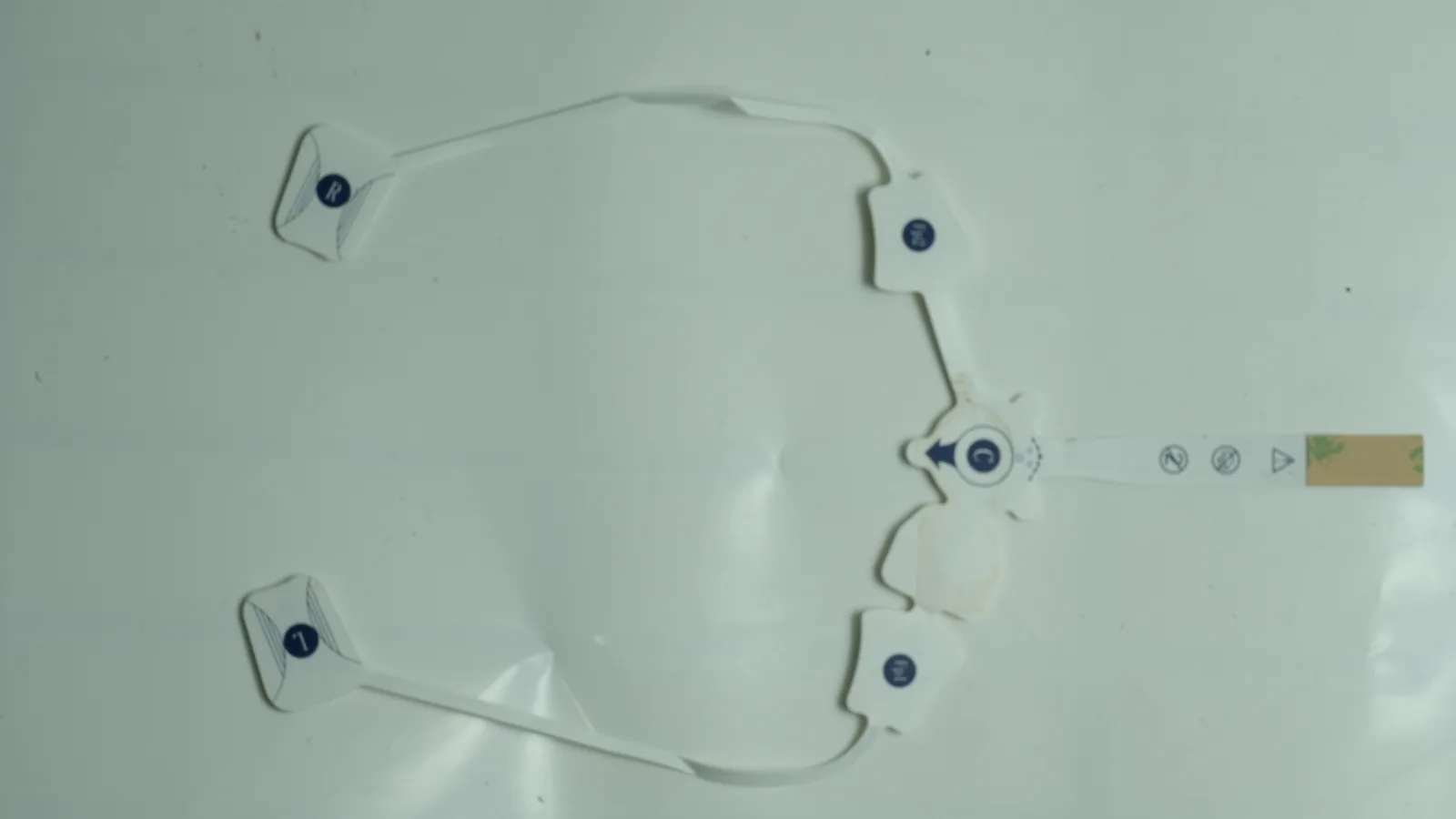
An ECG electrode patch should be specified from the required cardiac lead context, body location, recording duration, motion state, and host electronics. A conventional disposable contact connected by a snap is a different mechanical system from a multi-contact ambulatory patch with a printed tail, even if both expose Ag/AgCl to a hydrogel.
Placement and geometry
ECG placement is not arbitrary artwork. Kligfield and co-authors describe standardized acquisition practices for clinical electrocardiography, while IEC 60601-2-25:2011, IEC 60601-2-27:2011, and IEC 60601-2-47:2012 address diagnostic, monitoring, and ambulatory ECG equipment respectively.^5 Those documents operate at equipment or system scope. They do not certify a printed contact.
For component development, the drawing should define:
- active contact area and exposed-window tolerance;
- patch outline, corner radii, and edge distance from contact to adhesive perimeter;
- center locations relative to a body-placement datum or wearable enclosure;
- snap, lead-wire, or tail position and pull direction;
- conductor route, dielectric overlap, and strain-relief transition;
- gel/adhesive coverage zones and prohibited contamination zones;
- intended flex direction, minimum bend condition, and cable-motion condition.
A larger patch does not automatically improve the signal. More adhesive area may resist edge lift, yet a larger backing can bridge curved anatomy, trap sweat, increase peel force, or transfer cable load to the skin interface. A smaller contact may fit a compact wearable but can become more sensitive to placement, local skin condition, and motion. The customer system must set the acceptance method.
Wear and connection
For a short supervised recording, setup consistency and connector handling may dominate. For an ambulatory patch, sweat, body curvature, repeated flex, edge lift, gel moisture, tail bending, and cable or module inertia become coupled variables. FDA’s 2011 ECG-electrode guidance treats electrical performance, adhesive performance, biological evaluation, and shelf life as separate evidence areas. Passing one electrical coupon does not close the other evidence gaps.
ANSI/AAMI EC12:2000/(R)2020 covers disposable ECG electrodes; FDA lists partial recognition of the 2015 reaffirmation in its consensus-standards database. That scope distinction matters. EC12 is relevant to applicable disposable ECG products, not a blanket standard for EEG arrays, EMG grids, or every reusable dry contact.
When an ECG patch is not the best construction
A pre-gelled adhesive ECG patch is not automatically best for a hair-bearing scalp, a reusable pressure-supported headset, or a high-density muscle grid. It is also not the right default when the host requires a rigid connectorized sensor, a textile-integrated dry contact, or an invasive electrode. The correct route follows intended use, not the familiarity of a round snap electrode.
4. EEG Electrode Array: Position, Reference, Density, and Hair Access
An EEG electrode array starts with a scalp-position framework and acquisition map. The original 10–20 system described by H. H. Jasper in 1958 uses measured cranial landmarks and proportional intervals to improve placement repeatability. Later nomenclature and the 10–5 system add positions for denser measurement layouts.^3 These names define where contacts are identified; they do not mandate one channel count, contact material, cap, adhesive, or clinical claim.
Teams evaluating custom EEG electrode arrays should freeze six linked maps before tooling:
- Scalp-position nomenclature and anatomical datums;
- Physical contact IDs and geometry;
- Reference, ground/bias, and active-channel assignments;
- Flex-tail or harness conductor routing;
- Connector pinout and orientation key;
- Software channel labels and rejected/unpopulated positions.
If any map changes independently, a correctly manufactured array can still feed the wrong scalp location into the wrong software channel.
Geometry is a contact-access problem
EEG must contend with hair, scalp curvature, contact pressure, setup time, and channel-to-channel variability. A flat adhesive contact may suit a hairless forehead location but stand off over dense hair. A spring or pin contact may reach the scalp but creates pressure, comfort, cleaning, and force-distribution requirements. A hydrogel or saline interface can conform locally, yet fluid amount, bridging between nearby contacts, dry-out, and cleanup need limits. Li and co-authors’ 2020 review shows why dry-electrode behavior depends on conformity, pressure, motion, and front-end electronics rather than the label “dry” alone.
Density adds another tradeoff. Reducing pitch can improve spatial sampling for a defined method, but it also crowds dielectric openings and traces, increases connector density, raises the consequence of channel-map errors, and can make gel or saline bridging more likely. A high-density array is not automatically better when the intended protocol needs only a sparse montage, fast setup, or a small wearable footprint.
Interface evidence cannot be borrowed from another headset
Mathewson, Harrison, and Kizuk compared active dry, active wet, and passive wet EEG systems in eight participants. Under that setup, the dry system recovered conventional spectral and P3 findings but had about 44–46% greater single-trial RMS noise than the two wet systems. The result is useful because it shows a system can preserve selected findings while changing noise behavior. It does not rank every dry contact, array geometry, cap force, amplifier, or user population.
The engineering response is a test matrix, not a generic material verdict. Contact usability should be measured by channel and location over setup, motion, and recording time. The protocol should retain the same cap/fixture, front end, reference scheme, filtering, task, and rejection rules when comparing electrode variants.
When an EEG array is not the best construction
A printed multi-contact array is not best when the scalp curvature cannot be accommodated, hair access cannot be controlled, the connector density exceeds the available tail geometry, or cleaning/reuse requirements conflict with the selected adhesives and materials. Separate cap-mounted contacts may be more serviceable. A sparse strip may be more appropriate than a full array when the system observes a limited region and the placement method supports it.
5. EMG Electrodes: Pair Geometry, Fiber Direction, and Spatial Selectivity
Surface EMG electrodes must be specified around a named muscle, anatomical landmarks, local fiber direction, contraction task, and signal-processing method. SENIAM recommendations emphasize documented placement so repeated measurements sample comparable tissue. A catalog description such as “two round electrodes” omits the dimensions that control spatial sampling.
A bipolar surface-EMG pair needs at least:
- active contact diameter or length/width;
- center-to-center spacing and tolerance;
- pair-axis orientation relative to the local muscle-fiber direction;
- array outline and placement datum;
- distance from tendons, muscle borders, or other anatomy as defined by the protocol;
- reference location and electrical role;
- adhesive or fixture behavior during skin and muscle deformation;
- cable/tail exit direction and strain relief.
Why pair geometry changes the sampled signal
Farina, Merletti, and Enoka describe surface EMG as a spatially filtered observation of muscle electrical activity. Electrode active area, pair separation, and orientation influence selectivity and exposure to adjacent sources. Greater separation is not simply “more signal”; it changes the sampled volume and can raise cross-talk exposure. Smaller geometry is not automatically more precise if contact impedance, placement tolerance, motion, or manufacturing registration dominates.
Muscle deformation adds a mechanical failure path that differs from ECG and EEG. During contraction, the skin stretches and the target anatomy moves under the array. A stiff substrate or poorly placed tail can rotate the pair, alter spacing on the body, peel one contact, or inject cable artifact. The sample fixture must reproduce the intended movement rather than test the array only on a flat plate.
Bipolar pair versus high-density grid
A bipolar pair is usually easier to route, connect, place, and inspect. A high-density surface-EMG grid samples a spatial field and supports methods that use many neighboring contacts, but grid pitch, coverage, channel map, reference, connector, acquisition bandwidth, and processing become inseparable system inputs.
A bipolar pair is not the best construction when the project requires spatial activation maps, decomposition methods, regional redundancy, or post-acquisition selection among many contact sites. Conversely, a high-density grid is poor value when the customer needs one documented muscle channel and cannot control placement, connector handling, data volume, or channel-level acceptance.
Custom EMG electrode products should therefore begin with the protocol and channel architecture, not with a preselected patch outline.
6. ECG vs EEG vs EMG Electrodes: Side-by-Side Engineering Comparison
The table below uses the same evidence standard for all three modalities. “Typical” means a common architecture, not a mandatory or universal specification.
| Dimension | ECG | EEG | Surface EMG |
|---|---|---|---|
| Spatial question | Which cardiac vector or wearable-patch field must the system acquire? | Which scalp positions and reference/montage must the system acquire? | Which muscle region and spatial scale must the system acquire? |
| Placement control | Lead configuration or validated patch location | 10–20/10–10/10–5 or controlled proprietary map | Muscle-specific landmarks and fiber-direction protocol |
| Common format | Separate adhesive contacts or integrated multi-contact patch | Cap contacts, strips, sparse or dense arrays | Bipolar pair, linear array, or HD grid |
| Geometry variable | Contact area, patch outline, spacing, edge margin | Contact area, pitch, curvature, hair access | Contact area, pair spacing/grid pitch, orientation |
| Reference architecture | Defined by ECG front end and lead system | Montage/reference/ground defined by EEG system | Bipolar differential, monopolar/grid, and reference defined by system |
| Mechanical challenge | Sweat, peel, body curvature, cable/module motion | Hair, cap force, pressure distribution, bridging, setup | Muscle/skin deformation, pair rotation, cable/tail motion |
| Connector challenge | Snap, lead wire, flex tail, integrated module | High-count harness, tail, pin map, serviceability | Pair lead, flex tail, grid connector, strain relief |
| Applicable evidence example | FDA ECG guidance and ANSI/AAMI EC12 when in scope | Customer EEG protocol and finished-system evidence | SENIAM-informed placement plus customer EMG protocol |
Material selection comes after this table. Ag/AgCl with hydrogel is a common evaluation route for skin-contact recording, but dry metals, conductive polymers, carbon-containing systems, microneedles, textiles, and other interfaces exist in research and commercial systems. No material transfers automatically across anatomy, wear state, cleaning model, or electronics.
Meziane and co-authors compared one gel Ag/AgCl ECG electrode with four dry materials in 24 participants during controlled movements; the reported signal-to-artifact ordering belonged to those constructions and conditions. The study does not select an EEG or EMG interface. The same discipline applies to every supplier test: modality, geometry, fixture, front end, motion, duration, and endpoint must travel with the result.
7. Failure Chains and Validation Boundaries
Electrode failures often begin before the signal reaches software. A dimension moves, an interface dries, a tail loads the contact, or a channel map shifts. The observed symptom may look electrical even when the root cause is mechanical or documentation-related.
| Design input or change | Physical mechanism | Observed system symptom | Control and evidence |
|---|---|---|---|
| ECG adhesive margin too narrow for the cable load | Edge lift changes contact and lets the lead tug the patch | Baseline disturbance or intermittent channel during motion | Peel/shear and cable-motion test on representative anatomy/fixture; inspect lift location |
| EEG contact cannot pass hair consistently | Contact stands off or force varies by site | High or unstable channel impedance; repeated setup attempts | Location-level setup study, force/fit control, channel yield over time |
| EEG pitch reduced without fluid control | Gel or saline bridges adjacent openings | Correlated or shorted channels | Dispense/volume limits, dielectric geometry, bridging inspection and electrical isolation test |
| EMG pair rotates across fiber direction | Spatial sampling changes during placement or movement | Waveform or amplitude changes unrelated to the intended task | Orientation datum, placement fixture/template, motion study, protocol training |
| EMG spacing changes during stretch | Substrate and skin strain alter pair geometry | Task-dependent drift or cross-talk exposure | Strain-mapped drawing, dimensional test under deformation, representative-body fixture |
| Flex tail exits beside an active contact | Tail bending transfers force into the interface | Motion artifact or one-sided lift | Neutral-axis routing, strain relief, cyclic bend plus simultaneous signal check |
| Connector pin map changes after artwork revision | Physical contact ID no longer matches software label | Valid signal assigned to the wrong anatomical location | Controlled netlist/pinout, 100% continuity map, software-hardware configuration review |
| Ink/gel/adhesive changed without stack review | Chemistry or cure alters interface, bond, or conductor | Offset, impedance, adhesion, aging, or residue change | Controlled material revision, compatibility screen, assembled-sample and aging tests |
A useful validation plan separates four evidence levels:
| Level | What it can establish | What it cannot establish |
|---|---|---|
| Printed coupon | Trace resistance, registration, dielectric isolation, adhesion to substrate, bend response under defined conditions | Body-interface behavior, connector durability, signal quality, biological safety |
| Converted electrode component | Geometry, stack dimensions, continuity map, attachment construction, connector pull/bend, packaged component condition | Performance in the customer front end, algorithm output, intended-use safety or efficacy |
| Assembled acquisition system | Channel usability, interface impedance method, offset/noise, motion response, reference scheme, connector and software mapping | Clinical validity, all-user safety, shelf life, or market authorization unless specifically designed and documented for those claims |
| Finished medical device | Intended-use performance, risk controls, biological evaluation, packaging/aging, labeling, usability, regulatory evidence under defined markets | Universal compatibility or performance outside the validated configuration |
For applicable disposable ECG electrodes, FDA guidance and ANSI/AAMI EC12 provide ECG-specific evidence expectations.^6 ISO 10993-1:2025 frames biological evaluation within risk management, while ISO 14971:2019 frames lifecycle risk management.^14 Neither document turns a conductive ink, adhesive, or printed component into an approved finished device.
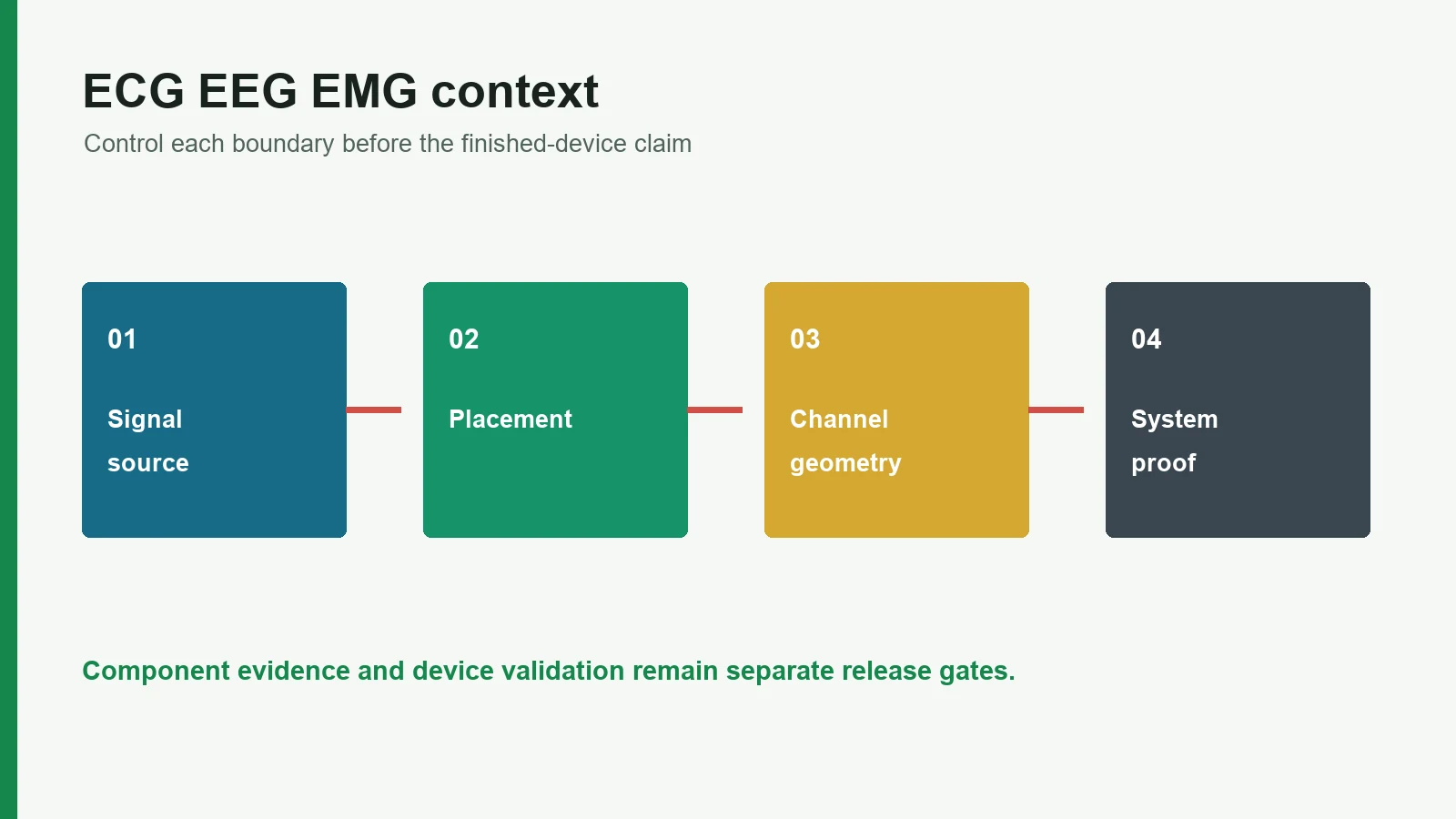
The customer/legal manufacturer must own intended use, applicable standards, host electronics, software and signal processing, risk controls, biological evaluation, packaging and aging, labeling, regulatory pathway, and final release criteria. JASPER or another component producer may build and inspect against an approved specification; that manufacturing evidence remains one part of the device file.
A related wet-versus-dry electrode comparison can help define interface variables. Those variables should then enter the project’s testing and quality controls rather than remain marketing adjectives.
8. Project Input and Sample-Approval Checklist
The fastest route to the correct product family is to submit a signal-context package, not a sketch labeled only “medical electrode.” Start with the medical electrode pads hub, then choose the ECG, EEG, or EMG route after the following inputs are available.
Drawing input checklist
- [ ] Modality and intended use: ECG, EEG, or surface EMG; no mixed shorthand
- [ ] Body site, anatomical landmarks, placement framework, and user/anatomy range
- [ ] Physical electrode IDs, active-area geometry, tolerances, spacing or pitch, and orientation datum
- [ ] Lead/vector, reference, ground/bias, and channel architecture
- [ ] Electrical netlist, connector pinout, mating connector, insertion orientation, and reserved pins
- [ ] Substrate, conductor/contact family, dielectric openings, adhesive or fixture, and skin-interface concept
- [ ] Flex direction, strain zones, tail path, bend limits, connector pull direction, and strain relief
- [ ] Recording duration, motion/contraction task, sweat/humidity, temperature, hair condition, setup method, and reuse/cleaning model
- [ ] Packaging, storage, aging, biological-evaluation, regulatory-market, and change-control requirements
The custom printed medical electrode design guide provides a broader drawing-pack framework. For this comparison, the decisive addition is the placement/channel map that ties each contact to anatomy and software.
Sample approval matrix
The concrete next step is route selection:
- choose the ECG/EKG electrode patch route for cardiac-contact or wearable ECG architectures;
- choose the EEG electrode array route for mapped scalp-contact sets;
- choose the EMG electrode route for muscle-specific pairs or arrays.
9. Frequently Asked Questions
What is the main difference between ECG, EEG, and EMG electrodes?
ECG electrodes sample cardiac electrical vectors from defined body locations, EEG electrodes sample scalp potentials through a placement and reference scheme, and surface EMG electrodes sample electrical activity from a target muscle. Their materials may overlap, but geometry, placement, channel architecture, attachment, and validation do not automatically transfer.
Can the same electrode patch be used for ECG, EEG, and EMG?
Only if the finished system validates that exact construction for each intended use; it should not be assumed. Hair access and cap pressure may govern EEG, muscle orientation and pair spacing govern surface EMG, and lead configuration plus wear mechanics govern ECG. One universal patch is usually the wrong starting specification.
Is an ECG electrode the same as an ECG lead?
No. An ECG electrode is a physical body-contact site. A lead is an electrical view or vector derived from electrode potentials, and a channel is an acquisition path in the electronics. Drawings should keep physical contact IDs, lead definitions, connector pins, and software channel labels separate.
Does an EEG 10–20 layout define the number of electrodes?
No. The 10–20 system defines proportional scalp locations from anatomical landmarks. Expanded 10–10 and 10–5 nomenclatures add positions for denser layouts, while a specific device selects the populated contacts, reference/ground arrangement, channels, connector map, and acquisition protocol.
What controls EEG electrode array pitch and contact size?
The placement nomenclature, required spatial sampling, scalp curvature, hair access, interface medium, bridging risk, contact force, trace/dielectric rules, connector density, and channel-yield target all matter. A smaller pitch or contact is not inherently better; the assembled EEG system must validate the chosen geometry.
What spacing should surface EMG electrodes use?
When should an OEM choose a bipolar EMG pair instead of a high-density grid?
Choose a bipolar pair when one controlled muscle channel, simpler placement, fewer conductors, and a compact connector meet the protocol. Consider a high-density grid when the method needs spatial mapping, decomposition, redundancy, or post-acquisition contact selection—and can support tighter placement, channel mapping, data, and validation demands.
Who validates a custom printed medical electrode?
The component manufacturer verifies agreed drawing and process requirements. The legal manufacturer validates the assembled and finished device: intended-use performance, electronics and software, placement protocol, biological evaluation, packaging/aging, usability, risk controls, labeling, regulatory pathway, and release criteria. Component conformance is not medical-device approval.
Technical References
- Source: FDA Use of ISO 10993-1 Biological Evaluation Guidance. Accessed 2026.
- Source: ISO 10993-1:2025 Biological Evaluation of Medical Devices. Accessed 2026.
- Source: ISO 14971:2019 Medical Device Risk Management. Accessed 2026.
- Source: FDA Design Control Guidance for Medical Device Manufacturers. Accessed 2026.
- Source: Biopotential Electrode Sensors: ECG, EEG and EMG. Accessed 2026.
- Source: Bibliographic search. Accessed 2026.
- Source: DOI 10.1016/S1388-2457(00)00527-7. Accessed 2026.
- Source: PMID 17322457. Accessed 2026.
- Source: ANSI/AAMI EC12:2000/(R)2020, *Disposable ECG electrodes. Accessed 2026.
- Source: Partial recognition record for ANSI/AAMI EC12:2000/(R)2015. Accessed 2026.
- Source: Electrocardiograph Electrodes—Class II Special Controls Guidance for Industry and Food and Drug Administration Staff. Accessed 2026.
- Source: SENIAM project. Accessed 2026.
- Source: DOI 10.1152/japplphysiol.01070.2003. Accessed 2026.
- Source: PMID 25684219. Accessed 2026.
- Source: PMID 28000254. Accessed 2026.
- Source: PMCID PMC7374322. Accessed 2026.
- Source: ISO 10993-1:2025, *Biological evaluation of medical devices—Part 1. Accessed 2026.
- Source: ISO 14971:2019, *Medical devices—Application of risk management to medical devices. Accessed 2026.
- Source: IEC 60601-2-25:2011. Accessed 2026.
- Source: IEC 60601-2-27:2011. Accessed 2026.
- Source: IEC 60601-2-47:2012. Accessed 2026.
- Source: PMCID PMC3716966. Accessed 2026.
Choose the correct biopotential electrode route
Send the current drawing, material stack, electrode roles, connector, use conditions, acceptance methods, program phase, and annual volume.