
EEG electrode array design guide with 10 criteria for scalp geometry, channel maps, printed routing, connectors, wear conditions, and OEM validation.
JASPER certifications: ISO 9001, ISO 13485, IATF 16949, and ISO 14001.
1. Why Array Geometry Is a System Decision
An electrode array is a chain of identities. A scalp location becomes a contact opening; that opening connects to a printed net; the net terminates at a connector pin; the pin reaches an analog-front-end input; software assigns the recorded data a channel label. If one link changes without the others, the component may pass a continuity test while the system records the wrong location.
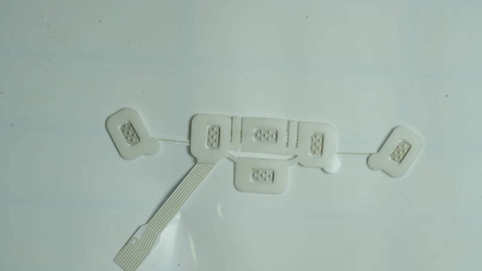
The mechanical problem is equally coupled. A flat carrier must sit on a compound curved, size-variable, sometimes hair-covered surface. Adhesive, hydrogel, edge relief, tail direction, and cable restraint change how contact pressure reaches each site. Debener and colleagues' 2015 cEEGrid study is a useful warning: its C-shaped printed array worked around the ear, yet several participants reported minor discomfort where a grid edge contacted the posterior auricle. That finding belongs to a ten-participant, regional-array study—not every design—but it shows why fit cannot be inferred from artwork alone. (Debener et al., 2015)
Failure chain: how a small release error reaches the data
| Released error | Physical result | Electrical or use result | Evidence that becomes unreliable |
|---|---|---|---|
| Site coordinates lack anatomical landmarks | Array is placed from an approximate edge or centerline | Intended scalp region shifts | Montage comparison and placement repeatability |
| Site label, net name, pin, and software label disagree | Correct contact reaches the wrong acquisition input | Channel identity is swapped | Topographic review and channel-specific acceptance |
| One flat island spans too much compound curvature | Wrinkle, edge lift, or uneven pressure develops | Contact impedance changes with motion | Static bench and short-duration sample results |
| Tail or cable load reaches the contact field | The carrier peels or bends near a trace transition | Intermittent contact or motion artifact appears | Unrestrained wear and movement data |
| Conductive media crosses an insulation boundary | Adjacent contacts couple or bridge | Isolation degrades or a channel shorts | Dry continuity and room-condition inspection |
The design therefore has to close four models together: the anatomical map, the circuit map, the wear stack, and the acquisition interface. Optimizing any one in isolation is how neat drawings become unreliable hardware.
2. The 10-Point EEG Electrode Array Design Framework
The ten criteria are intended use, coordinate system, channel count, reference and ground roles, contact architecture, conformability, printed routing, interconnect mechanics, wear stack, and validation ownership. They are ordered by dependency: later decisions should not be frozen while an earlier one remains ambiguous.
2.1 Freeze intended use and validation ownership first
“EEG” is not a complete requirement. A routine clinical recording, sleep system, regional research patch, ambulatory device, BCI experiment, and consumer headband can need different coverage, contact methods, recording durations, and evidence. The joint IFCN–ILAE guideline conditionally recommends the 25-electrode IFCN montage when feasible for routine and sleep clinical EEG, with the 10–20 array as the fallback. That recommendation does not make 25 positions mandatory for every regional or research device; it establishes a boundary the intended use must resolve. (Peltola et al., 2023)
Teams still choosing the sensing modality should first compare ECG vs EEG vs EMG electrodes, because placement, channel density, wear, and signal-chain assumptions differ. This is an approved planned route and is intentionally linked before launch.
The responsibility matrix should name who owns placement, preparation, front-end electronics, signal acceptance, artifact handling, skin-contact evaluation, cleaning or single-use controls, packaging, software labels, and regulatory submissions. A printed-array drawing cannot settle those subjects by silence.
The input specification names the intended use, operator, scalp region, wear duration, reuse state, environment, host electronics, legal manufacturer, and acceptance owner.
The requirement says only “EEG-ready,” “medical grade,” or “equivalent to a clinical cap.”
2.2 Define positions from anatomy, not a flat-grid pitch
The IFCN coordinate framework locates scalp electrodes from standardized 10% and 20% measurements between anatomical landmarks. That is a surface-coordinate system, not a universal millimeter pitch. The 2017 IFCN proposal recommends a basic clinical array of 25 electrodes, including an inferior temporal chain, and uses 10–10 nomenclature. (Seeck et al., 2017)
For a flexible carrier, release both the clinical or research labels and the manufacturable coordinates. The source geometry should state landmarks, left/right and anterior/posterior orientation, head-size range, nominal surface paths, allowed placement error, and the datum features used by the converted part or placement fixture. If multiple sizes are needed, each size should have its own controlled map instead of scaling the outer profile while keeping contact centers unexamined.
A table links each named site to a 3D or surface coordinate, 2D manufacturing coordinate, contact outline, orientation feature, and revision.
A screenshot of a head map is stretched to fit a die line, or equal spacing on paper is assumed to remain equal on the scalp.
2.3 Separate electrodes, recorded channels, pins, and auxiliary inputs
Electrode count is not automatically the number of recorded EEG channels. The physical array can include recording contacts, a system reference, an isolated ground or bias contact defined by the front end, auxiliary contacts, unused positions, and test features. The connector may also contain shields, keys, duplicate returns, or reserved pins. ACNS Guideline 1 discusses recording channels, electrode positions, reference electrodes, isolated ground, and auxiliary physiological channels as distinct functions. (ACNS Guideline 1, 2016)
Channel-role release table
| Physical role | Required map fields | Interface question | Acceptance owner |
|---|---|---|---|
| Recording site | Scalp label, contact ID, net, pin, AFE input, software label | Does one identity survive from scalp to stored data? | OEM system owner |
| Recording reference | Site, net, pin, AFE reference input, rereferencing plan | Is the acquisition reference compatible with the montage strategy? | EEG/AFE owner |
| Isolated ground or bias | Site, net, pin, equipment-defined function | Does it follow the equipment manufacturer's patient-interface design? | AFE and safety owner |
| Auxiliary contact | Modality, location, net, pin, input type, software label | Is it EEG, EOG, EMG, ECG, impedance test, or reserved? | OEM system owner |
| Manufacturing test feature | Pad/net, access state, removal or coverage rule | Can production test it without creating a patient-accessible ambiguity? | Component manufacturer and OEM |
The controlled channel table is generated from the same revision as the circuit artwork and connector drawing.
The team chooses “32 channels” because a 32-position connector is available, then assigns site, reference, and bias roles later.
2.4 Release reference, isolated ground, and bias roles from the actual front end
Reference and ground are not interchangeable labels. ACNS says an isolated ground should connect to the jackbox as the equipment manufacturer specifies; no electrode should connect to chassis or earth ground. The same guideline advises that the digital recording reference be an additional electrode or combination outside the 10–10/10–20 positions and specifically discourages linked ears as the digital recording reference. Those are clinical digital-EEG recommendations, not a universal reference algorithm for every research device. (ACNS Guideline 1, 2016)
The practical design rule is simpler: the OEM must release the front-end function, pin, site, and post-acquisition rereferencing strategy. If the acquisition IC uses a driven-bias or neutral-electrode function, use its proper name in the schematic and channel table rather than relabeling it “ground” on the mechanical drawing.
The placement map, electrical schematic, connector pinout, and software channel dictionary use the same role names.
A reference and a bias/ground contact share a conductor, or a patient contact is tied to shield, chassis, or protective earth without the equipment safety design.
2.5 Choose the contact architecture for the scalp region and wear protocol
The electrode material alone does not decide contact quality. Hair, skin preparation, conductive medium, pressure, retention, sweat, movement, wear time, removal, and front-end input characteristics interact. The 2023 IFCN–ILAE routine/sleep guideline does not yet recommend dry-electrode systems for that clinical use because movement and sweat artifacts and their mitigation remain insufficiently studied. The same source suggests below 5 kΩ and considers below 10 kΩ acceptable for its clinical recording context, while warning that impedance balance matters. Those values are not printed-trace resistance specifications or universal limits for every amplifier. (Peltola et al., 2023)
| Architecture | Best-fit question | Main design value | Main burden | Usually not the best choice when… |
|---|---|---|---|---|
| Wet printed-film contacts | Can a regional, largely hair-free array use controlled gel or hydrogel zones? | Repeatable relative geometry on one carrier | Hydration, bridging, liner, skin preparation, drying, and package control | The use case requires dry application, reuse, or dense hairy-scalp coverage |
| Semi-dry or micro-reservoir contacts | Can limited conductive medium reach the scalp without flooding adjacent sites? | Controlled local wetting | Reservoir dose, leakage, refill, pressure, wet-state isolation, and cleaning | The fluid path and adjacent-site isolation cannot be verified |
| Dry flexible or three-dimensional contacts | Can mechanical contact remain stable through hair or on hair-free skin? | No gel application step | Contact force, hair access, motion sensitivity, cleaning, reuse, and comfort evidence | Routine clinical use must follow a guideline that does not accept the dry architecture |
| Independent cup electrodes or a conventional cap | Does full-scalp clinical coverage or per-site repositioning matter more than one-piece placement? | Each site can be adjusted separately | Setup time, wiring, gel, operator skill, and cable management | The project needs rapid, repeatable placement of a small regional geometry |
A 2020 forehead-array study used screen-printed Ag/AgCl, a conductive sweat-absorbent sponge, and flexible tines; it also treated sweat-driven cross-interference and shorting between adjacent contacts as design risks. That is a specific forehead prototype, not a universal stack, but it shows why wet-state isolation belongs in the drawing and test plan. (Li et al., 2020)
The planned companion guide on wet versus dry medical electrode tradeoffs carries the wider interface, motion, storage, and validation comparison. Its route is retained as part of the approved content cluster even while the page is not yet live.
The team releases scalp region, hair condition, preparation, contact medium, normal use motion, wear time, removal method, reuse state, and impedance test method.
A contact technology is selected from a single best-looking impedance number without its frequency, amplifier, preparation, environment, or subject conditions.
2.6 Segment the carrier to manage curvature, hair, and edge load
A flexible film bends readily in one direction, but a head presents compound curvature. Forcing one large, unstretched sheet over that surface can create wrinkles, bridged regions, or edge load. Stretchable conductors are one possible architecture; separate islands joined by narrow flex bridges, relief cuts, overlapping subarrays, or a cap that carries smaller printed modules are others. The choice depends on the approved conductor stack, placement method, head-size range, and whether the relative distance between selected contacts must remain fixed.
A PET versus TPU substrate comparison resolves dimensional stability, stretch, cure-window, ink-adhesion, and converting tradeoffs.
Recent on-scalp e-tattoo research used personalized head geometry and path planning before printing electrodes and interconnects. That manufacturing process differs from converting a printed film, but it supplies a useful geometric lesson: a 3D head map should drive the 2D pattern, not the other way around. (Scalco de Vasconcelos et al., 2025)
Locate split lines and relief features where they do not cross contacts, critical traces, adhesive dams, or loaded edges. Mark hairline transitions and obstructions such as the ear or a headset pad. Then inspect site-to-site position after the array is placed, not only while it lies flat.
Fit samples cover the released head-size range and record placed contact coordinates, wrinkles, lifted edges, pressure points, and tail direction.
“Flexible” is treated as proof that one die-cut outline will conform to every head.
2.7 Route printed EEG electrodes from the contact map outward
Routing should begin at the locked contact positions and fan toward a deliberate tail exit. Each net needs a unique name that matches the channel table. The drawing should identify conductor geometry, clearances, exposed contact windows, dielectric boundaries, crossovers or layer changes, guard or shield nets if the electronics owner requires them, flex zones, wet zones, test access, and manufacturing datums.
IPC lists IPC-2223E as the sectional design standard for flexible and rigid-flexible printed boards. It is a relevant framework, not a substitute for the actual ink, substrate, dielectric, cure process, conductor thickness, layer registration, and flex duty. No defensible universal trace width, spacing, or bend radius exists for every printed EEG stack. Those rules must come from the qualified construction and the component manufacturer's process review. (IPC board design standards)
If a single conductive layer cannot escape the contact field without crossings, that is an architecture decision—not a cue to improvise on the production artwork. Options may include rerouting, splitting the array, adding qualified dielectric and jumper operations, or moving to a multilayer/flex-circuit construction. JASPER's custom printed electrode arrays page is a related route for application-specific site maps, routing, dielectric, and connector lands; the quoted construction still defines what is feasible.
The multi-channel printed electrode array design article extends this routing discussion to crossovers, dielectric, tail order, and inspection across non-EEG array applications. The approved route is intentionally linked before release.
Circuit artwork, dielectric artwork, contact-opening artwork, and the net-to-pin table share one revision and one coordinate origin.
The production master is a raster image, or a crossover is added without updating isolation tests and the pin map.
2.8 Keep connector and cable forces out of the sensing field
The tail is both an electrical fan-out and a mechanical load path. Release its exit direction relative to the worn array, conductor order, keep-out zones, intended bends, stiffener, connector contact side, pin 1, keying, insertion depth, retention, mating part, cable direction, and external restraint. A connector that works on a flat bench can torque the nearest electrode island when the user turns their head or when a cable catches on clothing.
Symeonidou and colleagues used a phantom setup to isolate motion-artifact mechanisms and identified cable sway as a major contributor. The result is not a human performance limit, but it supports testing the cable and tail as part of the worn assembly instead of treating them as stationary accessories. (Symeonidou et al., 2018)
Connector pinout also has to preserve patient-interface safety boundaries set by the finished equipment. Touch protection, isolation, defibrillation considerations, and patient-cable requirements belong to the applicable device architecture and standards review. A general FPC connector is not automatically a qualified EEG patient connection.
Connector selection compares snap, tab, lead-wire, and printed-tail handoffs against the device interface and cable load path.
A placed-array drawing shows the cable load path, restraint point, free tail length, mating orientation, and a pull/flex test that represents use.
The connector is chosen by pitch alone, or the stiffener ends beneath a routine bend without a reviewed transition.
2.9 Draw the wear stack as material zones, not a bill of materials
A flexible scalp electrode patch rarely has one material covering the whole outline. The contact may need a wet, semi-dry, or dry interface; traces need insulation; adhesive may surround but not cover an active window; the tail may need no skin adhesive; a handling tab needs a non-tacky region; a stiffener belongs only near the connector. Every boundary requires coordinates and overlap rules.
Map these zones as a controlled medical electrode layer stack, not as an unordered bill of materials. The linked route belongs to the approved electrode-pad content plan even though it is not yet live.
One representative functional stack is shown below. It is not a prescribed JASPER construction, and the physical order can change with the selected architecture.
scalp / hair condition
conductive medium or dry contact geometry project-specific
exposed electrode window
patterned skin adhesive / retention zone
dielectric opening that defines the contact and covers traces
printed conductor and electrode layer
flexible carrier with relief or segmentation features
local backing, handling tab, or edge support if required
release liner until application
contact field · flex transition · tail · stiffener · keyed connector
Release the wear protocol alongside the stack: skin and hair preparation, temperature and humidity, sweat exposure, normal motion, wear duration, single-use or reuse state, removal direction, cleaning, storage, liner removal, and packaging. ISO 10993-1:2025 frames biological safety as a risk-management process tied to materials, design, tissue contact, and exposure duration. A raw-material statement does not establish biological safety for the finished, processed, packaged array. (ISO 10993-1:2025)
The stack drawing names material zones and their boundaries, while the OEM's biological-evaluation plan covers the finished contacting construction and intended exposure.
“Biocompatible adhesive” appears in the BOM with no grade, process state, contact category, duration, or finished-device assessment.
2.10 Split component evidence from finished-device validation
The component manufacturer and OEM can test the same sample for different reasons. Dimensions, registration, continuity, isolation, conductor resistance by an agreed method, contact-window geometry, pin mapping, visual defects, labels, and packaging can confirm that the array matches its released component specification. They do not demonstrate that the system records acceptable EEG in motion, fits the intended population, remains safe on skin, works with an amplifier, or satisfies a market pathway.
IEC 80601-2-26:2019, with Amendment 1:2024 in the current consolidated context, applies to the basic safety and essential performance of electroencephalographs and medical electrical systems. Its scope is a reason to keep passive-array inspection and finished-equipment evidence separate, not a basis for calling an unpowered printed component “IEC compliant.” (IEC 80601-2-26:2019)
Validation ownership matrix
| Evidence block | Example checks | Primary owner | What it does not prove |
|---|---|---|---|
| Printed/converting conformance | Contact dimensions, dielectric openings, site-to-datum position, layer registration, visual criteria | Component manufacturer to agreed drawing | Scalp placement or signal quality |
| Electrical component conformance | Continuity, isolation, net-to-pin map, conductor resistance with named fixture/method | Component manufacturer and OEM | Electrode–skin impedance or AFE performance |
| Fit and wear | Placed coordinates, edge lift, retention, cable motion, sweat/wet bridging, removal | OEM on production-intent assemblies | Biological safety or clinical suitability |
| Signal-chain verification | Interface impedance method, noise, artifact, adjacent-channel transfer, disconnection behavior, AFE compatibility | OEM/device engineering | Diagnostic accuracy or clinical benefit |
| Biological and use evaluation | Patient-contact assessment, preparation, wear duration, removal, cleaning/reuse, usability | Legal manufacturer | IEC equipment compliance by itself |
| Finished-equipment safety and performance | Applicable IEC 80601-2-26 and collateral requirements, patient cable, software, alarms or indicators as applicable | Legal manufacturer/system owner | That every intended clinical claim is validated |
| Clinical/regulatory evidence | Intended-use performance, labeling, human factors, submissions, post-market controls | Legal manufacturer | Transferable approval for another device |
JASPER's testing and validation planning page follows the same separation: drawing-controlled production checks are distinct from project-specific environmental, lifecycle, and assembled-system validation. Exact methods, sample quantities, limits, and records must be agreed for the quoted construction.
The first-article plan assigns every requirement a sample state, method, condition, limit, record, and approval owner.
A continuity pass, material datasheet, or short eyes-open/eyes-closed demonstration is presented as finished-device compliance.
3. Step-by-Step Buyer Process
This six-step process turns the framework into a controlled release. Do not advance a drawing merely because the next prototype slot is available; close the missing dependency first.
Step 1 — Define the recording and regulatory boundary
Write one page that names intended use, users, subject population, scalp region, duration, environment, clinical or research status, contact type, reuse state, host amplifier, software owner, legal manufacturer, and target markets. Add the explicit exclusions. This document decides whether clinical montage guidance, dry-contact research, regional placement, or another architecture governs the project.
Step 2 — Release the placement geometry
Provide the named scalp sites, coordinate system, landmarks, orientation, head-size strategy, contact outlines, hairline assumptions, array split lines, and placement datums. Where 3D data drive the layout, preserve the surface model and the controlled flattening method. Approve fit on representative head forms or subjects under the applicable protocol before freezing the die line.
Step 3 — Close the channel and connector map
For every physical contact, assign a site label, role, circuit net, connector pin, AFE input, and software label. Add reference, isolated ground/bias, auxiliary, shield, reserved, and manufacturing-test positions explicitly. Run an independent map review in both directions: site-to-data and data-to-site.
Step 4 — Release the circuit, stack, and wear drawings
The RFQ package should contain editable geometry plus controlled review copies. The printed medical electrode RFQ files resource will hold the broader intake checklist; its approved 404 route is intentionally retained here. At minimum, close these files:
| Release item | Minimum content |
|---|---|
| Placement master | Sites, coordinates, contact outlines, orientation, landmarks, size, datums |
| Circuit artwork | Nets, routing, widths/clearances by qualified rule, crossovers, flex zones, test access |
| Dielectric and openings | Covered traces, exposed contacts, dams, overlaps, registration tolerances |
| Material-zone stack | Carrier, conductor, contact, adhesive/hydrogel, backing, liner, stiffener, substitutions |
| Tail and connector | Exit, conductor order, pinout, stiffener, keying, mating part, retention, cable restraint |
| Acceptance plan | Flat and placed dimensions, electrical methods, wet/motion checks, sample state, limits, records |
Step 5 — Approve production-intent samples, not presentation models
Use prototyping to answer defined risks. Inspect flat geometry and pin mapping, then place the same construction with its intended liner, retention, connector, and cable. Exercise normal motion, sweat or conductive-medium boundaries where applicable, tail restraint, and disconnection behavior. Record failures by site and net, not only as a pass/fail total. Keep each revision traceable through the electrode patch prototype to production workflow.
Step 6 — Complete OEM validation and freeze change triggers
The OEM validates the array with the released placement method, acquisition electronics, cable, software, wear protocol, biological-evaluation plan, and intended-use evidence. Freeze artwork, material grades, suppliers, cure/conversion processes, connector, liner, package orientation, test methods, and approved samples. Define which geometry, process, material, or packaging changes trigger review or requalification.
4. Release Blockers—and When a Flexible Array Is Not the Best Choice
The following defects should stop an RFQ or sample release until they are resolved:
- No intended-use boundary — “EEG” is the only application description.
- No anatomical coordinate basis — a flat pitch or picture substitutes for landmarks and surface geometry.
- Counts are conflated — electrodes, EEG channels, pins, reference, bias/ground, and auxiliary inputs share one number.
- Reference and ground remain undefined — the placement map is frozen before the AFE interface.
- Raster-only artwork — contacts, traces, dielectric, and die line cannot be dimensioned or revision-compared.
- No placed-fit evidence — a flat flexible part is accepted without the target head-size and hair conditions.
- Static tests only — wet bridging, cable motion, tail restraint, and placed-array behavior are absent.
- Component evidence is overclaimed — continuity or a material sheet is described as IEC compliance, biological safety, or clinical validation.
A one-piece flexible scalp electrode patch is usually not the best choice when routine clinical EEG requires a comprehensive standardized montage that the patch cannot cover; dense hairy-scalp sites need independently adjustable or three-dimensional contacts; anatomy varies more than the carrier can accommodate; the cable cannot be restrained; or reusable, dry, MR, sterile, long-wear, or skin-safety claims lack a dedicated validation program. In those cases, a conventional cap, independent cups, modular regional arrays, or a qualified three-dimensional contact system may be the cleaner architecture.
5. Frequently Asked Questions
What inputs are required before starting an EEG electrode array design?
Start with intended use, scalp coordinate system, named sites, head-size range, hair and preparation conditions, wear duration, contact architecture, channel/reference/ground roles, AFE interface, connector, cable route, material zones, and acceptance ownership. Supply editable geometry and one controlled channel-to-pin table.
Is electrode count the same as EEG channel count?
No. A physical array can include recording contacts, reference, isolated ground or bias, auxiliary contacts, unused sites, and test features. Recorded-channel count and connector-pin count can differ again. <a href=" Guideline 1</a> treats these roles separately.
Where should the reference and ground electrodes go in a multi channel EEG array?
There is no universal location. The OEM must release the acquisition reference, isolated ground or bias function, AFE pin, and rereferencing plan. ACNS clinical guidance says the isolated ground follows the equipment manufacturer's instructions and must not connect to chassis or earth ground.
Are printed EEG electrodes suitable for hairy scalp locations?
Only when the contact geometry, preparation, retention, pressure, motion, and amplifier are validated for the stated hair conditions. A flat contact that works on the forehead should not be assumed to reach hairy scalp. The 2023 IFCN–ILAE routine/sleep guideline does not yet recommend dry systems for that clinical context.
What is the difference between a printed flexible array and a 3D-printed dry EEG electrode?
A printed flexible array usually patterns conductors, contacts, and dielectric on a film or flex substrate. A 3D-printed dry electrode forms a three-dimensional contact body, often to pass through hair. The processes, material stacks, pressure mechanics, cleaning, routing, and validation evidence are not interchangeable.
How should a flexible scalp electrode patch route traces to the connector?
Route outward from locked contact sites to a deliberate tail exit. Control net names, clearances, crossovers, dielectric, wet zones, flex transitions, conductor order, stiffener, keying, pin 1, mating part, and cable restraint. Use the qualified stack's rules rather than a universal trace or bend number.
What should the component manufacturer test on first articles?
Agree on contact and die-cut dimensions, site-to-datum position, layer registration, continuity, isolation, conductor resistance method, net-to-pin map, connector orientation, visual criteria, labels, and packaging. The OEM then adds placed fit, wear, motion, skin-interface, signal-chain, biological, safety, usability, and regulatory validation.
When is a one-piece flexible EEG array not the best choice?
Avoid it when required scalp coverage exceeds the carrier's conformability, hairy sites need individually adjustable contacts, anatomy needs multiple sizes or modules, cable load cannot be isolated, or the intended clinical montage and validation evidence favor a conventional cap, independent cups, or another qualified contact architecture.
6. What to Send Next
Send the channel map and placement geometry before asking a manufacturer to draw the outer profile. Include the site/role/net/pin/software table, head-size and landmark basis, contact and material zones, tail direction, connector and mating part, wear conditions, and the split between component checks and OEM validation. JASPER's EEG array route and relevant component categories, but the quoted project scope and verified evidence control every claim. Files can be submitted through the drawing handoff page.
Technical References
- Source: FDA Use of ISO 10993-1 Biological Evaluation Guidance. Accessed 2026.
- Source: ISO 10993-1:2025 Biological Evaluation of Medical Devices. Accessed 2026.
- Source: ISO 14971:2019 Medical Device Risk Management. Accessed 2026.
- Source: FDA Design Control Guidance for Medical Device Manufacturers. Accessed 2026.
- Source: Debener et al., 2015. Accessed 2026.
- Source: Peltola et al., 2023. Accessed 2026.
- Source: Seeck et al., 2017. Accessed 2026.
- Source: ACNS Guideline 1, 2016. Accessed 2026.
- Source: Li et al., 2020. Accessed 2026.
- Source: Scalco de Vasconcelos et al., 2025. Accessed 2026.
- Source: IPC board design standards. Accessed 2026.
- Source: Symeonidou et al., 2018. Accessed 2026.
- Source: ISO 10993-1:2025. Accessed 2026.
- Source: IEC 80601-2-26:2019. Accessed 2026.
Review the EEG array geometry and channel map
Send the current drawing, material stack, electrode roles, connector, use conditions, acceptance methods, program phase, and annual volume.