
Move an electrode patch prototype to production with seven gates for print trials, sample approval, device validation, pilot controls, and repeat release.
JASPER certifications: ISO 9001, ISO 13485, IATF 16949, and ISO 14001.
A printed patch can look complete while its manufacturing definition is still full of gaps. Electrode geometry may be frozen but the ink remains initial. A circuit may pass continuity on a bench while the connector, skin interface, packaging, or customer electronics remain untested. The practical task is not “make more samples.” It is to assign one question, one evidence set, and one release owner to each build. Name the gate first.
Why a Working Electrode Sample Can Still Fail at Production Transfer
A working prototype proves only what its design, materials, process, conditioning, test method, and sample history allow it to prove. If a hand-cut patch is tested with temporary wiring, for example, that result may answer an early circuit question. It does not establish die-cut registration, production termination strength, liner behavior, packaging, or lot-to-lot control.
The common failure is evidence inflation: a narrow result gets promoted into a broad conclusion. “The trace conducts” becomes “the electrode works.” “The patch worked on one device” becomes “the design is validated.” “The customer liked the sample” becomes “release it for repeat production.” Each jump discards a condition that may matter later.
The failure chain
| Early shortcut | Hidden gap | What appears later | Gate that should stop it |
|---|---|---|---|
| Copy a physical sample without controlled artwork | Electrode area, trace width, datums, and layer boundaries are inferred | Suppliers build different interpretations | Gate 2: drawing feasibility |
| Approve one clean print | Ink identity, cure, thickness proxy, registration, and measurement method are not recorded | Electrical variation appears after process changes | Gate 3: print trial |
| Use hand-cut or hand-laminated samples as the standard | Production tooling and alignment effects are absent | Converted parts shift, expose traces, or misfit mating parts | Gate 4: production-intent conversion |
| Sign “approved” without a matrix | Visual, dimensional, electrical, and assembly decisions collapse into one word | A later dispute has no test condition or owner | Gate 5: sample approval |
| Treat component checks as device evidence | Patient contact, signal chain, use conditions, and system risks remain open | Device validation finds a failure the component inspection never addressed | Gate 6: device validation |
| Repeat a pilot without a released baseline | BOM, deviation, fixture, packaging, or lot identity remains temporary | Repeat orders reproduce an undocumented exception | Gate 7: production release |
The cost is not limited to scrap. An undocumented prototype can force the OEM to repeat device testing because the production article is not demonstrably equivalent. A late material substitution may also affect biological evaluation, signal behavior, adhesive performance, packaging, or a regulatory file. The cure is procedural: preserve the evidence boundary of every sample.
Keep Component Manufacturing Separate from Finished-Device Validation
A printed electrode patch is a component or assembly within a larger system unless the quoted scope and legal status explicitly say otherwise. The manufacturer can verify characteristics of the supplied part. The responsible medical-device organization must determine intended use, risk controls, biological evaluation, electrical safety, clinical evidence, labeling, and market authorization for the finished device.
The U.S. FDA's Design Control Guidance for Medical Device Manufacturers separates design verification, design validation, and design transfer. Verification checks design outputs against design inputs. Validation addresses user needs and intended uses under defined operating conditions, using initial production units or justified equivalents. Design transfer then places approved outputs into controlled production specifications. Those are different decisions, even when a small team discusses them in one meeting.
ISO 14971:2019 provides the lifecycle framework for medical-device risk management. ISO 10993-1:2025 places biological-safety evaluation inside that risk process. FDA's biocompatibility endpoint framework identifies cytotoxicity, sensitization, and irritation/intracutaneous reactivity as endpoints to address for surface devices contacting intact skin, but it does not turn those endpoints into an automatic test checklist for every patch. The device's materials, contact type, duration, processing, prior evidence, and intended use shape the evaluation.
Electrical standards also need scope discipline. ANSI/AAMI EC12:2000/(R)2020 concerns disposable ECG electrodes. IEC 60601-1:2005+A1:2012+A2:2020, Edition 3.2, concerns basic safety and essential performance of medical electrical equipment. Neither title authorizes a generic statement that any loose printed patch is “IEC compliant” or that a component continuity result proves ECG, EEG, EMG, stimulation, or biosensor performance.
| Decision | Component manufacturer can support | Device team retains |
|---|---|---|
| Drawing and BOM | Feasibility review, controlled artwork, material and process questions | Intended function, design inputs, final approval hierarchy |
| Component inspection | Agreed dimensions, registration, appearance, continuity, isolation, circuit mapping, termination, packaging checks | Whether those checks are sufficient for device risks and intended use |
| Material evidence | Supplier identity and documents required by the purchase specification | Biological evaluation, toxicological rationale, patient-contact conclusion |
| Device integration | Mating dimensions, tail/connector, assembly samples, declared conditions | Electronics, signal quality, software, enclosure, use-related and clinical behavior |
| Regulatory work | Supply records within the contracted scope | Submission strategy, labeling, authorization, post-market obligations |
Decision boundary: supplier evidence can enter a device design history or technical file, but it cannot replace the device team's evaluation merely because it is well documented.
The 7-Gate Electrode Patch Prototype-to-Production Path
JASPER can quote prototypes and repeat builds when the project fits the reviewed scope. Screentec, Fraunhofer ZSI, and TE Connectivity also publish prototype-to-pilot or prototype-to-production development routes for printed electrodes or broader medical devices. Their public service pages illustrate that credible pathways differ by materials, equipment, validation scope, and transfer model; the seven gates in this guide are a buyer-side evidence framework, not a claim that one provider owns the only valid process.
The seven gates follow the point at which each decision becomes expensive to reverse. They need not use seven purchase orders. One build may support several gates, provided the sample identity and represented process are clear.
| Gate | Release question | Minimum evidence | Primary decision owner | Do not advance when… |
|---|---|---|---|---|
| 1 | What must the electrode do, and who approves it? | Intended function, contact/use conditions, device interface, applicable requirements, owners | OEM design / systems lead | Function or ownership is still described only by analogy |
| 2 | Can the current definition be manufactured? | Revision-controlled drawing, electrode map, layer stack, materials, termination, datums, tolerances, open-item list | OEM design + supplier engineering | A physical sample substitutes for missing files |
| 3 | Has the printing route answered its feasibility questions? | Trial plan, material identity, artwork revision, process settings, inspection method, results, conclusion | Supplier process engineering + OEM technical reviewer | A good-looking print has no traceable conditions |
| 4 | Does the sample represent the intended converting route? | Production-intent stack, printing, curing, lamination, cutting, termination, liner, packaging, tooling-difference record | Supplier engineering / quality | Hand operations or temporary materials are hidden |
| 5 | Is the supplied electrode sample approved by characteristic? | Sample ID, revision, inspection matrix, deviations, customer comments, signed disposition | OEM engineering / quality / procurement as assigned | “Approved” lacks conditions or open-item status |
| 6 | Does the production-equivalent article work in the customer device? | Integration, intended-use, biological, electrical, mechanical, packaging, and regulatory evidence as applicable | Legal manufacturer / OEM | Component inspection is being used as device validation |
| 7 | Can the process and records reproduce the released article? | Pilot build record, work/inspection instructions, material and lot identity, traceability, packaging, change rules | Supplier operations + quality; OEM release authority | Temporary deviations or unapproved baselines remain |
A gate passes only when its named owner accepts the evidence. Silence is not approval. Shipment is not approval either.
Gate 1 — Define Function, Conditions, and Decision Ownership
Medical electrode prototyping should begin with the signal or energy path, not the patch outline. A recording electrode, stimulation electrode, electrochemical sensor, reference electrode, and patient return electrode present different hazards and acceptance questions. Even within ECG, wear duration, lead arrangement, device input, placement, motion, and packaging can change the evidence plan.
Document at least these inputs:
- electrode function and channel map;
- active area, trace routing, and non-conductive zones;
- body-contact location, contact category, and duration as determined by the device team;
- operating, storage, transport, and application conditions;
- mating electronics, cable, snap, tab, printed tail, or connector;
- single-use, reuse, cleaning, and disposal assumptions;
- applicable device standards, risk controls, and submission needs;
- owner for component acceptance, device validation, and regulatory release.
the OEM supplies a requirement table in which every target has a unit, condition, method or method-development owner, sample stage, and approval owner. Unknowns are marked open rather than filled with supplier guesses.
the input is “same as the reference patch” without controlled geometry, construction, use conditions, or permission to rely on that reference. A commercial sample can guide discussion, but reverse engineering alone does not establish the OEM's requirements or freedom to operate.
Gate 2 — Freeze a Manufacturable Drawing Baseline
Drawing feasibility converts intent into a controlled definition. JASPER's production-intent prototyping framework distinguishes artwork/layout models, functional samples, production-intent samples, and pilot builds because each type closes different questions. That distinction should appear in the RFQ and on the sample record.
Drawing and specification checklist
| Input | What it should control | Open question if missing |
|---|---|---|
| Outline drawing | Overall dimensions, radii, datum scheme, tolerances, cutouts, kiss cuts | Which geometry wins if the physical sample differs? |
| Electrode map | Active areas, count, labels, spacing, orientation | Which area is electrically or chemically functional? |
| Conductive artwork | Traces, pads, crossovers, exposed contacts, keep-outs | Is the visual line a conductor, boundary, or reference? |
| Layer stack | Sequence, material identity, nominal thickness, adhesive/gel coverage, liner | Which layer controls fit, bend, contact, and conversion? |
| Print definition | Ink system, dielectric, cure constraints, coverage, revision | Is material selection fixed, nominated, or proposed? |
| Tail and termination | Exit, exposed contact, stiffener, snap/lead/connector, strain relief | What mates to the customer device, and in which orientation? |
| Inspection plan | Critical characteristics, method, fixture, conditions, limits, records | What evidence releases a sample and later a lot? |
| Device context | Mating enclosure/electronics, application method, use environment | Which interfaces can be checked only in assembly? |
A physical sample remains useful. Measure it, photograph it, and identify what the team intends to preserve. Then issue controlled files. The sample should not carry hidden requirements that cannot be found in the drawing, BOM, specification, or approved-reference record.
each file has a part number, revision, date, precedence rule, and owner. The DFM review returns a disposition for every open item: accept, revise, test, or defer to a named later gate.
suppliers are invited to select different substrates, conductive systems, adhesives, and connectors, then compared on unit price as though their offers describe the same electrode.
Gate 3 — Use Print Trials to Learn, Not to Simulate Production Approval
A print trial should answer a short list of feasibility questions. Can the selected ink/substrate combination form the intended geometry? Does the curing route fit the substrate and other layers? Can registration, dielectric coverage, exposed areas, and the chosen electrical characteristic be measured with a defined method? These are useful answers. They are not yet proof of device performance or repeat manufacturing.
Published work illustrates why the test plan must follow the construction. The 2024 peer-reviewed study Fully Screen-Printed, Gentle-to-Skin Wet ECG Electrodes, the researchers evaluated a specific wet ECG architecture with its own materials, fabrication sequence, and wearable readout. A 2023 peer-reviewed study of screen-printed Ag/AgCl textile electrodes used electrical, mechanical, washing, and ECG evaluations suited to that textile construction. Neither study supplies universal acceptance limits for PET, TPU, hydrogel, dry electrodes, stimulation patches, or a different ink system.
Record the print trial as a small experiment:
- Question: what uncertainty is being tested?
- Inputs: substrate, ink, dielectric, artwork revision, screen or deposition route, and conditioning.
- Process: sequence, cure window, handling, and any departures from the intended production method.
- Evidence: visual criteria, registration, dimensions, resistance/continuity or application-specific measurement, units, instrument/fixture, and sample identity.
- Decision: acceptable for the next experiment, revise, or stop.
the trial report links every result to a sample, artwork revision, material identity, method, condition, and conclusion. Failed trials remain in the learning record instead of disappearing.
a single print passes an unspecified handheld-meter check and becomes the “golden sample.” That sample may be visually useful, but the evidence does not yet define the production route.
Gate 4 — Build a Production-Intent Converted Sample
The printed layer is only one part of the patch. Dielectric coverage, carrier film, contact interface, adhesive, gel, liner, tail, connector, reinforcement, die-cut outline, and packaging can alter fit and function. Gate 4 asks whether the sample represents the materials and operations proposed for production—not merely whether it resembles the final shape.
A practical layer-stack map
Application / handling side
Release liner or placement aid
handling sequence, exposed zones, split, pull direction
Skin-contact or mating interface device team approves use/contact basis
hydrogel, adhesive, dry interface, aperture, or other specified layer
Functional electrode area shared component/device definition
Ag/AgCl, carbon, silver, or another project-defined conductive system
Printed traces and dielectric component manufacturing control
routing, insulation, crossover, contact opening, cure sequence
Carrier / backing / support shared mechanical definition
PET, TPU, textile, or another specified substrate
Tail, snap, lead, tab, or connector device integration interface
orientation, exposed contact, reinforcement, strain relief, mating part
Packaging / labeling / storage surround the stack and require their own release inputs.
Match the sample type to the decision
| Sample type | Useful for | Not sufficient by itself for |
|---|---|---|
| Geometry or artwork model | Outline, electrode location, visual hierarchy, basic fit | Ink behavior, electrical performance, adhesion, production conversion |
| Print-feasibility trial | Pattern formation, selected material/process interaction, early measurement method | Final converting, device use, packaging, process repeatability |
| Functional engineering sample | Circuit map, termination, device connection, selected function under defined conditions | Production equivalence if temporary materials or methods remain |
| Production-intent sample | Proposed materials, print/cure route, lamination, cutting, termination, inspection points | Lot repeatability, sustained process control, future changes |
| Pilot or pre-production build | Work sequence, inspection flow, packaging, traceability, limited-lot repeatability | Unlimited capability or approval of conditions not represented by the pilot |
Any difference between prototype and production intent should be visible in a bridge record. Typical entries include knife cutting versus hard tooling, manual registration versus a production fixture, hand-applied gel versus controlled dispensing, temporary connector versus released termination, or sheet printing versus a later roll process. The record states the difference, why it does not invalidate existing evidence, and what must be rechecked.
the sample traveler identifies every production-intent material and operation, while deviations are marked as deviations with a closure plan.
“same material” is accepted on a trade name alone. Grade, supplier, thickness, surface, lot requirements, processing history, and relevant documentation are not interchangeable details.
Gate 5 — Make Electrode Sample Approval a Matrix, Not a Signature
Electrode sample approval should release named characteristics, not merely a parcel of parts. The approval package links the sample ID to the active drawing, artwork, BOM, material state, process route, test methods, results, deviations, customer comments, and disposition. JASPER's testing and validation planning uses the same principle: identify the characteristic, condition, method, sample stage, limit, record, and acceptance owner before production release.
Electrode sample-approval matrix
| Evidence block | What to inspect or evaluate | Record should identify | Typical owner | Boundary |
|---|---|---|---|---|
| Document identity | Part number, drawing/artwork/BOM revisions, sample stage | Controlling files, precedence, build date, sample IDs | OEM design + supplier engineering | A sample cannot silently override a released file |
| Materials and stack | Substrate, conductive/dielectric systems, adhesive/gel, liner, termination components | Supplier/grade or approved specification, lot where required, layer sequence | OEM materials/design + supplier quality | Material identity is not a biological-safety conclusion |
| Dimensions and registration | Outline, active area, trace/contact position, apertures, layer alignment, tail features | Datum, method, fixture, condition, unit, target/limit, result | Supplier quality; OEM approves critical features | Sampling or full inspection must be stated |
| Print and electrical checks | Opens/shorts, circuit mapping, continuity, isolation, project-defined resistance or impedance checks | Circuit state, contact method, instrument/fixture, frequency/force/conditioning where relevant | Supplier test owner + OEM electrical owner | One method cannot stand in for device signal or energy-delivery validation |
| Converting and assembly | Die cut, kiss cut, exposed zones, liner, gel/adhesive placement, snap/lead/tail, strain relief | Work route, visual criteria, dimensional checks, sample condition | Supplier manufacturing/quality | Hand assembly differences must remain visible |
| Device integration | Fit, connector orientation, placement, electronics interface, signal or stimulation function, motion/use conditions | Device configuration, software/firmware if relevant, operator, protocol, acceptance result | OEM systems/verification/validation | Supplier component approval is not finished-device approval |
| Packaging and traceability | Protection, orientation, labels, pack count, storage/transport inputs, lot link | Packaging revision, label, lot/batch, shipment and report linkage | Supplier operations + OEM quality | Shelf-life or sterile claims require separate evidence |
| Deviations and open items | Temporary material/tool/process, waived characteristic, planned retest | Deviation ID, affected samples/lots, risk rationale, owner, due gate | Named cross-functional approver | An open deviation must not disappear at repeat order |
For an ECG electrode, ANSI/AAMI EC12 and FDA's cutaneous recording-electrode guidance may shape application-specific tests. That does not justify copying ECG limits into a TENS, EEG, EMG, bioimpedance, patient-return, or biosensor specification. Select the standard and method from the intended device function.
What an approval statement should say
A useful approval statement is narrow:
Samples A-01 through A-05, built to drawing revision D, artwork revision C, and BOM revision B, are accepted for the characteristics marked “pass” in this matrix under the recorded test conditions. Deviations DEV-01 and DEV-02 remain open and must close before pilot release. Device-level validation remains the OEM's responsibility.
The identifiers above are formatting examples, not JASPER customer data. They show the fields that prevent an approval email from becoming ambiguous six months later.
visual, dimensional, electrical, assembly, and device decisions can receive different dispositions. Conditional approval has an owner and expiration trigger.
the only record is “sample approved” in an email subject line, with no attached revision, conditions, exceptions, or sample identity.
Gate 6 — Validate the Electrode in the Customer Device
Gate 6 belongs to the responsible device organization. It asks whether a production-equivalent electrode, integrated with the intended hardware and used under defined conditions, satisfies user needs, intended uses, and applicable risk controls. FDA design-control guidance specifically distinguishes this work from verification and calls for initial production units or justified equivalents.
The phrase production-equivalent needs evidence. If the validation unit uses a different ink, adhesive, gel, cure, cutting route, connector, packaging condition, or assembly method, the team should document the difference and explain why it does not compromise the conclusion. When that rationale is weak, rebuild the validation article rather than relabeling the prototype.
The validation plan may need to address:
- placement and application method;
- body-contact category and duration;
- motion, perspiration, temperature, cleaning, or other use conditions;
- mating electronics, cable, connector, shielding, and software settings;
- signal quality, stimulation output, sensing response, or other device function;
- adhesive/contact behavior over the claimed use period;
- packaging, transport, storage, shelf life, and sterilization where applicable;
- usability, labeling, clinical, electrical-safety, and regulatory requirements;
- failure handling and residual risk under ISO 14971:2019.
ISO 10993-1:2025 and FDA biological-evaluation guidance inform a risk-based biological-safety assessment; they do not certify an adhesive or patch by name. IEC 60601-1 Edition 3.2 applies at the medical electrical equipment level, with applicable collateral and particular standards selected for the device. The OEM or legal manufacturer defines and owns these conclusions.
the device validation protocol identifies the production-equivalent rationale, configuration, conditions, acceptance criteria, sample handling, deviations, and report owner.
a supplier continuity report or material declaration is presented as proof of biocompatibility, clinical performance, electrical safety, or market authorization.
Gate 7 — Control Printed Electrode Pilot Production and Repeat Release
Printed electrode pilot production is the first deliberate test of the manufacturing system, not a larger prototype order. It should exercise the proposed materials, tools, work sequence, inspection points, handling, packaging, traceability, and release records at a scale appropriate to the project.
FDA does not prescribe a universal pilot quantity. The number 1,000 must therefore be replaced with the verified JASPER planning rule or removed before release; procurement must not treat it as MOQ.
FDA's Process Validation: General Principles and Practices describes a lifecycle of process design, process qualification, and continued process verification. The guidance is not an electrode-specific rulebook, but its logic is useful: a pilot can contribute evidence, while routine monitoring determines whether the process remains in a state of control.
Pilot-control plan
| Control area | Pilot question | Evidence to retain | Stop / escalation trigger |
|---|---|---|---|
| Released baseline | Did every station use the intended revisions? | Drawing, artwork, BOM, work and inspection instructions | Any conflicting or uncontrolled revision |
| Materials | Were specified materials and relevant lots used and handled correctly? | Material identity, receiving/issue records, storage/conditioning as required | Unapproved substitution or expired/unknown status |
| Printing and curing | Can the defined route produce acceptable patterns under recorded conditions? | Traveler, process settings, in-process results, nonconformances | Drift outside the agreed window or unexplained defects |
| Lamination and converting | Are alignment, coverage, cut, exposed areas, and liner features repeatable? | Tool/fixture IDs, dimensional/visual evidence, defect record | Hidden-feature risk or systematic registration shift |
| Termination and assembly | Does the tail, snap, lead, tab, connector, or reinforcement meet the drawing and device interface? | Assembly record, orientation/fit/electrical checks | Rework dependence or inconsistent mating behavior |
| Inspection system | Do methods, fixtures, samples, units, and limits produce usable release evidence? | Method/fixture IDs, records, inspector/date, lot link | Ambiguous method, poor gauge correlation, missing owner |
| Packaging and logistics | Does the pack protect identity and condition through the defined route? | Packaging revision, label, pack configuration, handling/transport evidence | Damage, migration, contamination, mix-up, lost traceability |
| Nonconformance and change | Can the team contain and disposition deviations without contaminating approved stock? | Segregation, deviation, rework/scrap, concession, affected-lot record | Unauthorized shipment or unclear affected population |
Repeat-order release record
Repeat production should start from an approved configuration that can be reconstructed. JASPER's inspection and traceability framework links the shipped part to active requirements, material identity, process stage, inspection evidence, deviations, labels, packing, lot, and shipment. The record depth remains contractual and project-specific.
| Controlled artifact | Release owner | Reapproval trigger |
|---|---|---|
| Drawing, conductive artwork, layer stack, and BOM | OEM design with supplier document control | Geometry, circuit, material, or interface change |
| Approved production reference and sample matrix | OEM quality/engineering | Reference expiry, damage, revised criteria, process/material change |
| Material and supplier definition | OEM materials/quality + supplier purchasing | Grade, source, composition, thickness, surface, documentation change |
| Tooling, fixture, and process route | Supplier engineering/operations | Tool repair/replacement, equipment, sequence, print/cure or converting change |
| Inspection plan and report format | Supplier quality + OEM quality | Method, fixture, sample plan, limit, or record change |
| Packaging, label, storage, and shipment definition | Supplier operations + OEM quality/logistics | Pack, liner, label, route, storage, shelf-life claim change |
| Deviation and change-control record | Named cross-functional authority | Temporary deviation recurrence or any unapproved carryover |
A repeat order should reference the released part/revision, approved exceptions, quantity, required records, packaging, and any new application or destination requirement. If the order introduces a change, route it through engineering change control rather than relying on the previous approval.
the first repeat order and the pilot can be compared by released documents, material state, process route, inspection evidence, packaging, and trace identifiers.
the only production reference is “build it like last time,” while last time included temporary materials, undocumented rework, or an open deviation.
When This Seven-Gate Path Is Not the Best Choice
A full prototype-to-pilot path adds control, but it is not automatically the fastest or most sensible route.
- Choose a catalog electrode instead when an existing product meets the device interface, evidence, supply, and regulatory needs. Custom development then adds risk without a clear requirement.
- Use a research protocol, not a production release process, when the team is still comparing fundamental sensor chemistries or electrode principles. Freeze only what the experiment needs.
- Do not call a rapid sample production-intent when its substrate, ink, cure, cutting, termination, or assembly differs materially from the intended process and no bridge study can justify equivalence.
- Pause before pilot production when intended use, patient-contact assumptions, test methods, acceptance limits, or device architecture remain unstable. A larger batch will reproduce uncertainty rather than resolve it.
- Do not outsource device responsibility to the component supplier. If the plan expects a component inspection report to close biological, clinical, software, usability, electrical-safety, or regulatory obligations, the responsibility model is wrong.
Eight Release Blockers That Should Stop Release
- No controlled electrode map or layer stack. A sample image cannot define hidden traces, dielectric, adhesive, gel, or liner boundaries.
- Prototype purpose is unnamed. The team cannot tell whether a part is visual, functional, production-intent, or pilot evidence.
- Material identity is vague. “PET,” “TPU,” “silver,” or “medical adhesive” lacks the grade, specification, and approved-source boundary needed for repeat production.
- Electrical criteria omit conditions. A resistance or impedance number without method, frequency, contact, force, conditioning, units, and owner is not reproducible.
- Hand processes are hidden. Temporary cutting, lamination, dispensing, wiring, or rework makes production equivalence unclear.
- Approval has no sample ID or revision. The supplier cannot know which article and document set the customer accepted.
- Component and device validation are merged. Continuity, dimensions, or a supplier declaration is being used to imply clinical or regulatory release.
- Pilot deviations become normal work. Temporary material, rework, fixture, or packaging exceptions carry into repeat orders without authorization.
Project Input Checklist for the First Engineering Review
Send enough information to expose assumptions. Unknown items may remain open if they have owners and closure gates.
-
current 2D drawing with datums, dimensions, tolerances, and revision;
-
electrode/channel map and conductive artwork in a controlled file;
-
proposed layer stack, material specifications, and approved-source rules;
-
intended recording, stimulation, sensing, return, or other function;
-
contact location, duration, environment, application, reuse, cleaning, and disposal assumptions;
-
conductive and dielectric system requirements plus process constraints;
-
adhesive, hydrogel, dry-interface, aperture, coverage, and liner requirements;
-
tail, snap, lead, tab, connector, stiffener, strain-relief, and mating details;
-
customer device, electronics, enclosure, cable, and placement interfaces;
-
critical visual, dimensional, electrical, mechanical, and packaging characteristics;
-
test method, conditions, units, limits, report format, and acceptance owner for each critical characteristic;
-
sample purpose, quantity, pilot intent, forecast context, and required decision date;
-
biological, electrical-safety, clinical, usability, regulatory, and standard responsibilities;
-
traceability, deviation, change-notification, retention, packaging, and shipment requirements.
-
Review a related application path through JASPER's wearable electrode patch page when body-worn integration is relevant.
Frequently Asked Questions
What is the safest path from an electrode patch prototype to production?
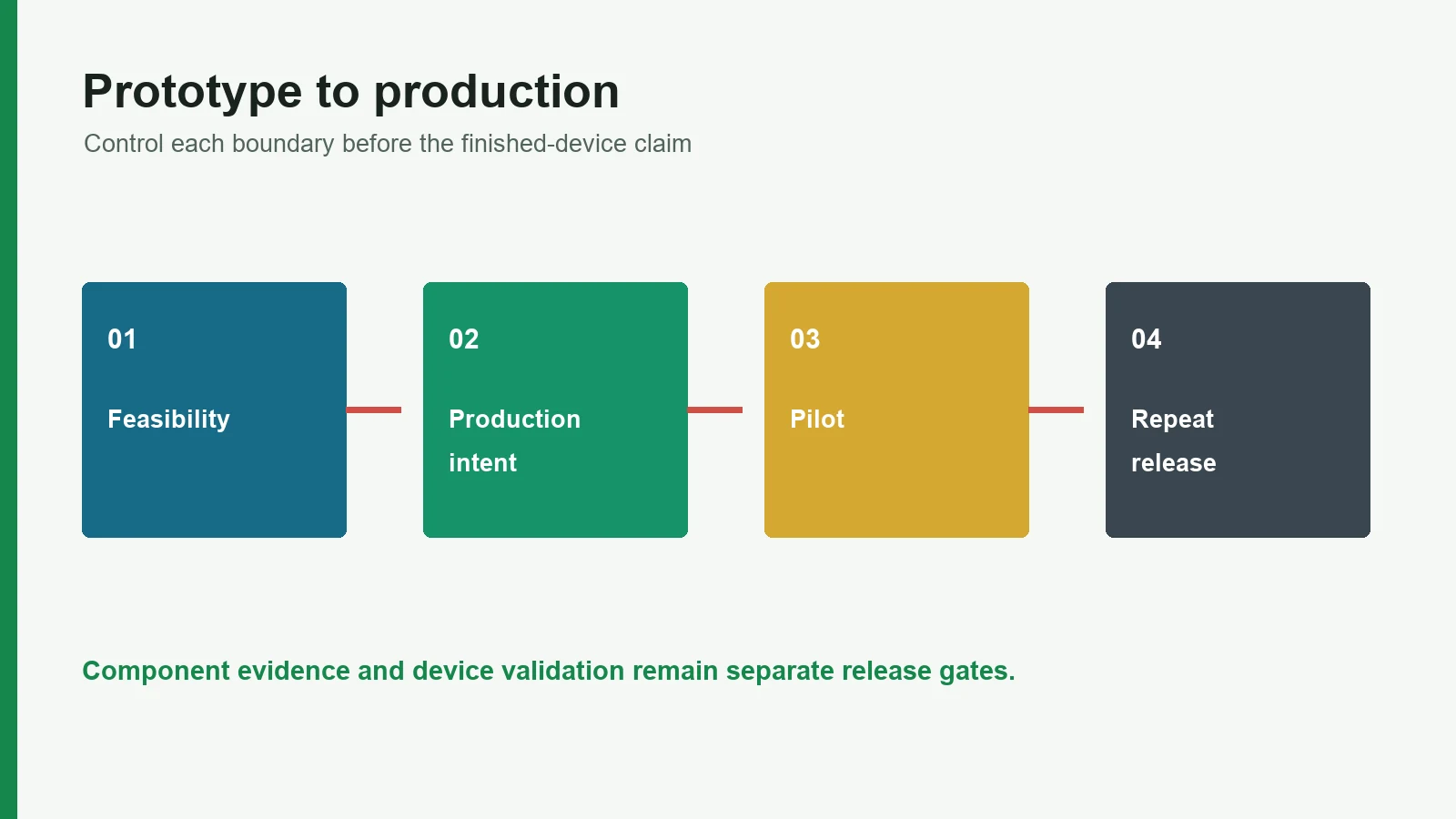
Use seven documented gates: function and ownership, drawing feasibility, print trials, production-intent conversion, electrode sample approval, customer device validation, and pilot/repeat release. Each gate should name its evidence, represented materials and process, decision owner, open deviations, and stop condition.
What is the difference between a feasibility sample and a production-intent sample?
A feasibility sample answers a narrow question and may use temporary materials, tooling, or manual operations. A production-intent sample represents the proposed materials, print/cure route, converting, termination, inspection points, and assembly scope. Any remaining difference should be documented and bridged before validation or pilot release.
What should printed electrode pilot production prove?
A pilot should demonstrate that the released documents, materials, tools, work sequence, inspection methods, packaging, traceability, and deviation controls can reproduce the approved article on an agreed limited lot. It does not prove unlimited process capability or approve future material and process changes.
What belongs in an electrode sample approval record?
Record the sample IDs, drawing/artwork/BOM revisions, material and process state, inspection methods and conditions, results, deviations, customer comments, disposition, and approval owners. Separate visual, dimensional, electrical, assembly, packaging, and device-level decisions instead of using one blanket signature.
Is a continuity test enough to approve a printed electrode?
No. Continuity can detect an open circuit under the stated method, but it does not establish trace resistance under all conditions, electrode impedance, signal quality, stimulation behavior, adhesion, biological safety, connector reliability, packaging, or finished-device performance.
Can ECG electrode limits be reused for every medical electrode patch?
No. ANSI/AAMI EC12 and FDA recording-electrode criteria address disposable ECG electrodes within a defined scope and test method. Stimulation, EEG, EMG, bioimpedance, patient-return, biosensor, and other electrodes require requirements tied to their intended function, device, risks, and applicable standards.
Who owns biocompatibility validation for a skin-contact electrode?
The responsible device organization owns the biological-safety evaluation for the finished device and contact scenario. A component supplier can provide specified material and process evidence, but ISO 10993-1:2025 and FDA guidance require a risk-based evaluation; a material name or supplier declaration is not a universal biocompatibility conclusion.
When does a prototype need to be rebuilt for device validation?
Rebuild or justify equivalence when the validation article differs materially from intended production in ink, substrate, adhesive or gel, cure, conversion, termination, assembly, packaging, or other risk-relevant features. FDA design-control guidance treats “production-equivalent” as a documented rationale, not a label.
What releases a printed electrode for repeat orders?
Release requires an agreed baseline: active drawing, artwork, BOM, approved sample record, material definition, process and tooling route, inspection plan, packaging, traceability, closed or authorized deviations, and change rules. The purchase order should reference that state and identify any new requirement.
Does prototype or sample approval mean the electrode is FDA approved?
No. Prototype approval is an internal engineering or purchasing decision. FDA clearance or approval, CE marking, and other market authorizations apply through the relevant finished-device pathway and responsible legal manufacturer. A component sample approval does not create regulatory authorization.
Source References
- U.S. FDA — Design Control Guidance for Medical Device Manufacturers
- U.S. FDA, January 2011 — Process Validation: General Principles and Practices
- U.S. FDA — Biocompatibility Evaluation Endpoints by Device Category
- U.S. FDA — Cutaneous Electrodes for Recording Purposes: Performance Criteria
- ISO — ISO 14971:2019, Medical devices—application of risk management
- ISO — ISO 10993-1:2025, biological evaluation within risk management
- IEC — IEC 60601-1:2005+A1:2012+A2:2020, Edition 3.2
- AAMI — ANSI/AAMI EC12:2000/(R)2020, Disposable ECG electrodes
- npj Flexible Electronics, 2024 — Fully Screen-Printed, Gentle-to-Skin Wet ECG Electrodes
- Sensors, 2023 — Washable and Flexible Screen-Printed Ag/AgCl Textile Electrodes for ECG Monitoring
- DeviceLab — Medical Device Prototyping and Pilot Production
- Dinghmed, April 2024 — The Medical Device Manufacturing Process in 6 Steps
- Screentec, July 2026 — ECG Electrode Manufacturing Process: From Design to Finished Product
- Fraunhofer ZSI — Prototyping to Pilot Production
- TE Connectivity — Medical Pilot Manufacturing
Plan the Prototype and Pilot Acceptance Gates
Before requesting more samples, build a one-page gate plan: list the current revision, sample purpose, represented materials and processes, evidence required, decision owner, unresolved items, and the next release condition. Then send the controlled drawing package through JASPER's drawing-review route for a feasibility discussion tied to the quoted component scope.
Technical References
- Source: FDA Use of ISO 10993-1 Biological Evaluation Guidance. Accessed 2026.
- Source: ISO 10993-1:2025 Biological Evaluation of Medical Devices. Accessed 2026.
- Source: ISO 14971:2019 Medical Device Risk Management. Accessed 2026.
- Source: FDA Design Control Guidance for Medical Device Manufacturers. Accessed 2026.
- Source: Design Control Guidance for Medical Device Manufacturers. Accessed 2026.
- Source: biocompatibility endpoint framework. Accessed 2026.
- Source: Fully Screen-Printed, Gentle-to-Skin Wet ECG Electrodes. Accessed 2026.
- Source: screen-printed Ag/AgCl textile electrodes. Accessed 2026.
- Source: cutaneous recording-electrode guidance. Accessed 2026.
- Source: Process Validation: General Principles and Practices. Accessed 2026.
- Source: Biocompatibility Evaluation Endpoints by Device Category. Accessed 2026.
- Source: Cutaneous Electrodes for Recording Purposes: Performance Criteria. Accessed 2026.
- Source: ISO 14971:2019, Medical devices—application of risk management. Accessed 2026.
- Source: ISO 10993-1:2025, biological evaluation within risk management. Accessed 2026.
- Source: IEC 60601-1:2005+A1:2012+A2:2020, Edition 3.2. Accessed 2026.
- Source: ANSI/AAMI EC12:2000/(R)2020, Disposable ECG electrodes. Accessed 2026.
- Source: Washable and Flexible Screen-Printed Ag/AgCl Textile Electrodes for ECG Monitoring. Accessed 2026.
- Source: Medical Device Prototyping and Pilot Production. Accessed 2026.
- Source: The Medical Device Manufacturing Process in 6 Steps. Accessed 2026.
- Source: ECG Electrode Manufacturing Process: From Design to Finished Product. Accessed 2026.
- Source: Prototyping to Pilot Production. Accessed 2026.
- Source: Medical Pilot Manufacturing. Accessed 2026.
Plan prototype, pilot, and repeat-release gates
Send the current drawing, material stack, electrode roles, connector, use conditions, acceptance methods, program phase, and annual volume.