
Use this 10-part medical electrode RFQ requirements checklist to prepare drawings, layer artwork, materials, interfaces, tests, packaging, and approvals.
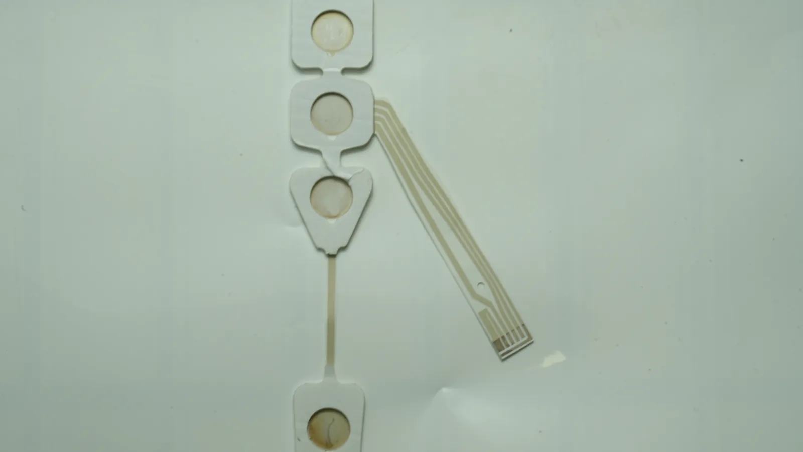
JASPER certifications: ISO 9001, ISO 13485, IATF 16949, and ISO 14001.
Why a Medical Electrode Quote Changes When the Files Change
A medical electrode quotation is an answer to a specific revision, not a price attached to a product name. “Ag/AgCl patch,” “wearable electrode,” or “printed sensor” leaves open the active geometry, trace path, dielectric coverage, substrate, contact layer, termination, package state, inspection method and the point where the component enters the customer's device.
Those gaps matter because several visually similar constructions can require different print passes, conversion steps, purchased materials, fixtures and evidence. A supplier that fills the gaps silently may price a different product from the one the OEM intends to validate. A supplier that lists every gap may issue a initial quote, but the buyer still cannot compare it with a quote based on a released stack.
The U.S. Food and Drug Administration's ECG-electrode guidance illustrates the needed technical discipline. Within its ECG scope, FDA recommends defining materials, construction, type, dimensions and supply state, then evaluating biological, electrical, adhesive and shelf-life characteristics. The same guidance distinguishes electrodes, conductive media, lead wires and patient cables rather than treating them as one generic part. It is a useful specification model, although its complete test set must not be applied automatically to EEG, EMG, stimulation or electrochemical-sensor designs. See the FDA ECG electrode guidance.
For teams sourcing printed medical electrode pads, the practical rule is simple: quote uncertainty should appear as a written assumption, not disappear into the supplier's estimate. A missing decision can remain open, but it should be marked not yet defined — owner + decision date.
Medical Electrode RFQ Requirements at Three Maturity Levels
Medical electrode RFQ requirements change with the decision being requested. A rough sketch can support feasibility review. It cannot support the same commercial comparison or production control as released artwork, a BOM and approved test limits.
| RFQ maturity | Minimum useful input | Legitimate output | What it is not |
|---|---|---|---|
| Concept review | Intended function; approximate electrode map; body, sample or equipment interface; rough outline; connection concept; known materials; open questions; initial quantity context | Feasibility questions, candidate manufacturing routes, missing-data list and a clearly initial commercial range if the supplier chooses to provide one | A production quote, approved design or claim that the material stack is suitable for patient contact |
| Comparable quotation | One drawing revision; editable geometry plus review PDF; defined layer roles; candidate or locked BOM; contact and connector interfaces; conversion scope; packaging state; prototype and forecast quantities; acceptance outline | A quote tied to the same baseline, with tooling, material, process, test, packaging and exclusion assumptions separated | Permission to manufacture an uncontrolled revision or evidence that the finished device is validated |
| Production release | Approved master drawing and layer artwork; released BOM and sources; process and inspection requirements; approved sample status; packaging/label files; records; deviation and change rules | A controlled manufacturing baseline and purchase specification for the scope accepted by both parties | Transfer of intended-use, clinical, biological, risk-management or regulatory ownership by default |
This maturity label belongs on the cover sheet. Without it, purchasing may read a feasibility estimate as a firm production offer, while engineering assumes the supplier has approved details that were never supplied.
The 10-Part Printed Electrode Drawing Checklist
A printed electrode drawing checklist should connect every physical feature to a controlled artifact and a decision owner. The matrix below is the short version; the subsections explain what a usable file contains and what omission usually hides.
1. Start with an RFQ Cover Sheet and Responsibility Map
The cover sheet tells a reviewer what decision the package is meant to support. It should identify the project, confidentiality status, RFQ maturity, current revision, target application category, manufacturing handoff and contacts for design, quality and sourcing. It should also list every unresolved item with an owner and expected decision point.
The responsibility map is more important than a vague “medical use” statement. Define who selects patient-contact materials, who supplies label text, who validates electrical or electrochemical behavior, who owns biological evaluation, and who releases the finished device. FDA's current Quality Management System Regulation applies to finished-device manufacturers within its scope and became effective on February 2, 2026. A component RFQ should not imply that those obligations move simply because a supplier prints or converts the electrode.
A one-page manifest states Comparable quotation, names the OEM as finished-device owner, and marks the gel decision not yet defined — biological safety lead — gate before prototype build.
The package says “supplier responsible for FDA compliance” without identifying the finished device, legal manufacturer, market, deliverables or acceptance evidence.
2. Release a Dimensioned Master Drawing, Not Only a Screenshot
The master drawing controls the physical envelope. Include units, scale status, datum scheme, outer profile, holes and openings, electrode-center locations, active outlines, critical spacing, tail exit, mating features, bend or keep-out zones and tolerances. Use section views where the stack or connector cannot be understood in plan view.
Send both a readable PDF and the editable geometry needed for the quoted process. JASPER's route to send the current drawing package lists PDF for review, DXF or DWG for outline geometry, AI or CDR for vector artwork, and STEP when the housing affects fit. Those are accepted examples, not a rule that every project needs every format. A supplier should state which file becomes the manufacturing master.
The PDF and editable drawing carry the same project number and revision, and critical dimensions are toleranced from stable datums rather than derived from a scaled image.
A raster image is labeled “1:1,” but there are no units, datums, native vectors or revision identifier.
3. Separate Electrode, Trace, Dielectric and Connector Artwork
Printed artwork must show functional identity, not just color. Separate the active electrode regions, routed conductors, dielectric or passivation windows, connector lands, reference features, registration marks and any additional print layers. Add a legend that maps every electrode or channel name to its role and pin assignment.
For a biosensor, working, counter and reference regions need explicit names. For a multi-site biopotential patch, channel identity and anatomical placement references may drive the map. The supplier needs printable geometry; the device team still validates function, cross-talk, signal interpretation and placement.
Each layer is supplied as an editable vector plus a locked review PDF, and a composite overlay proves which conductor areas remain exposed after dielectric printing.
One flattened image contains several colors, but no document says whether a color means conductor, Ag/AgCl, dielectric, cut line or annotation.
4. Define the Material Stack and BOM by Grade and Function
A medical electrode specification must identify the complete stack. For each layer, record function, material manufacturer and grade when fixed, thickness or coat requirement, surface treatment, applicable supplier document, orientation, process limit, storage condition and whether substitution is prohibited or requires approval. If two candidates remain under evaluation, list them as separate build variants rather than joining them with “or equivalent.”
Chemistry names are not specifications. Ag/AgCl formulations can differ in silver-to-silver-chloride ratio and process behavior; PET films differ in surface and thermal history; hydrogels and PSAs differ in thickness, tack, electrical behavior, liner and storage needs. Material data can guide design, but biocompatibility assessment considers the whole device in final finished form, including manufacturing, residuals, packaging and sterilization where applicable. FDA does not approve a raw material in isolation. See FDA's biocompatibility assessment basics.
The BOM ties each layer to a controlled source document and says, “No material substitution without OEM review of process, biological and device-level impact.”
The stack says only “medical-grade adhesive, PET and Ag/AgCl,” with no grade, thickness, exposed zone, cure limit or change rule.
5. Specify the Hydrogel, Adhesive, Membrane and Liner Interface
The contact-interface file should show exactly where each material sits. Dimension the hydrogel or adhesive coverage, exposed electrode area, overlap, adhesive-free zones, edge clearance, spacer or membrane openings, liner split, pull tabs and placement sequence. State intended contact site, contact nature and duration, wear or measurement condition, removal condition, storage environment and conditioning before any test.
ISO 10993-1:2025 places biological-safety evaluation within risk management and considers the nature and duration of body contact. It does not turn a supplier data sheet into finished-device evidence. For applicable PSA comparisons, ASTM D3330/D3330M is one possible peel-adhesion method, but a standard-panel peel result is not a skin-wear claim. The actual substrate, conditioning, angle, rate, dwell, sample preparation and acceptance limit must be written into the method.
A zone drawing and interface specification name the exact gel/PSA/liner, conditioning, test substrate, coverage and OEM owner for biological and wear validation.
A supplier is asked to “choose skin-safe adhesive” without intended contact duration, population, removal condition, device risk analysis or approval owner.
6. Draw the Tail, Snap, Lead or Connector as a Mating System
An interconnect is not complete when the drawing ends at a contact pad. Specify contact count and pitch, pinout, tail length and exit, stiffener geometry, exposed-contact finish, snap or lead attachment, mating part number, insertion envelope, retention, bend direction, minimum keep-out zone, strain transition and the assembly step that connects it to the host electronics.
Add the mating connector drawing or a controlled interface-control document. If the customer supplies a lead, snap or PCB, say who procures it, who inspects it and at which point it enters the build. If electrical continuity or resistance is checked, mark the exact test points and fixture contacts so the result can be reproduced.
The tail drawing references the mating connector revision, identifies contact 1, controls stiffener and insertion geometry, and shows where bending may begin.
The RFQ says “standard snap” or “ZIF tail” but supplies no mating part, pitch, pinout, retention or mechanical envelope.
7. Control Die Cutting, Lamination and the Supplied Assembly Level
The conversion drawing defines what the supplier delivers after printing. Show outer die lines, holes, slots, kiss cuts, islands, laminate overlaps, protected regions, registration datums, handling tabs, liner splits, edge exposure and the sequence in which layers are assembled. State whether the deliverable is a printed circuit, a converted subassembly, a finished patch without device release, or another clearly bounded level.
Registration tolerances should link the cut profile to active electrode sites, dielectric windows, adhesive zones and connector features. The RFQ may reference precision die cutting and lamination and assembly as review areas, but the released drawing still controls the actual project.
A composite inspection view identifies the datum, print-to-cut and layer-to-layer characteristics that quality will measure.
Separate vendors receive separate drawings, but no controlled assembly view establishes how their tolerances accumulate.
8. Treat Packaging, Labels and Supply State as Design Inputs
Packaging begins with the condition in which the electrode must reach the next operation or end user. Define unit count, orientation, contact-surface protection, liner state, pouch or tray, clean handling, desiccant or other controls if justified, seal and package checks, storage range, lot identification, variable data, label artwork owner and supplied state such as sterile or non-sterile.
ISO 20417:2026 covers information supplied by the medical-device manufacturer, including identification, labels, packaging information and accompanying documentation. ISO 15223-1:2021 provides medical-device symbols, where applicable. Neither standard authorizes a component converter to invent claims or label content. If the final product is terminally sterilized, ISO 11607-1:2019 may become relevant to the sterile-barrier system; it is not a universal packaging requirement for every printed electrode component.
Separate controlled files cover package construction, label content, variable fields and the approver; the RFQ states whether JASPER or another party prints, applies or only protects the label.
The drawing says “medical pouch” or “sterile pack” without a sterilization owner, barrier specification, process boundary, label release or validation plan.
9. Write the Inspection, Test and Sample-Approval Plan Before Quoting It
Every acceptance characteristic needs a method, fixture, conditioning state, measurement location, unit, limit, sampling rule, record and approver. Typical manufacturing evidence may include artwork/revision verification, dimensions, registration, visual criteria, continuity, project-defined resistance, isolation, connector attachment, lamination, die-cut alignment, label and package state. None of those checks automatically proves device performance.
For disposable diagnostic ECG electrodes, FDA's guidance points to ANSI/AAMI EC12 or equivalent methods for AC impedance, DC offset voltage, combined offset instability/internal noise, defibrillation overload recovery and bias-current tolerance. That list is ECG-specific. The FDA-recognized edition and exclusions must be checked for the intended submission, and the RFQ must not copy numerical limits into unrelated electrode types.
The plan links characteristic EL-03 to drawing points, fixture revision, conditioning, method, limit, sample rule, raw-data record and OEM approval.
The purchase order says only “100% electrical test” or “must pass ISO 10993,” without a product scope, method, endpoint, limit or evidence owner.
10. Add Quantity, Milestone, Records and Change-Control Inputs
Then define change behavior. Which artwork, material source, process, tooling, fixture, test, label or package changes require notification? Who may approve a deviation? Which changes require new samples or OEM requalification? The answers should connect the quote to inspection and traceability and engineering change control, not rely on email history.
The RFQ separates prototype and forecast quantities, identifies required records and lists requalification triggers before purchase terms are compared.
The quote is requested for “production volume” with no variant count, forecast basis, program stage, supplied material, record requirement or change rule.
Read the Stack as a Responsibility Map, Not a Standard Construction
The diagram below is a scope map. It shows questions that often cross a printed-electrode supply chain; it does not recommend one universal stack or layer order.
Finished-device information and package
label / variable data / IFU owner
pouch, tray or sterile-barrier boundary when applicable
storage, transport and shelf-life evidence owner
Converted contact assembly
release liner and placement sequence
hydrogel, PSA, spacer or membrane zones
backing, reinforcement or nonwoven layer
die cuts, apertures, tabs and registered laminate edges
Printed electrode circuit
exposed electrode areas: Ag/AgCl, carbon or specified system
conductor traces and dielectric / passivation windows
flexible substrate and process limits
tail, snap, lead or connector interface
Customer system
electronics, placement, signal or stimulation function,
risk controls, clinical use and regulatory release
A printed flexible stack is not the best choice by default. Reconsider the architecture when the intended device needs dry electrodes, implantable materials, defibrillation or other high-energy therapeutic transfer, dense active electronics better served by FPC/PCB, repeated dynamic flex outside the verified construction, or a separately validated sterile-barrier process. The device risk analysis and interface requirements should select the architecture; the RFQ should document that decision rather than force every program into printed PET, Ag/AgCl and hydrogel.
Package the Files So the Revision Is Unambiguous
A useful RFQ contains editable source data, locked review copies and a manifest. The exact file extensions can change by supplier, but the revision relationship cannot.
| Information set | Human-readable review copy | Editable or machine-usable source | Control note |
|---|---|---|---|
| Mechanical outline and datums | Dimensioned PDF | DXF, DWG or applicable 3D interface file | The supplier must name the manufacturing master |
| Print and dielectric layers | Composite PDF with legend | AI, CDR, Gerber or another agreed vector/layer format | Keep conductor, electrode, window and annotation roles separate |
| Stack and BOM | Approved PDF | XLSX, CSV or controlled product-lifecycle record | Identify source documents, status and substitution rules |
| Tail and mating interface | Interface-control PDF | CAD data required by the chosen connector/assembly process | Include mating revision and pin identity |
| Test and sample approval | Signed review PDF | Structured worksheet or quality-system record | Link every result to method, fixture, limit and sample revision |
| Packaging and label content | Package drawing and label proof PDF | Agreed artwork and variable-data source | The device owner approves claims and released content |
PROJECT-ELECTRODE_RFQ_RevB/
00_manifest/
PROJECT_RFQ_manifest_RevB.pdf
responsibility_matrix_RevB.pdf
01_master_drawing/
electrode_master_RevB.pdf
electrode_outline_RevB.dxf
02_print_artwork/
electrode_and_trace_RevB.ai
dielectric_windows_RevB.ai
composite_review_RevB.pdf
03_stack_and_materials/
stack_BOM_RevB.xlsx
approved_supplier_documents/
04_interfaces_and_conversion/
contact_interface_RevB.pdf
tail_connector_ICD_RevB.pdf
cut_laminate_assembly_RevB.pdf
05_test_and_approval/
acceptance_matrix_RevB.xlsx
sample_approval_form_RevB.pdf
06_packaging_and_labels/
packaging_spec_RevB.pdf
label_artwork_RevB.pdf
The manifest should list each file, revision, date, status and precedence rule. It should also identify superseded files. A ZIP filename that says FINAL_v7_new is not revision control; it is archaeology with compression.
Run the Medical Electrode RFQ in Six Controlled Steps
The buyer process should move one baseline from question to quote to approved sample. Each step closes a different kind of uncertainty.
Step 1 — Name the Decision and the Manufacturing Boundary
Choose Concept review, Comparable quotation or Production release. Then write one sentence defining the supplier's handoff: printed circuit only, converted subassembly, packaged patch or another controlled scope. Assign intended use, patient/sample contact, electronics, clinical claims and regulatory release to named owners.
Step 2 — Build the Manifest Before Sending the ZIP
List every file, revision and status. Pair editable artwork with locked review copies, identify the controlling file and mark open decisions. Run the 10-part checklist once. If the package cannot answer a criterion, add an owner and decision date instead of hiding the gap.
Step 3 — Issue One Baseline to Every Bidder
Send the same package, quantities and requested evidence to every candidate. Early packages can go through JASPER's route to send the current drawing package; that page records project context but does not upload attachments. Use the supplier's stated secure transfer method for controlled files.
Step 4 — Convert Questions into Quote Assumptions
Step 5 — Approve the Sample Against the Matrix
Release one sample revision and record every approved deviation. Evaluate geometry, registration, materials, interconnect, handling, package state and agreed manufacturing tests. Route device-level evidence to the correct owner. A related printed medical electrode array project can provide application context, but its construction or outcome must not be copied into a new program without evidence.
Step 6 — Freeze the Production Baseline and Change Triggers
Link the approved sample to the drawing, artwork, BOM, process route, fixtures, inspection plan, packaging and records. State which changes need notification, new samples or OEM requalification. Production may begin only against the released scope accepted through the project's purchasing and quality controls.
Build a Sample Approval and Validation Matrix Before Ordering
A sample approval matrix prevents manufacturing evidence from being mistaken for finished-device validation. ISO 14971:2019 provides a life-cycle risk-management framework, but it does not set a universal electrode risk limit. The device team should use its risk controls to decide which outputs flow down to the component specification and which evidence remains at system level.
| Approval block | Example evidence in the RFQ | Normal evidence owner | Boundary |
|---|---|---|---|
| Revision and identity | Manifest, artwork hash or controlled revision, BOM and deviation log | OEM and supplier document control | Proves which definition was reviewed, not that it is clinically suitable |
| Geometry and registration | Datum-based dimensions, active-site position, print-to-cut and layer alignment | Supplier inspection; OEM approval | Uses project limits; no generic tolerance is assumed |
| Material and process identity | Material lots, approved sources, print/cure route and substitution status | Supplier records; OEM material approval | Traceability does not establish biological safety |
| Electrical manufacturing checks | Continuity, resistance or coupon result using named points, fixture and limits | Supplier when quoted; OEM approves method | Does not replace ECG, EEG/EMG, stimulation or assay-system performance testing |
| Contact and adhesive interface | Coverage, liner, peel or tack method, conditioning and removal observations | Shared manufacturing evidence; OEM device validation | Standard-panel peel data is not a wear-duration or skin-safety claim |
| Interconnect and assembly | Pinout, insertion, retention, strain transition and mating fit | Supplier and OEM integration team | Must be checked with the real mating system |
| Packaging and labels | Correct count, orientation, protection, label revision, seal/package check and storage marking | Supplier for quoted operations; device owner approves content | Sterile barrier, shelf life and transport claims require their own validation |
| Finished-device release | Biological evaluation, intended-use performance, risk controls, clinical evidence and market submission | Legal/finished-device manufacturer under the actual arrangement | Outside a component quote unless explicitly contracted and supported |
The approved sample is therefore a manufacturing reference, not a universal “golden sample” that overrides the drawing. If the sample and released documents conflict, the package must say which one controls and resolve the mismatch before repeat production.
Eight Release Blockers That Should Stop the Quote
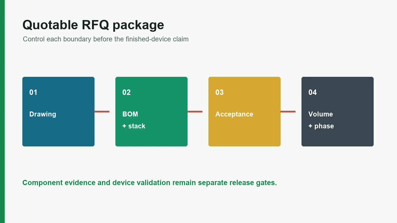
These release blockers override a polished presentation or a low price:
Frequently Asked Questions
What are the minimum medical electrode RFQ requirements for an early quote?
An early quote needs the intended function, approximate electrode map, outline, layer concept, contact interface, connection method, supplied assembly level, prototype and forecast quantities, required evidence, and a list of open decisions with owners. The result should be labeled initial until geometry, materials and acceptance criteria are controlled.
Is a PDF enough for a printed electrode quote?
A dimensioned PDF can support review and sometimes a initial quote, but it is rarely sufficient as the production master. The supplier may also need editable CAD or vector artwork for outlines, print layers and cut data. The RFQ manifest should identify which file controls and how revisions match.
Which CAD and artwork files should be sent for a printed electrode?
Send a readable PDF plus the editable formats the selected process requires. JASPER publicly lists DXF/DWG for outlines, AI/CDR for vector artwork, STEP for housing context, and Gerber among possible circuit files. These are options, not a requirement to send every format; confirm the manufacturing master with the supplier.
Must ink, hydrogel and adhesive grades be fixed before the RFQ?
Not for an early feasibility review. For a comparable quote, either fix each grade or define separately priced build variants with approval owners. Before production release, the BOM should identify approved sources, process limits and substitution rules. Generic labels such as “Ag/AgCl” or “medical adhesive” are not enough.
Who owns biocompatibility and patient-contact validation?
Ownership follows the actual device role and contract, but a component printer does not assume finished-device validation by default. The legal or finished-device manufacturer should define contact type and duration, evaluate the final finished device, manage risk and approve evidence. Supplier material and process records are inputs to that evaluation.
Does ANSI/AAMI EC12 apply to every medical electrode?
No. ANSI/AAMI EC12 addresses disposable diagnostic ECG electrodes, and FDA recognition can include edition-specific exclusions. EEG/EMG recording, stimulation, defibrillation, biosensor and other electrode programs have different scopes. Use the intended device classification and current recognized standards to build the test plan; never copy ECG limits blindly.
What packaging files belong in a medical electrode RFQ?
Provide package construction, unit count and orientation, contact-surface protection, liner state, cleanliness, label artwork and variable fields, storage and handling conditions, supply state, and package acceptance checks. Add sterile-barrier and sterilization documents only when that scope applies, with a named validation owner.
Can JASPER review an unfinished electrode drawing?
Yes. JASPER's current intake says an unfinished sketch, PDF, dimensions, artwork, photo or written requirement can start engineering review when fixed and open items are marked. A more precise quotation follows as the construction and acceptance criteria are resolved. The web form records context; it does not itself store attachments.
Submit the Electrode RFQ Package
Before sending the request, confirm three things: the maturity label matches the decision, every file appears in the manifest, and every patient-contact, performance and regulatory outcome has a named owner. The downloadable printed medical electrode component checklist can support the final review.
When the package is ready, submit the electrode RFQ package. JASPER can review the drawing-controlled printed and converted scope and identify manufacturing questions that remain open; the quotation defines the accepted work. Sterling Electrode and Metrohm DropSens also publish narrower intake examples for certain screen-printed-electrode projects, so buyers should compare each supplier's documented scope rather than assume one workflow fits all.
Technical References
- Source: FDA Use of ISO 10993-1 Biological Evaluation Guidance. Accessed 2026.
- Source: ISO 10993-1:2025 Biological Evaluation of Medical Devices. Accessed 2026.
- Source: ISO 14971:2019 Medical Device Risk Management. Accessed 2026.
- Source: FDA Design Control Guidance for Medical Device Manufacturers. Accessed 2026.
- Source: FDA ECG electrode guidance. Accessed 2026.
- Source: Mylar Specialty Films Melinex ST506 data sheet. Accessed 2026.
- Source: International Microelectronics Assembly and Packaging Society (IMAPS) printed-electronics study. Accessed 2026.
- Source: DuPont 5880 data sheet. Accessed 2026.
- Source: Axelgaard Manufacturing AG635 data sheet. Accessed 2026.
- Source: 2020 cutaneous recording-electrode guidance. Accessed 2026.
- Source: FDA 510(k) K252439. Accessed 2026.
- Source: DuPont 5874. Accessed 2026.
- Source: Quality Management System Regulation. Accessed 2026.
- Source: FDA's biocompatibility assessment basics. Accessed 2026.
- Source: ISO 10993-1:2025. Accessed 2026.
- Source: ASTM D3330/D3330M. Accessed 2026.
- Source: ISO 20417:2026. Accessed 2026.
- Source: ISO 15223-1:2021. Accessed 2026.
- Source: ISO 11607-1:2019. Accessed 2026.
- Source: ISO 14971:2019. Accessed 2026.
Submit a quotable electrode RFQ package
Send the current drawing, material stack, electrode roles, connector, use conditions, acceptance methods, program phase, and annual volume.