
A capacitive touch display window should use full optical bonding when high ambient light, low parallax, or removal of the internal dust-and-condensation cavity governs the design. A perimeter-bonded air gap is often better when indoor optical performance is sufficient and the LCD or touch assembly must remain independently replaceable. The correct choice depends on the complete cover, PCAP, display, enclosure, and service stack—not one adhesive property.
How a Capacitive Touch Display Window Stack Is Built
A display window is not simply a transparent hole in a cover. It is a tolerance-controlled optical path. In a typical projected-capacitive assembly, the user looks through a cover lens, printed border, PCAP sensor, bonding interface, and display front polarizer. Anti-glare (AG), anti-reflective (AR), anti-fingerprint (AF), hard-coat, and privacy treatments can add more interfaces or alter the image.
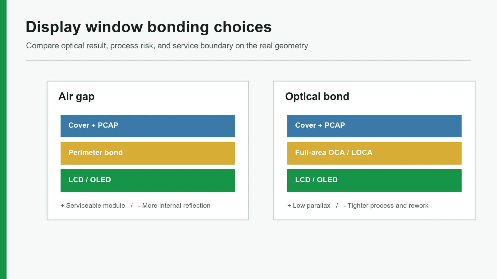
The two common constructions differ at the interface between the touch/cover assembly and the display.
Perimeter-bonded air-gap stack
User / ambient light
Cover lens + printed black mask
PCAP sensor and its lamination
Perimeter tape or gasket around the bezel
Controlled air gap across the active area
LCD front polarizer / display active area
Backlight and display module
Enclosure support frame
Full optical-bond stack
User / ambient light
Cover lens + printed black mask
PCAP sensor and its lamination
OCA, LOCA, OCR, or qualified optical silicone across the active area
LCD front polarizer / display active area
Backlight and display module
Enclosure support frame
The first construction is also called air bonding or perimeter bonding. DCL and Winstar define it as edge attachment that retains a gap over the display. Full bonding replaces that gap with a transparent material.
The optical mechanism is consistent across display manufacturers. Removing the air interface reduces internal reflection and can improve bright-ambient contrast. See Kyocera, TOPPAN, EIZO, and AMT.
For an OEM reviewing touch panels with a display window, the purchasing unit must be explicit. “Cover lens plus PCAP” and “cover lens plus PCAP plus bonded LCD” are different assemblies with different ownership, inspection, replacement, and change-control boundaries. The same distinction applies to larger display-window HMI assemblies, where the enclosure frame and gasket carry loads that the optical adhesive should not carry.
Air Gap vs PCAP Optical Bonding: The Decision Table
The fastest defensible decision is conditional. Full PCAP optical bonding usually wins on internal reflection, parallax, and cavity elimination; perimeter bonding usually wins on simple separation and lower process exposure. Neither method guarantees sunlight readability, sealing, impact survival, or touch accuracy by itself.
| Decision dimension | Perimeter-bonded air gap | Full optical bond | Boundary that decides |
|---|---|---|---|
| Internal reflection | More index transitions at glass/air interfaces | Removes the air interface; final reflection still includes cover, coatings, sensor, polarizer, and adhesive | Measure the assembled stack under defined ambient illumination |
| Ambient contrast | Often adequate indoors under controlled light | Usually favored for high ambient light | Pair the bond choice with display luminance, cover treatment, and reflection target |
| Parallax | Image plane sits farther behind the touch surface | Smaller physical separation between image and touch planes | Check oblique viewing angle, UI target size, and touch-coordinate calibration |
| Dust / condensation cavity | Retains an interlayer cavity; seal and environment govern risk | Removes that cavity but does not seal the enclosure | Define humidity, temperature change, venting, and enclosure ingress path |
| Independent service | LCD and touch/cover may be separable | Complete bonded module is normally the replacement unit | Define field-replaceable unit before releasing mechanical design |
| Specialist rework | Tape/gasket separation is often simpler | Delamination and rebonding may be possible in a controlled facility | Approve the material-specific recovery route and acceptable yield |
| Adhesive overflow | Edge adhesive stays outside the active area but can intrude if die-cut or dispense is wrong | Full-area liquid processes need volume, dam, vent, and keep-out control; film needs edge and ink-step control | Review drawing keep-outs and process capability before tooling |
| Window registration | Clear aperture can be aligned during mechanical assembly | Placement becomes locked into a laminated module | Datum the window to the display active area, not just the module outline |
| Mechanical support | Air cavity offers no distributed support | Compliant optical layer can support the stack, but it is not the enclosure mounting bond | Frame and gasket must carry clamp, drop, torsion, and fastener loads |
| Process complexity | Fewer full-area cosmetic defects; generally easier rework | Adds cleaning, lamination/dispense, de-airing, cure or autoclave, and full-area inspection | Compare validated yield and repair cost, not adhesive price alone |
| Best fit | Controlled indoor light, modular replacement, lower integration risk | High ambient light, low parallax, no internal cavity, integrated module strategy | Use project requirements rather than a blanket preference |
Choose a perimeter bond when it is good enough. A serviceable indoor controller with modest viewing angles and stable room lighting may gain little from full-area bonding. If a technician must replace the LCD without discarding the cover and PCAP, the air-gap construction may be the lower-risk system choice.
Choose a full optical bond when the interface itself is limiting performance. Outdoor kiosks, marine controls, vehicle displays, and high-ambient industrial HMIs often justify the additional process because the air interface harms contrast or the cavity creates a contamination risk.
Optical bonding is not the best choice when the service model requires component-level field replacement, the display source is likely to change without requalification, the cover geometry blocks a controlled cure, or the program cannot support full-stack prototypes and reliability tests. In those cases, a well-designed perimeter seal is more honest than an inadequately controlled optical bond.
Why the Optical Result Changes—and Why Datasheet Numbers Do Not Transfer
At each refractive-index discontinuity, part of the light is reflected. An air gap creates two additional transitions: the light exits one transparent solid into air, then enters another solid. Replacing air with a transparent adhesive whose refractive index is closer to adjacent layers can reduce those reflections. It does not remove the cover's front-surface reflection, the PCAP conductors, printed border, coatings, polarizer behavior, or ambient-light contribution.
Advantech's 2021 Industrial Display Solutions brochure illustrates the size of the possible difference: 13.5% total reflection for an air-bonded construction and 0.2% for its optical-bonding illustration (Advantech PDF). The captured brochure page does not disclose measurement geometry, wavelength, cover treatment, or complete specimen definition. Those figures are an Advantech example, not values to copy into a new product specification.
Optical-adhesive technical data are useful when their constructions and conditions remain attached:
| Public material example | Published value | Published construction / condition | What it does not prove |
|---|---|---|---|
| 3M OCA 8171CL / 8172CL | 25 / 50 µm adhesive thickness | Acid-containing acrylic film; 2018 TDS | Required bondline for a particular ink step or LCD |
| 3M OCA 817X | Refractive index 1.4876 at 405 nm, 1.4757 at 532 nm, 1.4712 at 633 nm | Metricon measurements, ±0.0005 | Complete-stack reflection across all angles and wavelengths |
| 3M OCA 8171CL / 8172CL | 0.2% / 0.3% haze | On LCD glass, ASTM D1003-92 | Haze of cover + PCAP + adhesive + finished LCD |
| Henkel LOCTITE AA 8671 PSA AD | RI 1.46 uncured / 1.48 cured; viscosity 10,000–30,000 mPa·s at 25°C | One-component UV/visible acrylic LOCA; June 2022 TDS | Compatibility with a selected polarizer, print, or plastic without trials |
| Henkel LOCTITE AA 8671 PSA AD | >99% transmission at 550 nm; 0.1% haze | 300 µm LOCA between non-alkali glasses, cured at 365 nm and 450 mW/cm² for 10 s | Transmission of a production touch-display assembly |
| AMT SOCA example | >91% transmission; RI 1.41 at 23°C/589 nm; 0.2, 0.5, 1.0 mm or thicker | Silicone-based material table; final module depends on LCD and touch specifications | A universal target or evidence that another manufacturer uses that material |
Sources: 3M OCA 817X technical data, Henkel LOCTITE AA 8671 PSA AD TDS, and AMT optical bonding.
Optical material data: compare conditions, not headline percentages
| Data sheet | Property that may help screening | Condition that must stay attached |
|---|---|---|
| 3M OCA 817X, 2018 | 0.2% / 0.3% haze for 8171CL / 8172CL | ASTM D1003-92, adhesive on LCD glass |
| Henkel AA 8671, June 2022 | >99% transmission at 550 nm and 0.1% haze | 300 µm between non-alkali glass, 365 nm cure at 450 mW/cm² for 10 s |
| AMT SOCA | >91% transmission and RI 1.41 | Silicone material at 23°C / 589 nm; final module remains display-dependent |
The procurement lesson is simple: specify the optical result at assembly level. A supplier may use adhesive data to justify material selection, but the golden sample and validation report must show how the cover, PCAP, adhesive, LCD, process, and enclosure behave together.
The Nine-Point Display-Window Evaluation Framework
1. Define an ambient optical target
A useful optical requirement names the display state, ambient condition, observation geometry, and metric. “Readable outdoors” does not. A project might compare white-state and black-state luminance under a defined directional source, or use an agreed ambient-contrast and reflection method. The same module can look excellent in a dark room and washed out beside a factory door.
IEC 62341-6-2:2015 includes methods for OLED display reflection and ambient performance, including ambient contrast. Its formal scope is OLED panels and modules. An LCD/PCAP program should cite a method from the standard only when the parties agree it applies; that reference is not blanket compliance. See IEC 62341-6-2:2015.
The drawing or validation plan defines illumination, angle, display pattern, cover treatment, measurement points, and limit for the final assembly.
A supplier quotes adhesive transmission or bare-LCD luminance as proof that the finished display is sunlight readable.
2. Check parallax at the real viewing angles
Parallax is the apparent offset between a displayed feature and the surface point above it. The error grows with physical separation and oblique viewing angle. A thick cover, sensor stack, and air gap can matter when operators view the HMI from the side or must touch small targets while wearing gloves.
AMT identifies no-air-gap bonding as a way to reduce parallax. It does not eliminate every offset. Cover thickness remains. The touch controller maps sensor coordinates; the LCD active area may be offset within its frame; the UI can introduce calibration error.
The prototype uses the intended cover thickness and is checked at the worst installation angle with the production UI target size and touch firmware.
Registration and touch accuracy are judged only from a centered camera at normal incidence.
3. Define the service unit before selecting the bond
Serviceability is an architecture decision. A perimeter-bonded module may allow the LCD and cover/PCAP assembly to separate, provided the gasket, cables, seals, and frame were designed for it. With full optical bonding, the normal replacement unit is the bonded module. A field technician should not be expected to delaminate OCA or cured LOCA beside the machine.
Optically bonded units are not automatically scrap. VIA optronics publicly describes controlled delamination, inspection, cleaning, refurbishment, and rebonding when the components are technically sound and reusable (VIA optronics). That is specialist factory rework, not evidence of a guaranteed recovery rate.
The service plan identifies the field-replaceable unit, return-to-depot route, rework owner, replacement calibration, and spare-part revision policy.
Full bonding is released while the bill of materials and service manual still treat the LCD as an independently replaceable field part.
4. Register the clear window to the LCD active area
A touch cover lens window must expose the intended pixels through its clear aperture while hiding the display bezel, adhesive edge, and assembly tolerances. The LCD module outline is a poor sole datum because the active area can have its own X/Y offset and tolerance inside that outline.
Build the tolerance chain from four layers: LCD active-area size and location, PCAP/cover fiducials, printed black-mask edge, and bonding or assembly placement. Add glass cutting, print registration, flatness, and enclosure location where they influence the visible result. Review worst-case overlap on all four sides, not only a nominal CAD overlay.
The controlled drawing shows active area, viewing area, black-mask opening, datums, basic dimensions, profile/position tolerances, and an approved illuminated border sample.
The supplier is told to “center the display in the window” without active-area coordinates or a cosmetic acceptance zone.
5. Match the adhesive form and bondline to the geometry
OCA film, LOCA/OCR liquid, and optical silicone solve different process problems. Film provides a controlled thickness but must conform over print steps and across flat surfaces without trapped air. Liquid can fill larger or variable gaps and complex shapes, but its viscosity, dispense pattern, cure access, shrinkage, and edge containment become process variables. A soft silicone can accommodate differential expansion differently from a thin acrylic film.
The public examples show why generic values fail. 3M OCA 817X is offered at 25 and 50 µm. Henkel tested AA 8671 at a 300 µm coupon thickness. AMT lists silicone-based SOCA at 0.2, 0.5, 1.0 mm or thicker. None is a default bondline for this project.
Material selection is tied to substrate chemistry, polarizer compatibility, ink-step height, panel flatness, gap map, cure path, rework strategy, operating environment, and supplier trials.
The build drawing says only “optical adhesive” and copies a TDS transmission number into the finished-product requirement.
6. Control adhesive overflow and keep-out zones
A full-area liquid bond needs enough resin to wet the intended area without reaching display FPCs, connectors, vents, bezel cavities, backlight films, or cosmetic edges. Dispense volume alone is insufficient. Viscosity, temperature, bondline, dam geometry, vent path, component bow, placement speed, and cure timing determine where the material moves.
Film processes avoid liquid flow but still need edge placement, liner control, ink-step conformity, particle control, de-airing, and allowance for adhesive squeeze or creep. Uncured excess AA 8671 can be wiped with non-polar solvent, but that cleanup instruction is not a substitute for a stable production keep-out.
The supplier returns a marked-up keep-out map, nominal dispense or film geometry, controlled bondline, edge-inspection criteria, and process-capability evidence from representative samples.
The first overflow review occurs after adhesive reaches the polarizer edge or connector area on pilot units.
7. Separate the optical interface from the enclosure load path
Full bonding creates a more integrated stack, but the optical layer should not become the unexamined answer to enclosure loads. Optical adhesive should not serve as the mechanical mounting bond. The housing, support frame, bezel, and gasket must manage fastener clamp, cover impact, chassis twist, drop, vibration, and thermal expansion (UICO).
A rigid clamp around a bonded LCD can transfer cover deflection into the cell, causing mura, polarizer stress, edge lift, or touch drift. An air-gap stack has a different risk: unsupported cover flex can change spacing or contact the display. Both need a defined load path.
Mechanical analysis and prototype tests show support locations, gasket compression, clamp limits, component clearances, and worst-case thermal movement.
The optical adhesive is described as structural support while enclosure drawings omit load and compression limits.
8. Convert the environment into test conditions
Temperature, humidity, solar/UV exposure, cleaning chemistry, vibration, altitude, and operating heat affect the interface differently. The requirement should describe the installed product, not borrow a single adhesive coupon result.
3M reports no appreciable visible deterioration after 800 hours at 65°C/90% RH for specified LCD-glass/8172CL/polymer constructions. Henkel reports no delamination, >98% transmission at 550 nm, and 0.1% haze after 1,000 hours at 85°C/85% RH for a 300 µm glass/AA 8671/glass coupon cured under its stated condition. Both manufacturers label the data as typical or reference information and assign application suitability to the user. These results help shortlist materials; they do not qualify an HMI.
IEC 60068-2-14:2023 supplies change-of-temperature methods, while IEC 60068-2-78:2025 covers damp heat, steady state, without condensation (IEC 60068-2-14, IEC 60068-2-78). The project still sets severities, duration, operating state, recovery, sample size, and pass/fail limits.
The qualification matrix maps each use condition to a test method and post-test optical, cosmetic, touch, and electrical limits.
A report says “IEC 60068 passed” without edition, method, severity, samples, or acceptance criteria.
9. Lock the golden sample and change-control boundary
A display-window stack can change even when the outer drawing number does not. LCD polarizer revisions, backlight bins, cover coatings, black ink, PCAP pattern, adhesive formulation, release liner, cure source, lamination equipment, and firmware can alter appearance or touch behavior.
The approved sample therefore needs a supporting record: component manufacturers and revisions, material family, controlled process, inspection report, optical data, touch firmware, and photographs under agreed lighting. The purchase specification should define which changes require notice and revalidation.
Production release links the golden sample to a controlled bill of materials, process flow, measurement report, cosmetic standard, and supplier-change notification list.
The supplier may substitute a “technically equivalent” LCD or adhesive without repeating window-registration, optical, touch, and environmental checks.
Failure Chain: From Drawing or Process Error to Field Symptom
The same field complaint can begin at different points. A washed-out image may come from the bond choice, the cover coating, a polarizer change, or a measurement mismatch. The table keeps cause and control together.
| Input or process error | Physical mechanism | Observable symptom | Design or approval control |
|---|---|---|---|
| Air gap retained under high ambient light | Extra solid/air interfaces reflect incident and display light | Low black-state contrast, glare, apparent washout | Assembly-level reflection/ambient-contrast test under defined geometry |
| Clear aperture positioned from module outline only | Active area offset and assembly tolerances consume border overlap | Uneven black border, clipped pixels, visible bezel edge | Datum to active area; worst-case tolerance stack; illuminated sample |
| Liquid volume or dam window not controlled | Resin reaches a prohibited edge or leaves incomplete fill | Overflow, void, edge bubble, contaminated connector/polarizer | Keep-out map, dispense window, bondline control, edge inspection |
| OCA too thin for print step or bow | Adhesive cannot conform and wet the full interface | Bubbles or whitening near black mask | Measure ink step and flatness; choose conformable material and de-air process |
| Enclosure clamp loads the bonded cell | Stress passes through cover and adhesive to LCD | Mura, edge lift, touch drift, fracture | Defined frame support and gasket compression; mechanical test |
| Service plan assumes component separation | Bonded module cannot be safely opened in field | Long outage or unintended full-stack scrap | Set replaceable unit and depot-rework route before release |
| Material or LCD revision changes silently | Optical, dimensional, thermal, or electrical behavior shifts | Color/brightness mismatch, new bubbles, registration or touch failure | Controlled BOM, change notice, risk-based revalidation |
Six Steps to Review and Approve the Cover Lens and Display Stack
Step 1 — Freeze the use conditions and service boundary
Record installation angle, ambient-light range, minimum readable content, touch target size, glove/water behavior, temperature/humidity exposure, cleaning agents, vibration, expected enclosure ingress path, and replaceable unit. Include display duty cycle and internal temperature if the backlight or processor heats the cavity. This step decides whether the problem is optical, environmental, service-driven, or a combination.
Step 2 — Exchange source drawings, not screenshots
Provide the LCD mechanical drawing with active area, viewing area, polarizer outline, bezel, FPC, connectors, vents, and keep-outs. Add the cover-lens outline, glass type and thickness, edge treatment, black-mask artwork and tolerances, surface treatments, PCAP sensor/flex details, enclosure datums, gasket, and clamp scheme. A screenshot of the front view cannot support a tolerance analysis.
The custom capacitive touch panel design guide provides related input categories, while the present review must go further by tying them to the selected LCD and optical interface.
Step 3 — Compare both constructions on the actual geometry
Build a nominal and worst-case section for perimeter bonding and full bonding. For the air-gap option, define gasket width, compression, venting or cavity strategy, cover deflection, and separation from the LCD. For the optical option, define adhesive form, target bondline, ink-step accommodation, cure or autoclave access, dam/vent concept, overflow keep-outs, and assembly support. Reject any concept that depends on an unspecified “clear glue.”
Step 4 — Approve representative engineering samples
Samples should use the intended cover material, print, PCAP stack, LCD revision, bonding process, enclosure support, and touch firmware. Inspect them powered off and on, under front and oblique lighting, at the defined viewing angles. Record bubbles, particles, Newton-ring-like artifacts if present, edge appearance, black-mask overlap, display centering, color uniformity, touch mapping, and cosmetic boundaries.
Step 5 — Run the project validation matrix
Test the complete assembly, not only adhesive coupons. Establish baseline optical, cosmetic, touch, and electrical data before exposure; repeat the same measurements after temperature change, damp heat, vibration/shock, cleaning, UV/solar exposure, or other project-specific stresses. Use testing and quality controls that identify the specimen, method, equipment, conditions, sample count, recovery, and acceptance limits.
Step 6 — Release the production and change-control package
The release set needs controlled drawings, a bill of materials, an adhesive-family or approved-equivalent rule, and the process flow. Add critical parameters, the inspection method, cosmetic standard, golden sample, validation report, packaging requirements, and revalidation triggers. State whether a display end-of-life replacement requires optical and touch reapproval. If the complete bonded module is the spare part, assign its own service number and calibration instructions.
Approval flow and release evidence
| Gate | Required output | Release question |
|---|---|---|
| Requirements | Use-condition and service-boundary record | Is the choice driven by a measurable need? |
| Drawing review | Datum scheme, tolerance stack, keep-out map | Can the window, active area, and adhesive edge coexist at worst case? |
| Engineering sample | Representative bonded and/or air-gap units | Does the actual geometry meet optical, cosmetic, and touch targets? |
| Qualification | Baseline and post-exposure report | Do IEC methods and project stresses have explicit acceptance limits? |
| Production release | Golden sample, controlled BOM/process, change triggers | Can a future lot or substitute be compared to the approved state? |
Validation and Sample-Approval Matrix
Standards provide methods; the product specification provides the stress and pass/fail rule. The matrix below deliberately leaves universal severities out because a 7-inch indoor control, a marine HMI, and a vehicle display do not share one valid profile.
| Check | Baseline / exposure | Record before and after | Example acceptance form |
|---|---|---|---|
| Window registration | Powered display with border and full-field patterns; normal and worst viewing angle | Active-area overlap on four sides; pixel clipping; bezel/adhesive visibility | Within drawing tolerance; no prohibited edge visible |
| Reflection / ambient contrast | Defined directional and/or diffuse illumination, geometry, display state | Reflected luminance or agreed metric; white/black state | Project numeric limit under stated setup |
| Luminance and uniformity | Production backlight setting, warm-up, measurement grid | Center luminance, uniformity, color coordinates if required | Change from baseline plus absolute minimum |
| Haze / transmission | Material coupon for incoming control and/or assembled stack where method is suitable | Method, wavelength/illuminant, specimen construction | Material and assembly limits kept separate |
| Cosmetic bond inspection | Powered off/on; specified lighting and distance | Bubble/particle count and size, edge void, whitening, overflow, print defects | Zoned cosmetic standard with size/count limits |
| Touch mapping | Intended firmware, cover, grounding, glove/water modes as applicable | Coordinate error, missed/false touches, edge performance | Project-defined grid and functional criteria |
| Change of temperature | IEC 60068-2-14:2023 method selected with project severities | Bubbles, delamination, mura, registration, touch, optical shift | No critical defect; numeric shift limits stated |
| Damp heat, steady state | IEC 60068-2-78:2025 method with project temperature/RH/duration | Haze, bubbles, delamination, corrosion, touch and electrical function | Condition-specific visual and functional limits |
| Mechanical exposure | Project vibration, shock, drop, torsion, or clamp test | Glass damage, edge lift, display artifacts, touch, fasteners/gasket | No safety/functional failure; cosmetic limits stated |
| Cleaning / chemical | Named fluid, concentration, cloth, force, strokes, dwell, temperature | Coating damage, print attack, edge ingress, haze, touch | No prohibited change against baseline |
| Rework trial, if required | Approved delamination or gasket-replacement process | Component recovery, contamination, optical/touch result | Defined reusable-component criteria and revalidation |
A test report is complete only when another engineer can identify what was tested and reproduce the setup. “No visible change” needs an inspection condition. “Touch passed” needs firmware, grounding, stimulus, grid, and acceptance rule.
Sample approval record
| Approval record | Minimum identification |
|---|---|
| Optical setup | Illuminance/source, geometry, camera or meter, display pattern, backlight state |
| Cosmetic setup | Powered state, viewing distance, angle, light source, defect zones and limits |
| Touch setup | Controller and firmware revision, grounding, stimulus, grid, glove/water mode |
| Environmental specimen | LCD, cover, PCAP, adhesive, process lot, enclosure support, baseline results |
Project Input and Drawing Checklist
Use this list before requesting a stack review or sample build.
Optical and display inputs
- [ ] LCD manufacturer, model, revision, lifecycle status, and full mechanical/optical datasheet
- [ ] Active area, viewing area, module outline, polarizer outline, bezel, FPC, vents, and keep-outs
- [ ] Required luminance, ambient condition, observation angle, contrast/reflection target, and display patterns
- [ ] Cover material and thickness; clear, AG, AR, AF, hard-coat, privacy, or other treatment
Touch cover lens window inputs
- [ ] PCAP sensor construction, controller, firmware ownership, flex exit, grounding, glove/water requirements
- [ ] Black-mask artwork, ink system, print-step height, color/gloss target, and registration tolerance
- [ ] Clear-aperture and cosmetic zones tied to LCD active-area datums
- [ ] Cover edge finish, holes/cutouts, logo or indicator windows, and allowable distortion
Bonding, enclosure, and service inputs
- [ ] Perimeter and full-bond concepts compared on one cross-section
- [ ] Proposed OCA/LOCA/OCR/silicone family, bondline basis, cure/autoclave path, and substrate compatibility
- [ ] Adhesive overflow keep-outs, dam/vent concept, edge inspection, and particle/bubble criteria
- [ ] Enclosure frame, gasket, fasteners, compression limits, cover support, and thermal movement
- [ ] Field-replaceable unit, depot-rework route, spare strategy, and calibration after replacement
- [ ] Validation matrix, golden-sample record, controlled BOM, and change-notification triggers
Release Blockers That Should Stop Release
- “Sunlight readable” has no illumination or contrast condition. The phrase cannot be verified against an assembled unit.
- The viewing window is dimensioned only from the LCD module outline. Active-area offset and print/placement tolerances remain uncontrolled.
- A full bond is selected before the field-replaceable unit is defined. Service cost is being deferred, not solved.
- The drawing specifies only “optical adhesive.” Material form, substrate fit, bondline, cure, ink step, and environment are unresolved.
- Adhesive transmission is treated as complete-stack transmission. The cover, sensor, coatings, polarizer, interfaces, and measurement method are missing.
- No keep-out protects the polarizer edge, FPC, connector, or vent. Overflow and creep have no controlled boundary.
- The optical adhesive is expected to mount the display in the enclosure. Clamp and impact loads lack a designed structural path.
- An LCD or adhesive substitution needs no revalidation. Registration, appearance, thermal stress, and touch behavior can change despite a nominally similar part.
Frequently Asked Questions
What is the best construction for a capacitive touch display window?
There is no universal best construction. Full optical bonding is usually favored for high ambient light, low parallax, and removal of the internal cavity. A perimeter-bonded air gap is often better for controlled indoor lighting and independent component replacement. Validate the complete cover, PCAP, LCD, enclosure, and firmware stack.
What is the difference between air bonding and PCAP optical bonding?
Air bonding attaches the touch/cover assembly around the bezel and leaves a gap over the LCD. PCAP optical bonding fills that gap with OCA, LOCA, OCR, or another qualified transparent material. The full bond can reduce internal reflections but adds full-area process, inspection, and repair requirements.
Does optical bonding eliminate all display reflection?
No. Optical bonding removes the air interface between selected layers, but the cover's front surface, coatings, PCAP conductors, adhesive interfaces, and LCD polarizer still affect reflection. Specify and measure the assembled stack under defined ambient illumination and viewing geometry rather than adopting a generic percentage.
Does optical bonding make a touch display waterproof?
No. Filling the display-to-touch gap removes one internal cavity; it does not seal the enclosure, connectors, flex exits, fasteners, vents, or cover-to-housing joint. Any ingress-protection claim belongs to the finished enclosure and its applicable verification, not to optical bonding alone.
Can an optically bonded LCD be repaired?
Sometimes, but not as routine field work. A qualified facility may delaminate, inspect, clean, and rebond an assembly if the LCD, cover, and sensor remain reusable. The project should define the complete bonded module as the normal field replacement and document any depot-level recovery route separately.
How should a touch panel display window be aligned to the LCD?
Align the clear aperture and black-mask border to the LCD active area using controlled datums and a worst-case tolerance stack. Include active-area offset, print registration, cover machining, PCAP fiducials, bonding placement, and enclosure location. Do not rely only on the display module's outer frame.
How is adhesive overflow controlled in a touch cover lens window?
Control starts with prohibited-area keep-outs, bondline and flatness data, then a material-specific film geometry or liquid volume, dispense, dam, vent, placement, and cure window. Inspect representative edges after bonding. No universal clearance replaces process trials on the actual cover, PCAP, and display geometry.
Which tests should approve an optical display stack?
Use assembly-level optical, registration, cosmetic, touch, electrical, environmental, mechanical, and cleaning checks. IEC 60068-2-14:2023 and IEC 60068-2-78:2025 can supply temperature-change and steady damp-heat methods, but the project must set severities, sample count, operating state, recovery, and acceptance limits.
Review the Cover Lens and Display Stack
The bond choice should follow four decisions: the required optical result, the active-area and black-mask tolerance stack, the field-replaceable unit, and the validation conditions. Once those are fixed, OCA, LOCA, OCR, optical silicone, or a perimeter gasket can be evaluated against a real geometry rather than a generic preference.
JASPER is one manufacturer option for reviewing a cover lens, projected-capacitive sensor, display window, and HMI assembly. A useful review package contains the LCD drawing and revision, cover artwork, PCAP requirements, enclosure section, service boundary, use environment, and acceptance matrix. The concrete next step is to review the cover lens and display stack before tooling or display source approval.
Technical References
- Source: 3M Optical Clear Adhesive Technical Data. Accessed 2026.
- Source: DuPont Optical Bonding Material Guidance. Accessed 2026.
- Source: IEC 60068-2-14:2023 Change of Temperature. Accessed 2026.
- Source: IEC 60068-2-78:2025 Damp Heat Testing. Accessed 2026.
- Source: Display Manufacturer Active Area and Polarizer Drawings. Accessed 2026.
- Source: Kyocera. Accessed 2026.
- Source: TOPPAN. Accessed 2026.
- Source: EIZO. Accessed 2026.
- Source: Advantech PDF. Accessed 2026.
- Source: 3M OCA 817X technical data. Accessed 2026.
- Source: Henkel LOCTITE AA 8671 PSA AD TDS. Accessed 2026.
- Source: AMT optical bonding. Accessed 2026.
- Source: IEC 62341-6-2:2015. Accessed 2026.
- Source: VIA optronics. Accessed 2026.
- Source: UICO. Accessed 2026.
- Source: IEC 60068-2-14. Accessed 2026.
- Source: IEC 60068-2-78. Accessed 2026.
Review the complete capacitive touch stack before release
Send the cover, artwork, active area, display, electrode, controller, tail, environment, and acceptance states for an engineering review.