
A graphic overlay is the printed operating surface aligned to displays, controls, legends, and tactile features. It does not create electrical switching, structural support, ingress protection, or finished-device compliance by itself.
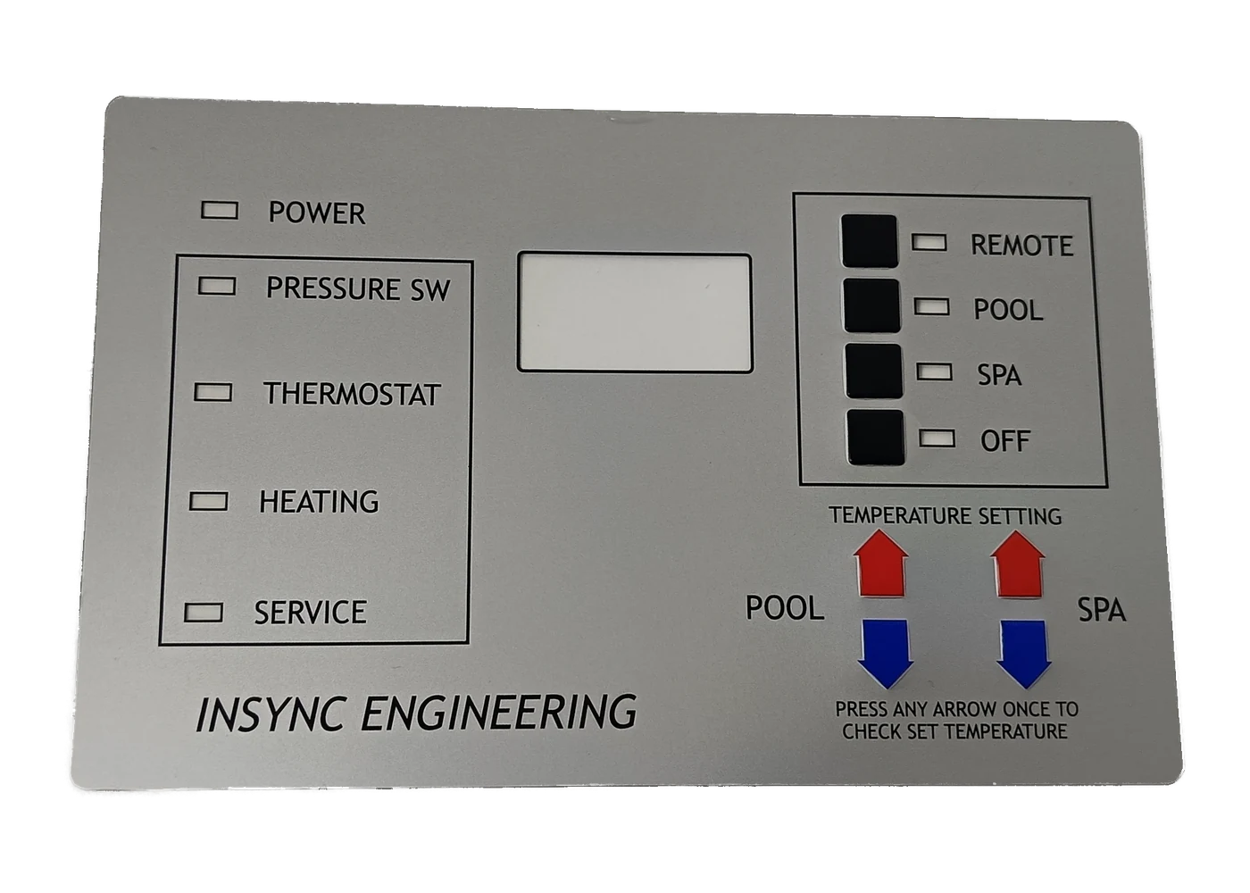
1. What Is a Graphic Overlay? Definition and Canonical Anatomy
A graphic overlay is a decorated surface fitted over a housing, control panel, keypad, display, or switch assembly. It carries legends, symbols, colors, windows, and control locations. It may provide a cleanable wear surface and mounting boundary. Alignment with the interface—not circuitry—defines it.
This graphic overlay definition is functional.
JASPER’s graphic overlays page separates four decisions that belong in the part definition: substrate, printing, surface features, and mounting. Its custom overlay definition also draws the electrical boundary directly: the part may be a standalone adhesive-backed face or the top layer of a membrane switch, but it does not create electrical switching by itself.
A common installed stack
The construction below is canonical, not universal. A metal faceplate, adhesive-free insert, first-surface print, or molded decoration can move the project into a different product family.
OPERATOR / CLEANING / AMBIENT EXPOSURE
Optional hardcoat, gloss, matte, or texture · Use surface
Transparent PET or PC film · Shape, feel, optical path
Second-surface graphics · Legends, masks, color, opacity
Selective or full pressure-sensitive adhesive · Mounting; keep-outs where specified
Product housing / bezel / switch assembly · Structural and sealing counterpart
RELEASE LINER REMOVED AT ASSEMBLY
Second-surface, or reverse, printing puts the ink behind transparent film. 3M’s current 467MP technical data lists subsurface-printed polyester and polycarbonate overlays as graphic-attachment applications. MacDermid Alpha’s industrial-film literature describes the same separation of graphics from direct touch and cleaning.
That arrangement protects the print face from direct contact; it does not make the complete stack immune to solvent attack, edge ingress, adhesive lift, UV change, or abrasion. Those outcomes depend on the named film grade, coating, ink, adhesive, geometry, environment, and installed assembly.
2. What Does a Control Panel Graphic Overlay Do?
A control panel graphic overlay coordinates information, touch location, optics, surface exposure, and mounting in one converted part. Each function has a limit, and assigning the limit to the correct layer prevents bad specifications.
- Information: legends, zones, warnings, model data, and symbols; not automatic regulatory compliance.
- Optics: clear, tinted, diffusing, masked, or dead-front areas; not readability under every light, angle, or exposure.
- Location cues: embossing or texture that helps a finger find a control; not electrical actuation, force, travel, or switch life.
- Surface protection: film/coating over reverse print; not a universal chemical, abrasion, outdoor-life, or impact rating.
- Mounting: adhesive coverage, cutouts, keep-outs, perimeter, and housing alignment; not enclosure ingress protection.
For icons, start with IEC 60417 for electrotechnical equipment and ISO 7000 for registered equipment symbols. Sector-specific safety, language, accessibility, and end-product rules still apply.
Covestro’s Makrofol and Bayfol selector lists distinct graphic, diffusing, reflective, scratch-resistant, optical, and black-panel grades. “Clear PC” or “black window” is not a finished optical specification.
3. Graphic Overlay vs. Label, Nameplate, and Membrane Switch
A graphic overlay belongs in the operating interface when its artwork or geometry must register to controls, windows, indicators, or tactile features. A label or nameplate can share films, inks, and adhesives, while a membrane switch can use an overlay as its top layer. The release drawing must still identify which product family owns function below the surface.
Function decides.
| Part family | Primary job | Typical construction boundary | Electrical function? | Choose it when | Do not assume |
|---|---|---|---|---|---|
| Durable label | Identify, warn, rate, serialize, or instruct | Printed stock or film attached to a surface | No | Information is the main deliverable and does not need a complete control-layout interface | Every label is suitable for permanent safety marking or UL 969 use |
| Nameplate / rigid faceplate | Identify equipment and sometimes provide a stiff visible panel | Metal, acrylic, rigid plastic, glass, or another self-supporting part; adhesive or mechanical mounting | Usually no | Rigidity, structural appearance, metal finish, thick optical window, or mechanical fastening matters | “Nameplate” and “overlay” have identical stiffness, processing, or regulatory scope |
| Graphic overlay | Present the operating surface and align graphics/features to the device beneath | Decorated film or thin panel, often reverse printed and adhesive mounted | No, by itself | Legends, windows, controls, touch zones, or tactile cues must register as one interface | The part alone creates switching, structural support, ingress rating, or finished-device compliance |
| Membrane switch | Provide a low-profile electrical switching assembly with a visible interface | Graphic overlay plus spacer, contacts, printed/flexible circuits, tail, adhesive, and optional domes/backlighting | Yes | Pressing a defined area must change an electrical circuit state | The visible overlay represents the electrical stack or its performance |
Terminology varies, so function resolves the boundary. A released item ending at film, print, adhesive, and cut geometry is normally an overlay; a part that must close a circuit needs a membrane-switch contact stack. The related JASPER overlay-versus-switch guide covers that handoff. For required markings, the UL program evaluates a defined stock, print, adhesive, surface, temperature, and exposure combination—not an arbitrary constituent or complete control panel.
4. Materials, Printing, Windows, Embossing, and Adhesive
Material selection for an industrial graphic overlay is a stack decision. Grade matters. Mylar’s electronics brochure separates PET grades by optical state, stabilization, and print pretreatment; Covestro separates PC grades by finish, forming, UV, scratch, die-cutting, and optics. Neither resin acronym is a release-ready specification.
Worked stack example: A 250 µm (10 mil) face film with 0.127 mm (5 mil) PSA produces a pre-ink/coating stack of 0.377 mm, rounded to about 0.38 mm. Covestro lists 250 µm among established graphic-film gauges, while 3M publishes 0.127 mm for 468MP. This calculation demonstrates stack arithmetic for two named supplier values; it is not JASPER data or a default construction. The released film, adhesive, inks, coatings, housing, and environment determine the actual build.
| Decision | Use this path when | Verify on the first article | “Not sufficient” wording |
|---|---|---|---|
| PET film | The selected PET grade fits the flexing, chemical, dimensional, print, and optical requirements | Exact grade, thickness, treated print side, finish, edge behavior, emboss response, cleaner exposure | “Use polyester because it is always more durable” |
| PC film | A specific PC grade supplies the required forming, finish, optical, processing, or appearance behavior | Exact grade, gauge, surface on each side, ink/cure compatibility, stress and cleaner exposure | “Use polycarbonate because it is impact resistant” |
| Hardcoat / texture | The use surface needs defined glare, feel, scratch, abrasion, or chemical behavior | Coating family, gloss/texture reference, cleanability, embossability, window effect, test method and limit | “Hardcoated” or “chemical resistant” without conditions |
| Reverse print | Graphics should sit behind the film use surface | Ink series, cure, opacity, color standard, intercoat adhesion, adhesive interaction, edge exposure | “Subsurface print is permanent” |
| Display window | A display, lamp, sensor, or dead-front legend must be viewed through the overlay | Active area, clear opening, mask, adhesive keep-out, haze/transmission, tint, lit/unlit contrast and viewing angle | “Clear window” or “dead front” without optical targets |
| Embossing / texture | A feature should help locate a key, icon, rail, or zone | Shape, alignment, film strain, appearance, installed feel, surrounding flatness and downstream control behavior | “Tactile” as a substitute for switch force, travel, or snap |
| Mounting adhesive | The actual housing, contour, edge and environment are known | Adhesive family, thickness, die-cut pattern, surface preparation, pressure, dwell, peel/shear plan, removal needs | “Use 3M adhesive” without a product and substrate |
MacDermid Alpha’s Autoflex EB illustrates the grade rule: its hardcoat, finish, embossing, resistance, and primer options belong to that named family, not every PET film.
Windows require an optical drawing
A window needs separate callouts for the active display, clear opening, printed mask, adhesive keep-out, and housing opening. The JASPER display-window workflow checks off, on, angled, and post-exposure states. ASTM D1003-21 measures haze and luminous transmittance; it does not prove readability, color, concealment, or uniform illumination.
Embossing is a geometry, not a life claim
Pillow, rim, rail, and raised-icon forms strain different areas. Approve them over the actual actuator and support: a free film sample can feel different after lamination, and embossing does not create switch snap.
Adhesive starts with the housing
3M positions 467MP for metal/high-surface-energy plastics and 9653LE for many low-surface-energy plastics and powder coatings. They are screening examples, not JASPER defaults. Resin or coating, texture, curvature, contamination, edge load, pressure, dwell, and exposure decide the actual adhesive.
5. How a Graphic Overlay Is Made—and Where Failures Start
Graphic-overlay manufacturing capabilities convert an interface definition into registered layers, cut geometry, and an approval record. Printing is only one operation; most preventable failures begin when the drawing, housing, environment, or acceptance state is incomplete.
Print is not the process.
- Collect inputs: housing revision, datums, controls, displays, environment, cleaners, and required records.
- Control artwork: separate legends, masks, windows, texture, cuts, embossing, adhesive, and keep-outs.
- Name the stack: film grade/gauge, surfaces, coating, ink, adhesive, liner, and optical layers.
- Print and cure: control order, opacity, registration, color, cure, and compatibility through the printing process.
- Laminate and convert: apply the adhesive pattern and cut without contaminating optical or bond zones.
- Inspect in context: install on production-intent hardware; power displays and operate controls.
- Release records: freeze artwork, stack, sample, tests, packaging, installation, and change triggers.
Two common failure chains
UNKNOWN HOUSING / WRONG ADHESIVE FAMILY
incomplete wet-out or weak bond at texture/edge
edge lift under handling or exposure
dirt or liquid reaches the interface boundary
cosmetic failure, control interference, or enclosure-test failure
UNDEFINED CLEANER OR WINDOW STATE
film, coating, ink, or adhesive is screened under the wrong condition
haze, gloss change, print attack, edge damage, or bond loss appears later
legends or displays no longer meet the approved appearance
material substitution alone does not solve the missing test definition
The chains show why “industrial grade” and “chemical resistant” are not engineering inputs; they do not predict a failure.
6. Validate the Stack, Not a Marketing Adjective
Graphic-overlay validation needs a representative stack, housing, exposure, method, and acceptance rule. A standard names a procedure or scope; it rarely supplies the pass value.
A method is not a result.
| Risk / decision | Suitable evidence path | What the test plan must state | Boundary |
|---|---|---|---|
| Outline, cutout, window, and emboss registration | Controlled drawing plus dimensional/visual inspection on the first article | Datums, dimensions, tolerance, sampling, gauge or vision method, installed reference | A supplier’s generic tolerance is not the product tolerance |
| Clear or dead-front window | ASTM D1003-21 where haze/transmittance is relevant, plus powered visual review | Instrument geometry, specimen, light state, ambient light, viewing angle, color/contrast criterion | Optical numbers alone do not prove display readability |
| Adhesive peel | ASTM D3330/D3330M-04(2025), using the actual surface when appropriate | Method letter, peel angle/rate, surface, preparation, dwell, conditioning, minimum and failure mode | Peel force alone may not predict edge lift or field function |
| Ink or coating attachment | ISO 2409:2020 or ASTM D3359-23 when the coating/substrate fits the method | Cut method, coating thickness, texture, tape, conditioning, rating and failure layer | Cross-cut/tape ratings are not absolute adhesion strength |
| Transparent surface abrasion | ASTM D1044-24 when its specimen and optical method fit | Abrader, load, cycles, cleaning, haze change and appearance limit | Lab cycles do not equal finger presses, wipes, or years |
| Coating abrasion on a rigid plane | ASTM D4060-25 where applicable | Coating/substrate, wheel, load, cycles, resurfacing and evaluation | Flexible or embossed overlays may require another fixture or method |
| Cleaner / chemical exposure | Defined OEM wipe sequence; ISO 2812-1:2017 where liquid immersion is relevant | Chemical identity, concentration, temperature, dwell, wipe material/force, cycles, rinse/recovery and acceptance | “Resistant to cleaners” has no testable meaning by itself |
| UV and moisture exposure | ISO 4892-3:2024 for plastics or ASTM G154-23 with a defined cycle | Lamp, irradiance, temperature, water/condensation, duration, controls, color/gloss/adhesion criterion | Exposure hours cannot be converted directly into outdoor years |
| Permanent safety marking | ANSI/UL 969 only when the end product and marking system require it | Recognized construction, ink, adhesive, surface, temperature, exposure and Conditions of Acceptability | A recognized film or adhesive does not certify the finished overlay |
| Dust and water ingress | IEC 60529 on the complete enclosure/assembly | Exact configuration, seals, fasteners, openings, conditioning, test level and report | The loose overlay has no independent enclosure IP rating |
ASTM D3330 peel data do not map directly to function and the method permits a representative surface in certain comparisons. ASTM G154 requires reported operating conditions and does not select the correct exposure. Both limits belong in the test plan.
ASTM’s current electronics catalog lists F1598, F1842, F1843, F2357, F2592, and F2865 as withdrawn. A legacy report may name a historical version; a new RFQ should not call it current.
IEC 60529 classifies an enclosure, not loose film. JASPER’s testing page gives the companion rule: a component check is not finished-product certification.
7. Where Industrial Graphic Overlays Fit—and When They Do Not
Industrial graphic overlays fit products that need a thin, custom, registered operating face without asking that face to carry structural or electrical work. The same construction can appear in several sectors, but each sector changes the validation boundary.
| Context | Why an overlay can fit | Boundary to define before release |
|---|---|---|
| Industrial controls and instruments | Consolidates legends, status windows, control zones, scales, and a cleanable face | Oils, cleaners, gloves, glare, edge exposure, control alignment, service access |
| Medical equipment interfaces | Creates a readable operator surface and can place print behind a film | Component manufacture is separate from finished-device usability, cleaning validation, biocompatibility, electrical safety, risk management, and regulatory approval |
| Automotive and transport interiors | Supports registered icons, indicators, textures, and backlit zones | Vehicle-specific material, flammability, optical, chemical, temperature, UV, vibration, assembly, and change-control requirements |
| Marine and outdoor equipment | Can combine legends, windows, film/coating options, and an adhesive boundary | Salt, sunlight, temperature, moisture paths, pressure changes, enclosure design, and assembly-level ingress testing |
| Appliances and commercial equipment | Integrates brand graphics, instructions, key locations, and display windows | Cleaner list, heat/steam, greasy soils, abrasion, repeated operation, and service replacement |
A flexible overlay is not the best choice when the face must carry load, resist heavy impact, bridge a large opening, supply rigid-panel stiffness, or close a circuit. Frequently changing information may belong on a replaceable label/display; a deep 3D surface may favor molded decoration; a gouge-prone window may need a lens or bezel. Gaskets, fasteners, connectors, and housing joints remain enclosure requirements.
8. Project Input and Sample Approval Checklist
A release-ready control panel graphic overlay starts with a controlled interface package, not a logo file and the phrase “make it durable.” The checklist below turns the engineering boundary into reviewable inputs.
Part and artwork
- [ ] Housing revision, 2D/3D data where needed, and one datum scheme
- [ ] Outline, radii, openings, windows, edge clearances, and orientation
- [ ] Vector artwork, outlined fonts, approved symbols, language/version, and colors
- [ ] Separate mask, translucent, window, texture, emboss, adhesive, and keep-out layers
Interface and environment
- [ ] Display active area, bezel, viewing angle, ambient light, lit/unlit state, and leakage limit
- [ ] Control type, actuator, touch method, gloves, accessibility, and tactile cues
- [ ] Housing material/coating, texture, curvature, contamination, and assembly process
- [ ] Temperature/humidity, outdoor exposure, named cleaners, wipe method, abrasion, and impact
Approval and release
- [ ] Exact film, coating, ink, adhesive, and liner—or controlled substitution rules
- [ ] First article on production-intent hardware, powered and operated
- [ ] Test matrix: specimen, method, condition, limit, sample size, and failure report
- [ ] Cosmetic reference, packaging/liner, storage, installation, and change triggers
The next step is to review the overlay boundary for the product. If the part must remain a standalone face, custom graphic overlays are the relevant JASPER option. If it must switch, sense, carry load, or establish a seal, move that requirement to the correct assembly before artwork approval.
9. Frequently Asked Questions
What is a graphic overlay on a control panel?
A graphic overlay is the decorated physical face aligned to a control panel’s legends, controls, indicators, and display windows. It may include film, reverse-printed graphics, surface texture, embossing, cutouts, and mounting adhesive. It does not contain an electrical switching circuit by definition.
Is a graphic overlay the same as a membrane switch?
No. A graphic overlay can be the visible top layer of a membrane switch, but the complete switch adds spacer, contact, circuit, tail, adhesive, and optional dome or lighting layers. A standalone overlay identifies and protects the interface; it does not close an electrical circuit.
What is the difference between a graphic overlay, a label, and a nameplate?
A graphic overlay normally registers to an operating interface. A label primarily identifies, warns, or instructs. A nameplate often provides identification on a rigid or self-supporting face. Materials and attachment methods can overlap, so the released function—not the supplier’s preferred term—should decide the category.
Is PET or polycarbonate better for an industrial graphic overlay?
Neither material family is universally better. The decision requires a named grade, thickness, coating, print surface, forming or embossing need, window requirement, cleaner list, UV condition, adhesive, housing, and validation plan. A resin acronym alone cannot predict the installed result.
How are graphics protected on a reverse-printed overlay?
Reverse printing places ink on the back of a transparent film, so the film separates the graphics from direct touch and wiping. That arrangement reduces direct exposure; it does not make the ink, film edges, coating, or adhesive immune to chemicals, abrasion, moisture, or ultraviolet radiation.
Can a graphic overlay make a control panel IP65?
Not by itself. IEC 60529 assigns an IP code to the tested enclosure configuration. Overlay edges, adhesive, openings, housing joints, gaskets, fasteners, connectors, vents, and installation all affect ingress. Claim an IP level only for the assembly and conditions covered by the test evidence.
What must be specified for a display window or dead-front legend?
Define the active display, clear opening, printed mask, adhesive keep-out, housing bezel, haze or transmission target, tint, lit and unlit contrast, viewing angle, ambient light, cosmetic limits, and post-exposure acceptance. “Clear,” “smoke,” or “dead front” alone is not an optical specification.
What should an OEM send for graphic-overlay sample approval?
Send controlled housing and overlay drawings, vector artwork, datums, colors, windows, control locations, embossing, adhesive coverage, housing material and finish, environment, cleaners, optical states, test requirements, and production-intent hardware. Approve the sample installed, illuminated, operated, cleaned, and inspected under defined conditions.
Release the overlay as an installed interface
Send the housing drawing, vector artwork, windows, controls, embossing, adhesive coverage, materials, cleaners, optical states, environment, and production-intent hardware for a boundary review.