
Seat occupancy sensor resistance cannot be accepted from one ohmmeter reading. An OEM should specify the unloaded state, defined loaded state, and post-release state, together with the seat stack, loading area, hold time, measurement circuit, and separate acceptance windows. A practical starting protocol uses a 10-second loaded hold at 23 ± 2°C; the final limits must come from the actual seat and controller interface, not a universal resistance value.
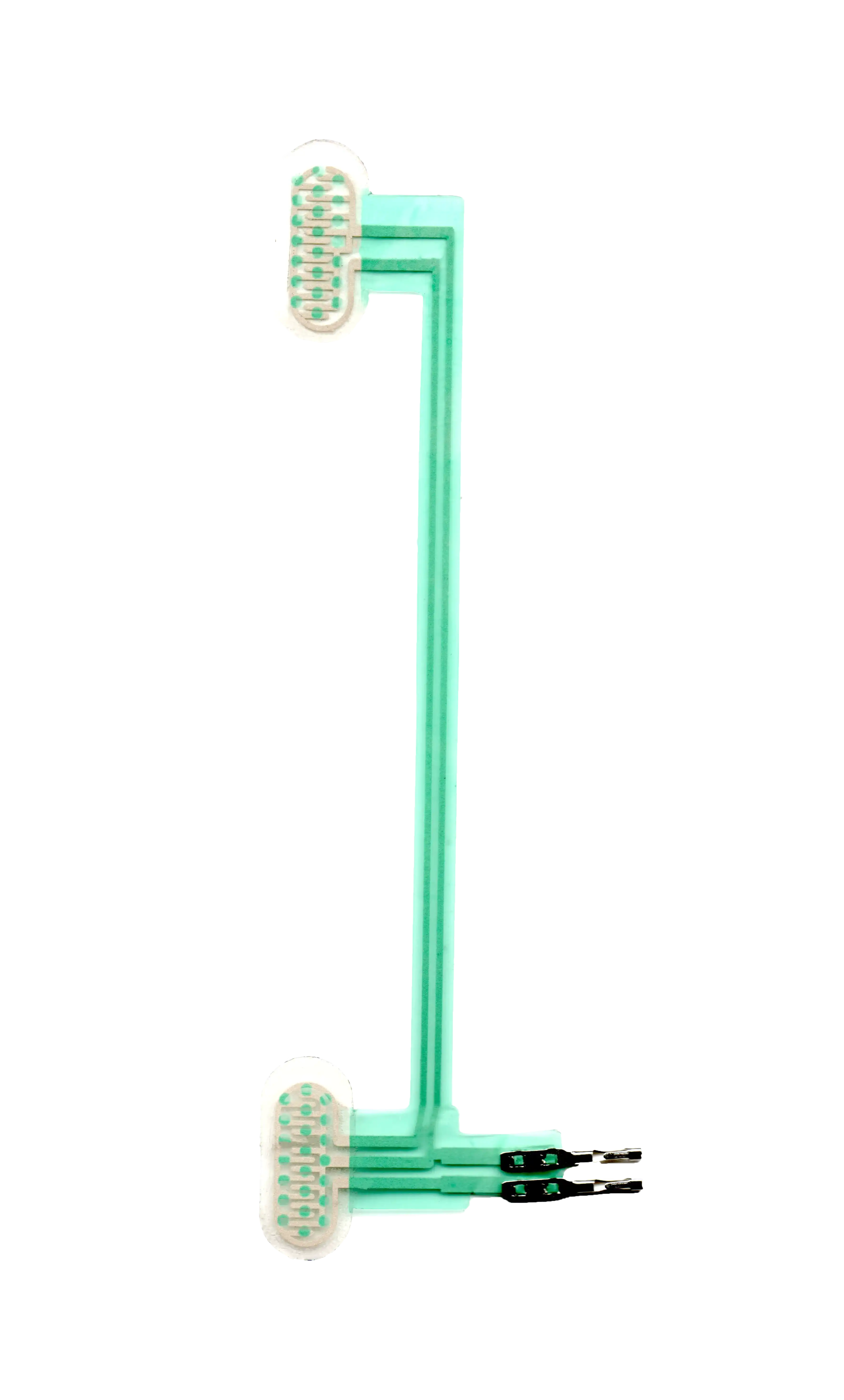
Why one resistance reading cannot release a seat sensor mat
A seat mat is loaded through upholstery, cushion foam, adhesive layers, and the seat support. The same nominal applied force can produce different pressure distributions if the platen, foam thickness, sensor location, or assembly preload changes. On a force-sensitive resistor (FSR), resistance can also move during the hold and after unloading. A contact-style membrane mat may behave as an open/closed switch rather than as an analog resistance element at all.
Consequently, a number written as “pass at 20 kΩ” is incomplete. Was it observed at the connector or at an isolated sensing zone? At what force and location? At the moment of contact or 10 seconds later? Through which excitation circuit? At what temperature, and with which foam stack? Without those answers, an incoming-inspection result cannot be reproduced across laboratories or lots.
Component inspection is not seat-state approval. The part supplier can demonstrate the released mat's response under an agreed fixture. The seat integrator must establish how that fixture corresponds to the production cushion. The OEM or system owner defines electronic thresholds, diagnostics, occupancy or reminder behavior, and finished-vehicle validation. A resistance pass does not establish occupant classification or airbag safety.
Identify the electrical output before setting an ohmic window
Use the released drawing and pinout to determine what the interface actually exposes. These are different measurement routes, not interchangeable resistance grades.
| Sensing route | What the interface exposes | Appropriate incoming check | Do not assume |
|---|---|---|---|
| 1. Contact-type membrane mat | Open/closed contacts; possibly more than one zone | Unloaded isolation and loaded contact resistance under defined force and geometry | A continuous FSR resistance-versus-force curve |
| 2. Two-terminal analog FSR mat | Resistance that generally decreases as force reaches its active region | Unloaded, loaded, held, and recovery resistance windows; optionally a controlled voltage readout | One universal force-to-resistance calibration |
| 3. Multi-zone resistive mat | Several zone leads or a defined resistive network | Zone-by-zone test with documented common pins, cross-talk conditions, and full connector mapping | That a single two-pin measurement covers the whole mat |
| 4. Mat with active interface electronics | Conditioned voltage, current, digital state, or protocol | Powered functional test at the specified electrical interface | That an ohmmeter across arbitrary pins measures the sensing element |
For route 2, resistance is a continuous variable; there is no standardized menu of seat-sensor ohmic ratings that an OEM can select independently of construction and loading. Routes 1–4 above are functional alternatives, not industry resistance sizes. If the electrical route is unknown, the incoming test is incomplete regardless of the measured number. Never attach a resistance meter to an energized vehicle controller or an unidentified powered interface.
Fix the loading conditions and observation times
A useful seat sensor loaded unloaded resistance test begins with a controlled mechanical and electrical setup, not a resistor limit. The released inspection sheet should specify all of the following:
- Test article: part number, drawing revision, connector/pin map, sensor zone, and whether the part is loose, attached to the carrier, or installed in a production-intent cushion.
- Preconditioning: storage, permitted recovery time, temperature, humidity, and whether the cushion has been compressed previously. Record the actual conditions rather than assuming a room is controlled.
- Initial preload: trim tension, foam weight, adhesive compression, and any assembly fixture bias present even when no external test load is applied.
- Applied load: force in newtons (N), force verification method, contact area and shape, compliant interface, load position, application rate, and whether the action is normal to the sensing surface.
- Observation points: initial unloaded reading, loaded reading after a fixed dwell, optional longer-hold reading, and unloaded reading after a specified recovery interval.
- Electrical measurement: connector terminals, instrument range, maximum test excitation, wiring, sample rate, and whether the test reports direct resistance or a conditioned voltage.
- Acceptance basis: released windows for each state and zone, allowable variation across repeated cycles, failure disposition, lot traceability, and responsibility for resolving borderline results.
For a first fixture study, 10 seconds of loaded dwell at 23 ± 2°C is a clear, repeatable engineering target. Include a 60-second extension when sustained-loading drift may affect the design and a 30-second post-release observation when recovery matters. These are proposed study checkpoints, not sensor-wide published requirements. A quick reading at first contact cannot substitute for a settled reading if the project accepts parts based on stable occupied-state response.
A load stated only in N is insufficient: the fixture contact geometry and installed foam determine how much of it reaches the active zone. A 20 N fixture load below is a defined example input at the actuator, not an occupant-weight equivalent. A seat-level correlation study may require a different force and different geometry.
Seat mat resistance acceptance window: an executable example
This filled-in matrix shows how to write an inspection requirement with separate states and times. All numeric limits in this table are illustrative project design assumptions for a two-terminal analog mat, not vehicle thresholds, JASPER catalog specifications, measured production capability, or limits to copy into an automotive release. The example uses a production-intent foam section, an approved compliant platen, a single identified zone, 20 ± 1 N applied at that platen, 23 ± 2°C, a controlled unpowered two-terminal measurement, and three consecutive load–release cycles.
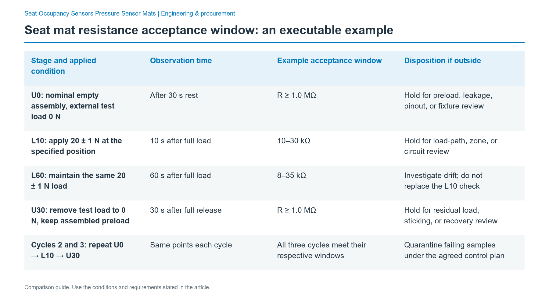
| Stage and applied condition | Observation time | Example acceptance window | Disposition if outside |
|---|---|---|---|
| U0: nominal empty assembly, external test load 0 N | After 30 s rest | R ≥ 1.0 MΩ | Hold for preload, leakage, pinout, or fixture review |
| L10: apply 20 ± 1 N at the specified position | 10 s after full load | 10–30 kΩ | Hold for load-path, zone, or circuit review |
| L60: maintain the same 20 ± 1 N load | 60 s after full load | 8–35 kΩ | Investigate drift; do not replace the L10 check |
| U30: remove test load to 0 N, keep assembled preload | 30 s after full release | R ≥ 1.0 MΩ | Hold for residual load, sticking, or recovery review |
| Cycles 2 and 3: repeat U0 → L10 → U30 | Same points each cycle | All three cycles meet their respective windows | Quarantine failing samples under the agreed control plan |
Each row represents a different question. U0 checks false activation or leakage in the specified empty condition. L10 checks the response at the chosen held load. L60 exposes additional time dependence. U30 checks return behavior; it does not require the same reading as a bare mat lying flat. The supplier and customer should replace these illustrative limits with project-specific bounds established on production-intent parts and correlated cushion builds before production acceptance.
A stronger inspection requirement also records the minimum unloaded-to-maximum loaded separation for the relevant zone and state: S = R_unloaded,min / R_loaded,max. With the example's U0 minimum of 1.0 MΩ and L10 maximum of 30 kΩ, S ≥ 33.3 at those specific fixture conditions. This ratio is a derived property of the assumed limits, not a published sensor rating. It does not replace controller-domain margin analysis or validation against real nuisance loads.
Define the measurement circuit before comparing results
A meter's stated ohms and a controller's analog-to-digital converter (ADC) reading are related only after the circuit is known. Consider a voltage divider used solely as a worked engineering calculation: excitation is 3.3 V, the mat's resistance R_sensor is the upper leg, a fixed 10 kΩ resistor R_ref is the lower leg, and V_out is measured across R_ref.
V_out = 3.3 V × 10 kΩ / (R_sensor + 10 kΩ)
| Assumed mat resistance | Calculated divider output | Meaning within this example |
|---|---|---|
| 10 kΩ | 1.650 V | Lower edge of example L10 window |
| 20 kΩ | 1.100 V | Example loaded midpoint measurement |
| 30 kΩ | 0.825 V | Upper edge of example L10 window |
| 1.0 MΩ | About 0.0327 V | Example unloaded minimum resistance |
Reversing the divider legs reverses the direction of voltage change; changing excitation or reference resistance changes every voltage value. ADC quantization, resistor tolerance, input leakage, noise, filtering, lead resistance, and sample timing further affect the observed result. The output values here are calculated, not production test measurements. An active module must instead be characterized at its specified powered interface.
For initial design screening, the team may target at least 20% headroom to the nearest customer-defined decision boundary, measured in that boundary's own signal units, at nominal installed-seat conditions. This is an illustrative project target, not a universal threshold or proof of full environmental margin. The final controller tolerance analysis must test worst-case component variation, electronics, temperature, seat geometry, legitimate empty-seat loads, and fault states. Do not infer vehicle operating thresholds from a component test illustration.
A pass/hold decision path for incoming inspection
Apply a decision sequence that preserves evidence instead of making every out-of-window result a defective sensor:
- Verify identity. Match part number, zone, drawing revision, pinout, and released test method. Wrong revision or unknown pins → hold without electrical judgment.
- Verify the fixture. Confirm cushion stack, contact area, force, position, load rate, instrument calibration status, and actual environment. Incorrect setup → correct it and restart; retain the first result.
- Measure the empty assembly. Record U0 after the specified rest. Out-of-window empty response → check assembly preload, trapped particles, shorting, leakage, and cable stress before assigning cause.
- Apply and hold the load. Record L10 and, where required, L60. No response → inspect the load path, active zone, connector continuity, and measurement configuration. Excessive time shift → separate sensing-layer drift from cushion relaxation.
- Release and recover. Record U30. Failure to return → inspect foam recovery, trapped compression, adhesive and spacer geometry, and connector strain.
- Repeat. Perform the released number of cycles, including identical placement and timing. Cycle scatter → look for fixture inconsistency, mechanical settling, intermittent connections, or lot differences.
- Decide and document. Release only when every required state and zone meets the approved limits. Otherwise record hold, re-test authorization, analysis ownership, and the eventual disposition; do not silently adjust the window to make a lot pass.
A measured failure is not, by itself, a supplier-responsibility finding. Fixture capability and seat correlation belong in the evidence chain; a demonstrated component defect and its disposition are separate decisions.
Diagnose drift, hysteresis, and misleading unloaded readings
Drift is movement of the electrical output while the specified load remains applied. Record it as an absolute change, a percentage referenced to a named time point, or a fitted trend; never quote a percent without its reference and duration. A 10-second result alone says little about a 60-second hold or long-term compression.
Hysteresis is the difference between readings at the same force on loading and unloading. A single L10 check cannot quantify it. For design validation, measure paired ramp-up and ramp-down responses with the same rate, force sequence, location, and timing; incoming inspection can retain a simpler subset when validated correlation supports it.
Repeatability is tested by applying the same condition over multiple cycles or samples. Compare the same time point after each load application, not a fresh sample's initial reading against another sample after prolonged compression. An acceptance window can be satisfied on average while individual cycles fail; release logic must say whether every cycle or a permitted statistical sample is required.
An unloaded seat is not necessarily an electrically unloaded sensing film. Upholstery tension, compressed foam, a support rib, displaced adhesive, or a pinched tail can bias the active area. That is why an empty installed cushion, a loose mat, and a bare flat sensor require separate reference conditions. Do not use an unloaded catalog value as an automatic installed-seat rejection threshold.
Inspection record: the fields that make the decision auditable
Keep the actual reading together with the state that produced it. This table is a compact inspection-record schema; all listed fields are mandatory when their test applies, rather than optional free-text comments.
| Record field | What to capture | Why it is needed |
|---|---|---|
| Identity | Part/lot/serial or sample ID, drawing and fixture revision, zone and pin pair | Links the result to a released build |
| Mechanical setup | Seat/foam revision, platen size/material, load position, force N, application rate | Reproduces the load path |
| Electrical setup | Instrument ID and calibration state, meter excitation or V_exc/R_ref, connector state |
Explains measurement differences |
| Environment | Actual °C and %RH, preconditioning, initial rest | Keeps conditions comparable |
| State readings | U0, L10, L60 if specified, U30, units and timestamps for each cycle | Preserves a complete state sequence |
| Acceptance | Revision-controlled limit for each reading, per-state result, overall disposition | Prevents retrospective limit changes |
| Exception control | Deviation ID, re-test approval, root-cause owner, lot action and closeout | Separates a hold from an approved release |
For sample approval, retain raw time traces and the corresponding actual seat configuration alongside the summary table. For routine incoming inspection, define sample size, frequency, gauge checks, and re-test rules in the agreed control plan. Neither a nominal value nor a favorable lot average replaces the stated acceptance rule.
Connect supplier inspection to the installed-seat decision
Three responsibilities should remain separate even when teams jointly define the test:
| Owner | Owns the evidence | Does not gain from a component resistance pass |
|---|---|---|
| Sensor supplier | Released construction, pinout, relevant component tests, lot traceability, and agreed failure analysis | Authorization of vehicle occupancy logic |
| Seat integrator | Fixture-to-cushion correlation, foam/trim/support variation, mounting, tail routing, and seat assembly tests | Proof that every vehicle operating scenario is covered |
| OEM/system owner | Controller readout and tolerances, detection logic, diagnostics, threshold sign-off, safety analysis, and vehicle qualification | A substitute for system-level validation |
The broader state-and-environment coverage belongs in the seat occupancy sensor testing and validation plan. This article concentrates on how an incoming resistance result can be measured and accepted reproducibly without turning it into a whole-vehicle specification.
What to send for a manufacturable seat mat specification
A drawing-controlled resistance window is useful only when the sensing construction can be built and inspected consistently. For thin pressure and contact components, JASPER can review the intended active region, printed structure, tail routing, connector, production test access, and the component evidence required by the project. See the car seat pressure sensor product page for the relevant component route; the system decision remains with the OEM.
Prepare the cushion section, foam and installation location, intended load path, selected sensing principle, output and threshold interface, connector/pinout, validation scope, prototype and annual quantities, and the exact inspection states to be agreed. To start a project review, send your drawing with those inputs. The next useful deliverable is a joint fixture drawing and revision-controlled acceptance matrix—not a free-standing resistance number.
Frequently asked questions
Can a seat occupancy sensor be accepted at one resistance value?
No. A single resistance measurement does not define whether the mat was unloaded, loaded, settled, or recovering. Specify the assembly state, fixture geometry, force, temperature, observation time, pin pair, measurement circuit, and the acceptable result for each required state. A passing component reading also cannot approve the OEM's seat-state decision logic.
What should the loaded and unloaded resistance test record?
Record an initial unloaded reading, the loaded reading at a defined hold time, and a post-release reading after a defined recovery time. For a time-sensitive FSR design, add a longer held-load checkpoint and repeated cycles. Store the actual force, location, temperature, connector pins, circuit, and per-state limits with every result; otherwise two measurements may not be comparable.
Is there a standard resistance range for every seat pressure mat?
No. A contact-switch mat, an analog FSR, a multi-zone network, and an active electronic module expose different signals. Even two analog mats can differ because the sensing area, foam, platen, preload, and readout are different. Resistance limits belong to a released product and test configuration, not to the general phrase “seat occupancy sensor.”
Why does resistance change during a constant load?
An FSR can drift under sustained force, while the seat foam and other layers can continue to settle and redistribute pressure. Both effects can move the measured output. Fix the observation time for incoming checks and use longer load holds in validation when the real application needs them. Review the sensor, cushion, and circuit independently before blaming one layer.
How should an OEM choose a resistance acceptance window?
Start with measured distributions for acceptable and problematic states in production-intent seat assemblies, then include part variation, fixture repeatability, environmental effects, electronic tolerances, and controller-domain margins. Define separate minimum and maximum limits for each applicable state and zone. A provisional table can structure prototype learning, but final production limits must be released from the project's validation evidence.
Should inspection measure ohms or ADC voltage?
Use the signal specified for that released inspection boundary. Direct ohmic measurement can be practical for an isolated passive two-terminal element, whereas the customer may classify the same element through a powered divider or conditioned circuit. State the excitation, wiring, resistor values, sample timing, and units; never compare ohms and ADC codes as though they are identical readings.
Does a passing pressure-mat test certify seat occupancy or airbag behavior?
No. Component acceptance demonstrates only the states and conditions included in the approved component method. The seat integrator and OEM must separately assess cushion variation, realistic loads, controller thresholds, diagnostic faults, occupant-related requirements, and finished-vehicle behavior. A resistance-window inspection cannot replace occupant-classification, restraint-system, or seat-belt-reminder validation.
Bring the drawing, stack and operating conditions
JASPER engineering will review the interfaces, open risks and evidence required for a production quote.