
A pressure-sensing element wins when the controller needs a raw contact or load-related signal. An occupancy function wins when another system needs a qualified state, diagnostics, and defined behavior for ambiguous inputs. Exact load measurement or complex occupant classification may require a structural, capacitive, or multi-input architecture instead of either simple option.
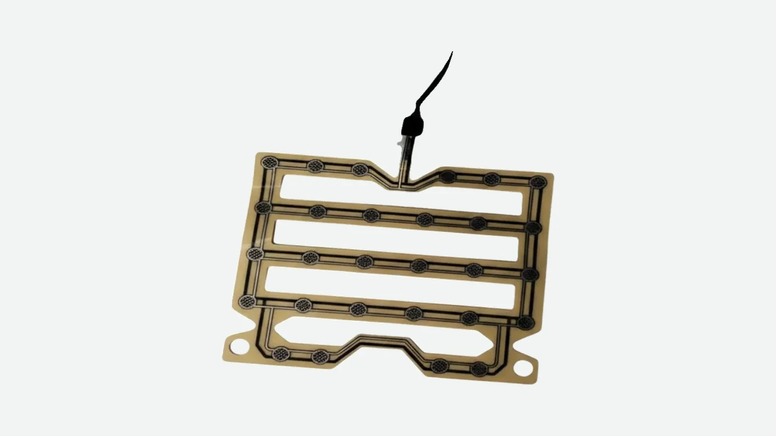
For an automotive engineer, seat pressure sensor vs occupancy sensor is not a choice between two interchangeable parts. A seat pressure sensor produces a raw response to load: a contact state, resistance, voltage, or zone pattern. An occupancy sensor or system turns one or more inputs into empty, occupied, transitional, unknown, or fault states. Choose the architecture from the required output and validation evidence. A simple switch may be sufficient for a seat-belt reminder; proportional load data, spatial classification, or restraint control requires a more complete measurement and decision chain.
JASPER's car seat pressure sensor is one flexible component route. It should be evaluated against the actual seat stack, sensing zones, circuit, connector, state logic, and test plan—not against the product label alone.
Quick Verdict: Start With the Required Output
The correct choice follows the information the next system consumes. If the downstream ECU needs one stable bit, a validated contact mat can be the cleanest answer. If it needs magnitude or zone information, an analog or multi-zone element earns its extra calibration burden. If it needs a classified occupant state, specify the complete occupant-detection function.
| Engineering question | Pressure-sensing element | Occupancy function | Selection implication |
|---|---|---|---|
| What does the term describe? | A sensing method or component | A decision the system must deliver | Method and function can exist in the same assembly |
| What is the direct output? | Contact, resistance, voltage, ADC count, or zone pattern | Empty, occupied, transitional, unknown, fault, or a richer class | Define the interface before selecting construction |
| Does it measure pressure in pascals? | Not necessarily | No; occupancy is a state | Commercial names do not define the measured quantity |
| Does it report exact occupant mass? | Not automatically | Not automatically | Absolute load needs a controlled load path and calibration model |
| Where does logic live? | Usually in an external circuit or ECU | In a controller, conditioned module, or distributed system | Assign thresholds, timing, and diagnostics explicitly |
| What dominates validation? | Load transfer, repeatability, hysteresis, drift, and circuit response | False/missed states, transition behavior, fault handling, and system integration | Bare-sensor tests cannot approve a complete occupancy function |
| When is it the wrong choice? | When the requested decision exceeds the signal's information content | When the project needs only an inexpensive raw switch or analog element | Do not buy unused complexity or demand information the sensor cannot create |
Start with the decision. Then work backward through the signal chain.
The Seat Pressure Mat Difference Is Method Versus Function
The seat pressure mat difference becomes clear when every layer is named. The mat touches the mechanical load path. The occupancy result appears only after electronics and logic qualify that signal.
Occupant, child restraint, or object
v
Trim + foam + heater + support transfer the load
v
Contact / FSR / multi-zone / structural / capacitive element
v
Contact, resistance, voltage, zone pattern, or digital message
v
Conditioning + thresholds + hysteresis + debounce + diagnostics
v
Empty / occupied / transitional / unknown / fault
v
SBR, comfort control, driver-presence, or restraint-system action
A seat occupancy sensor mat can span more than one box, depending on whether it contains only printed contacts or also includes conditioning electronics. The drawing must therefore state the system boundary. Two-wire mat is not enough; neither is smart sensor.
Force, pressure, mass, and occupancy also need separate language. NIST's SI table defines force in newtons and pressure in pascals, where one pascal equals one newton per square metre. A local force-responsive element may output ohms or volts rather than newtons. An occupancy state has no physical unit at all.
| Quantity or result | Correct unit or form | Seat-program caution |
|---|---|---|
| Force | newton (N) | Only the portion transferred through the local load path reaches the element |
| Pressure | pascal (Pa or N/m²) | Contact area and foam distribution change local pressure |
| Mass | kilogram (kg) | A cushion mat does not directly measure mass without a valid model |
| Relative load signal | resistance, conductance, voltage, or ADC count | Calibration belongs to the installed mechanics and circuit |
| Occupancy result | enumerated state or digital code | It is a decision, not a measured unit |
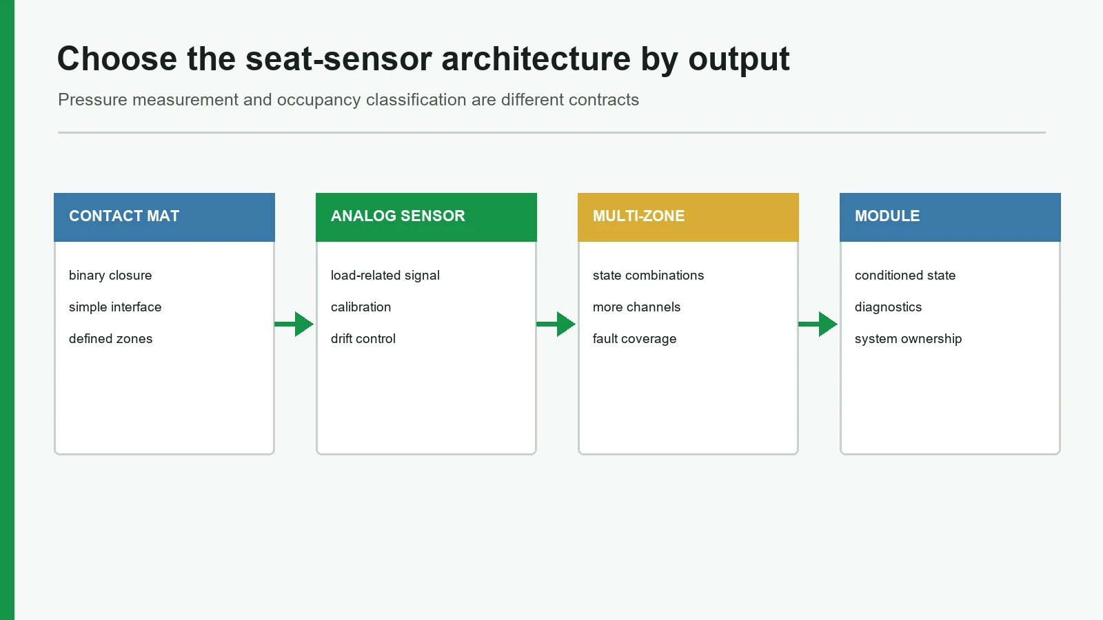
Seat Pressure Sensor vs Occupancy Sensor: Side-by-Side Outputs
The output table below is the core comparison. It treats each architecture symmetrically and includes the condition that should stop the selection.
| Architecture | Native output | Information available | Best starting use | Calibration / logic burden | Do not choose it when... |
|---|---|---|---|---|---|
| Contact pressure mat | Open/closed contact | One bit per zone | Stable occupied/empty input | Activation, release, bounce, dwell, open/short checks | The controller needs proportional load or absolute measurement |
| Analog FSR | Resistance or conditioned voltage changes with normal force | Relative magnitude and threshold margin | Adjustable threshold, relative trend, or analog zone comparison | Load interface, circuit, calibration, drift, hysteresis | A data sheet value must equal installed-seat accuracy |
| Multi-zone contact or FSR mat | Several contact or analog channels | Approximate load location or pattern | Position checks and pattern rules | More traces, pins, channels, combinations, and fault cases | No decision rule exists for each extra zone |
| Conditioned occupancy module | Qualified state or bus message | State, diagnostics, perhaps confidence/class | ECU-ready occupant detection sensor | Algorithm, diagnostics, communications, change control | The project needs only a raw low-complexity input |
| Structural load cell / strain sensor | Calibrated force-related electrical output | Controlled structural load estimate | Absolute or traceable load objective | Mounting, bridge/AFE, range, temperature compensation, uncertainty | The seat cannot provide a stable structural load path |
| Capacitive or multi-input system | Capacitance, field response, fused features, or class | Human/object discrimination or richer classes | Complex occupant classification | Electrode environment, algorithm, diagnostics, seat-specific validation | A low-cost binary switch is the only required result |
Interlink Electronics explicitly distinguishes its force-sensing resistors from load cells and strain gauges. That boundary matters. An FSR seat pressure sensor can provide useful analog information without becoming a precision structural scale.
A public benchmark is not a transferable specification
One published FSR family lists a typical 0.2-20 N sensitivity range, continuous analog resolution, +/-2% single-part repeatability, +/-6% same-batch part-to-part repeatability, and 10% average hysteresis. Force response still depends on the actuator, mechanics, and measurement electronics. These values describe that product family under its stated conditions, not a finished seat or a JASPER specification.
Where a Pressure-Sensing Element Wins
A pressure-sensing element wins when the project owns the downstream circuit and needs the raw signal more than a packaged decision. It can follow a curved cushion, place zones under selected load paths, and separate the replaceable sensing component from ECU logic.
A contact mat wins for a controlled binary requirement
Choose a contact mat when the acceptance statement can be written as contact closed under every approved occupied case and open under every approved empty/release case. The controller still needs fault behavior and timing, but it does not have to pretend that a binary contact is a low-resolution weighing device.
HDK's 2025 Seat Belt Reminder Sensor data sheet illustrates the category with a membrane-switch stack that changes from OFF to ON under a structure-defined operating load. That is one supplier's discrete architecture, not a universal activation load or contact-resistance specification.
A contact mat is not the best choice when load magnitude, pressure distribution, or adjustable bands matter. It also fails as an architecture if empty and occupied seat builds cannot be separated after foam, trim, preload, and assembly variation are included.
An analog element wins when magnitude changes the decision
Choose an analog FSR when the ECU will use threshold margin, relative load trend, or comparisons between zones. A voltage divider can convert resistance into voltage; an ADC can digitize it. Those extra counts are valuable only when the mechanical response is repeatable.
An analog element is not the best choice for traceable absolute mass merely because it returns many ADC codes. More ADC counts do not recover missing mechanical information.
Where an Occupancy-Function Specification Wins
An occupancy-function specification wins when the receiving system needs a trustworthy state and cannot interpret a raw sensor in isolation. It assigns ownership for startup, transitions, time qualification, open/short faults, implausible zone combinations, communication loss, and the fallback state.
Real vehicle designs show why this boundary matters. Audi's Self-Study Program 970133 documents one mat with eight pressure sensors where two sensors had to trigger together. The same OEM document describes another architecture using capacitive element G452, controller J706, and a LIN connection to the airbag control module. Neither product name alone reveals those state rules.
Tesla's 2026 Model Y service procedure makes a model- and market-specific distinction between a resistive-pad sensor used for seat-belt reminder and a separate Occupant Classification System on certain right-front seats. The example supports the boundary; it does not define other vehicles.
An occupancy function is not automatically the best choice. It adds software, configuration, diagnostics, communications, and change-control work. If the customer ECU already owns those tasks and needs only a qualified contact or analog input, a second decision layer can create conflicting thresholds and ambiguous fault ownership.
Mechanics and Electronics Decide More Than the Label
The automotive seat application determines how much load reaches a sensor and which failure state is acceptable. Upholstery tension, foam hardness, heater layers, adhesives, ribs, cut-outs, local support, tail routing, and connector retention all change the result.
Seat-stack change
load transfer changes
raw signal or activation point moves
threshold margin shrinks
state chatters, arrives late, or becomes wrong
downstream function acts on bad or missing information
| Failure origin | Signal-level effect | Decision-level effect | Evidence needed |
|---|---|---|---|
| Foam or trim variation | Higher/lower preload; shifted force transfer | False occupied or missed occupied | Multiple production-representative seat builds |
| Off-centre posture or object | Different zones or local pressure | Confused state or unstable transition | Approved and confusion-case matrix |
| FSR drift or hysteresis | Different rising and falling response | Threshold margin changes with dwell/history | Load/unload loops and timed dwell tests |
| Open or short circuit | Rail, zero, intermittent, or implausible signal | Unknown/fault or a dangerous default if unmanaged | Fault injection and diagnostic coverage |
| Tail or connector fretting | Intermittent resistance or lost channel | Repeated state changes or unavailable detection | Harness movement, retention, and continuity testing |
| Filter or debounce error | Excess delay or repeated transitions | Late occupied state or sticky release | Timestamped state-transition tests |
The harness row is not theoretical. NHTSA investigation PE19-009 recorded an unstable connection in an ODS sensor-mat harness that could prevent correct right-front occupant-state determination.
Hysteresis and debounce solve different problems. Texas Instruments' TIPD144 explains how two thresholds reduce repeated comparator transitions around a noisy boundary. Debounce requires a candidate state to remain valid for a specified time or sample count. Neither technique fixes overlapping steady-state data.
Empty → Occupied when signal >= T_on for D_on
Occupied → Empty when signal <= T_off for D_off
Required relationship: T_off < T_on
If approved empty and occupied cases overlap after seat variation, stop. Filtering cannot create separation. Change the sensor position, zone layout, load path, circuit, or architecture instead of hiding the overlap.
Material scope also depends on installation. In NHTSA interpretation 07-002489, material incorporated into a listed seat component and within 13 mm of its occupant-compartment-facing surface could fall within FMVSS 302 testing scope. That is an applicability review, not a product certification.
Decision Matrix: Match the Architecture to the Task
This seat load sensor comparison starts with the system task. The stop condition column prevents a familiar sourcing error: forcing a thin mat to answer a question that requires another measurement principle.
| Required task | Recommended starting architecture | Critical project input | Acceptance metric | Stop condition |
|---|---|---|---|---|
| Binary seat-belt-reminder input | Contact mat or validated analog threshold | Approved occupied, empty, object, and release cases | Correct-state rate; activation/release repeatability; fault detection | Cases overlap across representative seats |
| Adjustable load-related threshold | Analog FSR or similar element | Load interface, circuit, bands, dwell, environment | Threshold margin, hysteresis, drift, repeatability | Absolute accuracy is required without a controlled reference |
| Load-position or pattern decision | Multi-zone contact/analog mat | Zone purpose, layout, channel count, pattern rules | Zone coverage, confusion matrix, channel diagnostics | Zones add data but no decision value |
| Absolute structural load estimate | Load cell or strain-based route | Load path, range, uncertainty target, mounting | Calibration error, uncertainty, creep, repeatability | Cushion pressure is the only available load path |
| Human/object or occupant classification | Capacitive, pattern, structural, or multi-input system | Required classes, confusion cases, diagnostics, system requirements | Class confusion matrix and fault-safe behavior | One threshold must distinguish every posture and object |
| Conditioned ECU-ready state | Occupancy module | State model, bus, timing, diagnostics, fallback | State timing, communications, diagnostic coverage | Customer ECU already owns the same decision logic |
An automotive occupant detection sensor may support a reminder, comfort function, driver-presence function, or restraint system. Those uses do not share one validation burden. 49 CFR 571.208 specifies vehicle-level automatic-suppression outcomes for child-restraint/child-dummy and 5th-percentile adult-female cases; it does not mandate a pressure mat or one universal trigger weight.
When a thin flexible mat is not the best construction
A thin contact or FSR mat is the wrong starting point when the requirement calls for traceable absolute load, classifies people and objects that produce overlapping pressure patterns, depends on a structural load path that the cushion cannot control, or allocates safety diagnostics the component cannot perform. In those cases, evaluate structural sensing, capacitive fields, a conditioned module, or sensor fusion.
Prototype and Sample Approval Matrix
A sample should be approved as part of the seat and circuit, not by finger pressing a loose mat. The matrix below converts the architecture decision into observable evidence.
| Test layer | Conditions to vary | Record | Approval evidence | What failure means |
|---|---|---|---|---|
| Element | Load/unload points, dwell, contact area, repeated cycles | Contact state or raw analog curve | Repeatability, hysteresis, drift, and damage limits | Element or interface is unstable before seat integration |
| Seat stack | Foam lots, trim tension, heater layer, adhesive, support, preload | Signal margin and state | Separation across representative builds | Mechanical load path must change |
| Use cases | Approved occupants, objects, child restraints where relevant, posture, front-edge load | State, zone pattern, transition time | No missed/false states inside the approved matrix | Architecture lacks required information |
| Environment | Project temperatures, humidity, soak/dwell, recovery | Baseline, threshold margin, state recovery | Limits tied to the real specification | Materials, circuit, or calibration need revision |
| Electrical faults | Open, short, intermittent channel, supply variation, connector motion | Raw signal, diagnostic code, fallback state | Defined detection time and safe response | Fault ownership or coverage is incomplete |
| Production evidence | Dimensional checks, traceability, process settings, end-of-line test | Lot and part records | Approved control plan and PPAP evidence where required | Sample performance cannot be reproduced at production rate |
JASPER's testing and quality-control capability can be reviewed against the component-level rows; the OEM or system owner must close seat-, software-, and vehicle-level rows. The related seat occupancy sensor mat case may help frame sample questions, but an anonymized case is not a named-customer endorsement.
AIAG's PPAP overview connects production approval with engineering records, specification requirements, and consistent output during an actual production run. That is the right evidence direction. A polished prototype alone is not production approval.
Project Input Checklist and Next Step
Before requesting a design, record these inputs in one controlled brief:
- required system action and state model;
- measured quantity or raw electrical output, with units;
- approved occupied, empty, object, posture, and release cases;
- complete cushion stack, support, heater, trim, preload, and installation drawing;
- sensing zones, inactive borders, tail path, bend limits, connector, and pinout;
- contact rating or analog circuit, excitation, ADC, sample rate, filters, thresholds, hysteresis, and debounce;
- open/short/intermittent diagnostics and fallback state;
- environmental, dwell, recovery, durability, and chemical-exposure conditions;
- sample sizes, seat variants, fixtures, data format, and pass/fail rules;
- process controls, inspection traceability, change notification, and PPAP level if applicable; and
- explicit ownership for component, seat, ECU, software, and vehicle validation.
Use that brief to choose the sensor architecture before comparing samples. JASPER can be listed as one custom-component option, while structural load cells, capacitive classification, and multi-input systems remain credible alternatives when the decision matrix points elsewhere. The next step is to submit the completed architecture brief with the seat drawing and validation matrix.
Frequently Asked Questions
Is a seat pressure sensor the same as a seat occupancy sensor?
No. A seat pressure sensor describes a component or method that responds to load, while a seat occupancy sensor describes the function that decides whether the seat is empty, occupied, transitional, unknown, or faulty. A pressure-responsive element can be one input to that function.
Does a seat pressure sensor measure exact occupant weight?
Not automatically. A contact mat provides a state, and an FSR normally provides a relative load-related signal. Exact load or mass estimation requires a controlled structural load path, a suitable sensor, calibration, an uncertainty target, and validation across the complete installed system.
What is the seat pressure mat difference from an occupancy sensor mat?
The names can describe the same physical assembly, but they emphasize different boundaries. A pressure mat describes how load creates a signal. An occupancy mat describes the intended decision. The drawing must still define zones, output, activation and release conditions, electronics, diagnostics, and validation ownership.
Is a contact mat or an FSR better for occupied-and-empty detection?
A contact mat is usually simpler when the only required output is a stable binary state. An FSR is useful when the controller needs adjustable thresholds, margin, relative load trend, or zone comparison. Neither is better if approved empty and occupied cases overlap in the installed seat.
When should a seat load sensor or load cell replace a pressure mat?
Use a structural load sensor or load cell when the project needs a calibrated force estimate, controlled uncertainty, or reduced dependence on local cushion pressure. It requires a defined load path and mounting structure. A thin pressure mat remains preferable when flexibility and discrete or relative sensing are sufficient.
Can one occupant detection sensor distinguish an adult, child restraint, and bag?
It cannot be assumed. A single threshold may confuse cases that transfer similar load. Complex classification can require pressure patterns, structural load, capacitance, seat position, buckle or belt-tension inputs, diagnostics, and seat-specific software. The required class matrix should select the architecture and prove its limits.
How should hysteresis and debounce be specified for a seat sensor?
Specify separate rising and falling thresholds, then define how long or how many samples a candidate state must remain valid. Hysteresis reduces switching around a noisy boundary; debounce qualifies time. Both require measured margin across representative seats, environments, postures, dwell periods, and component variation.
Does FMVSS 208 certify a seat pressure sensor or set its trigger weight?
No. FMVSS 208 defines vehicle-level occupant-protection and automatic-suppression test outcomes. It does not certify an individual pressure mat, mandate one sensing technology, or provide a universal component trigger weight. The vehicle manufacturer and system integrator must allocate requirements and demonstrate applicable compliance.
Technical References
- Source: NIST Guide for SI force and pressure units. Accessed 2026.
- Source: Interlink FSR 400 Series technical data. Accessed 2026.
- Source: HDK seat belt reminder sensor technical data. Accessed 2026.
- Source: NHTSA investigation PE19-009 occupant detection harness. Accessed 2026.
- Source: AIAG Production Part Approval Process overview. Accessed 2026.
- Source: NIST's SI table. Accessed 2026.
- Source: Interlink Electronics. Accessed 2026.
- Source: FSR 400 Series data sheet. Accessed 2026.
- Source: Seat Belt Reminder Sensor data sheet. Accessed 2026.
- Source: Self-Study Program 970133. Accessed 2026.
- Source: NHTSA investigation PE19-009. Accessed 2026.
- Source: Texas Instruments' TIPD144. Accessed 2026.
- Source: NHTSA interpretation 07-002489. Accessed 2026.
- Source: 49 CFR 571.208. Accessed 2026.
- Source: AIAG's PPAP overview. Accessed 2026.
Choose the architecture by required output
Send the seat-system decision, load range, mechanical stack, output interface, failure behavior, and approval tests.