
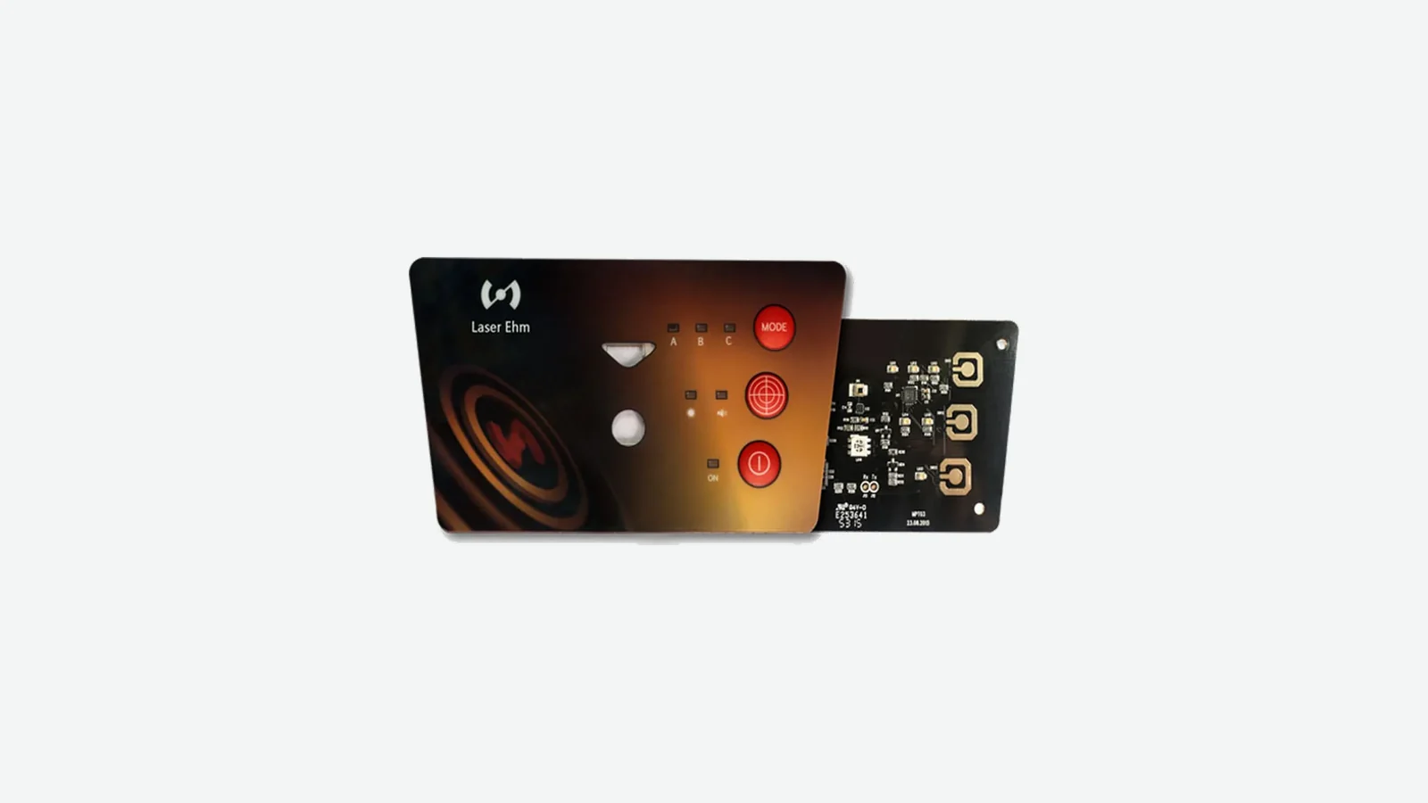
A membrane switch HMI assembly is the released physical operator-interface module that aligns a printed overlay, switch circuit, display or window, interconnect, support, sealing features, and agreed inspection evidence. It does not automatically include PLC software, controller firmware, cabinet wiring, or finished-equipment approval.
1. What Is a Membrane Switch HMI Assembly—and What Is Outside Its Boundary?
A membrane switch HMI assembly is a physical front-panel module released against one mechanical, graphic, electrical, and inspection baseline. Unlike a loose switch, it may place the membrane stack on a carrier or backplate, register a display window to a named display, route the tail to a selected connector, and include gaskets, labels, fasteners, or agreed assembly checks. JASPER's public page for membrane switch HMI assemblies describes that scope with “may” and “can” language; only the quotation, BOM, and assembly drawing make an item part of the deliverable.
The word HMI creates confusion because it can also mean a touchscreen terminal, PLC display, or software runtime. This article uses HMI only for the operator-facing physical hardware. The controller may sit behind the panel, but firmware, PLC/SCADA logic, safety logic, cabinet wiring, and complete-machine validation remain outside the default boundary. JASPER states the same distinction on its HMI assembly overview.
| Sourcing object | Typical controlled content | What it does not establish |
|---|---|---|
| Loose membrane switch products | Printed overlay, switch/spacer layers, circuit, tail, rear adhesive, optional domes or LEDs | Display position, rear support, enclosure fit, controller behavior, or machine compliance |
| Membrane switch control panel assembly | Loose-switch content plus explicitly released window/display relationship, PCB/FPC or carrier, connector, bezel/backplate, gasket, hardware, and inspection state | Unlisted customer parts, host software, system wiring, or automatic regulatory approval |
| HMI terminal or controller | Display electronics, processor, communication interface, runtime, and application software | The custom membrane overlay and enclosure interface unless specifically designed into it |
| Finished equipment | HMI module, enclosure, power, wiring, controller, software, safety functions, labels, and installation | Nothing beyond the declared conformity and validation scope |
The practical boundary rule is simple: being shown is not the same as being supplied. A display or PCB drawn for reference must be marked included, , or reference-only. Its revision, sourcing owner, replacement rule, and acceptance method must follow the same status. That one line in the BOM prevents a concept rendering from quietly becoming a purchasing obligation.
2. The Overlay-to-Controller Stack in a Membrane HMI Front Panel
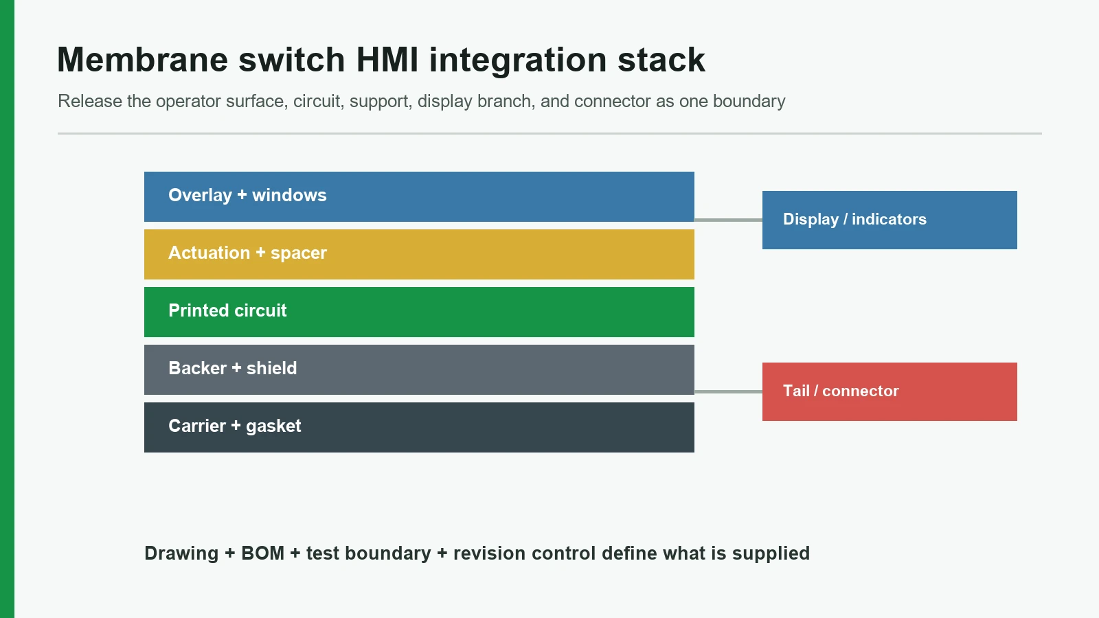
A membrane HMI front panel is not one uniform laminate. It is a stack plus two branches: the display/support branch behind the viewing aperture and the interconnect branch leading to the host electronics. Every branch needs a datum, an owner, a revision, and acceptance evidence.
Conceptual stack, operator side to equipment side:
OPERATOR
Hardcoated overlay + subsurface graphics + clear/dead-front windows Overlay adhesive / optical bond only where the released design requires it Actuation stack: embossing, dome retainer, metal dome or non-tactile spacer Circuit: printed PET, printed electronics, etched-copper FPC, or rigid PCB Backer / shield / rear mounting adhesive Bezel, carrier, or backplate + gasket and fastening features
7A. Display, indicators, and local PCB on shared datums
7B. Tail, stiffener, connector, strain relief, and test access
HOST CONTROLLER / ENCLOSURE / FINISHED-EQUIPMENT BOUNDARY
This diagram is a release map, not a universal recipe. A simple switch may stop after Layer 5. A keypad display integration can add a window without supplying the display. A larger module may include the named display and PCB but still stop at a connector whose mating half belongs to the OEM.
| Layer or interface | Functional job | Controlling input | Minimum approval evidence |
|---|---|---|---|
| Overlay and artwork | Operator labels, tactile surface, cosmetic zones, display/LED apertures | Released artwork, material/finish, color reference, key map, lit and unlit states | Approved visual master plus critical dimensions from shared datums |
| Adhesive and spacer | Bond layers and keep contacts separated until intended actuation | Named tape/adhesive, thickness, substrate, cut geometry, vent path, lamination process | BOM identity, converted-part drawing, surface preparation, representative bonded sample |
| Dome or non-tactile contact | Produce the intended closure and, when selected, tactile response | Dome part or contact geometry, actuator, support, travel limit, venting | Installed force-displacement reference and functional sample—not a loose dome alone |
| Circuit | Route key, LED, ground, and test networks | Schematic, netlist, conductor system, crossings, pinout, test points | Network test plus dimensional/visual checks appropriate to the circuit route |
| Display and window | Keep the clear aperture, black mask, active area, and indicators registered | Display drawing, active area, viewing cone, mounting datum, gap or optical-bond specification | Production-intent window/display sample under defined powered and ambient states |
| Tail and connector | Transfer signals without a crease, contact-side error, or installation load | Tail exit, keep-outs, conductor pitch, thickness, stiffener, contact side, connector model, mating part | Mated sample, pinout test, route/clearance check, insertion and service instruction |
| Bezel, backplate, and gasket | Support active keys, locate the module, and create the intended enclosure interface | Panel cutout, support lands, fastener loads, gasket path, compression design, flatness | Fit fixture or representative enclosure with the planned mounting sequence |
| Controller boundary | Define the electrical condition the supplied module can prove | Supply voltage, scan method, pull-ups, LED drive, debounce owner, diagnostic state | Interface-control document and agreed fixture result; OEM system validation remains separate |
A named material can change more than thickness. For example, 3M 7956MP uses two 0.05 mm adhesive layers around a 0.05 mm PET carrier, for a nominal 0.15 mm spacer construction. That figure describes one product, not a default HMI stack; it shows why “spacer” must resolve to a BOM item and converted geometry.
The display must be controlled with the same precision of language. A current Newhaven Display module specification, used here only as a drawing example, identifies module outline, active area, mounting features, connector, pinout, and electrical data separately. The HMI drawing should do the same. Centering a window on the module outline is not equivalent to centering it on the active image.
3. Six Integration Decisions That Control the Assembly
The six decisions below determine whether individually correct parts become one buildable HMI. They should close before tooling or production release, while artwork, circuit, display, and enclosure changes can still be reconciled without hidden rework.
3.1 Build one datum scheme and budget the complete tolerance chain
Registration must start from features shared by the finished assembly, not from whichever file a supplier opened first. A practical scheme may use the mounting face as primary datum A, a locating edge or hole pattern as datum B, and an orthogonal feature as datum C. The overlay artwork, switch centers, window, display active area, PCB, connector access, and enclosure cutout then locate from that same frame. A companion guide to front-panel HMI tolerance-stack and datum planning provides the calculation workflow.
The drawing also needs a tolerance-allocation method. A display-window margin, for example, must absorb the overlay cut, printed black mask, adhesive placement, display carrier, fastener clearance, and enclosure location—not only the die-cut window tolerance. The OEM may use a worst-case stack for a hard visual boundary or a justified statistical method for controlled processes. Either way, the method and contributors belong in the design record.
dimension the functional relationship—key legend to contact center, clear aperture to active image, tail to mating connector—not a chain of convenient intermediate edges.
3.2 Select overlay film, print system, and mounting adhesive as one surface system
“PET or polycarbonate” is not a complete overlay specification. Finish, hardcoat, primer, ink family, gauge, forming or embossing, clear-window quality, UV exposure, cleaners, and cosmetic criteria all matter. MacDermid's Autotex technical data describes textured hardcoated PET in 150, 200, and 280 µm product grades with different primers for solvent and UV-cured inks. Covestro's polycarbonate and PC/PBT films also branch into grade-specific surface, forming, weathering, optical, and flammability options. Neither catalog supports a universal material winner.
Mounting adhesive must then match the real enclosure surface. 3M's October 2023 data lists nominal 0.06 mm and 0.13 mm 200MP transfer-tape options. The two calipers serve different stack and surface conditions; neither selects an adhesive for powder coat, molded texture, residual release agent, cleaning fluid, or a curved bezel. Bond coupons should use the production substrate, preparation, pressure, dwell, and exposure sequence. A deeper guide to industrial adhesive selection for HMI assemblies extends that substrate-and-exposure decision without turning a tape family into a default specification.
approve the overlay, ink, adhesive, substrate, and cleaning process as a system; a tape trade name alone is not a bond specification.
3.3 Choose the circuit route from density, components, termination, and flex duty
The circuit technology should follow the electrical and mechanical problem. Cost shorthand such as “PET is cheap” or “FPC is reliable” hides the variables that actually determine the result. Use the comparison of PCB vs FPC integration in HMI front-panel assemblies when the sourcing decision turns on rigid-board support, copper-flex routing, components, or connector density.
| Circuit route | Choose it when | Watch closely | Release documents |
|---|---|---|---|
| Screen-printed silver on PET | The key matrix is modest, the tail is installation-flex only, and the design suits printed conductors and dielectric crossings | Finished trace resistance, cure control, silver migration risk under the specified environment, connector termination, and unsupported folds | Artwork, netlist, ink/dielectric system, printed thickness/process controls, tail drawing, electrical limits, test method |
| Printed electronics on flexible substrate | Sensors, additive conductors, or another printed structure require a documented printed-electronics route | Do not mix design guidance with performance acceptance | Invoke the applicable IPC-2292A design and IPC-6902 performance requirements in procurement documents |
| Etched-copper FPC | Routing density, plated features, fine connector pitch, soldered parts, or defined flex-board construction justifies copper flex | Installation flex versus continuous flex, bend region, coverlay, stiffener, plated features, and connector strain | Stack-up, IPC-2223 design basis, IPC-6013E class/use, fabrication drawing, impedance/current rules where relevant, test coupon and acceptance plan |
| Rigid PCB or PCB-backed switch | The HMI needs structural support, dense SMT components, rigid connectors, or a local controller board | Board-to-overlay height, dome support, fastener load, LED/display alignment, service access, and assembly cleanliness | PCB fabrication/assembly data, mechanical model, BOM, firmware/interface boundary, test fixture, programmed-state definition |
Henkel's LOCTITE EDAG PF 410 data sheet illustrates the evidence boundary: it publishes typical ink sheet resistance at a stated thickness and a drying cycle, but it cannot predict a finished key-matrix loop. Trace length and width, printed/cured thickness, crossings, contacts, tail termination, and measurement force still govern the released circuit value.
name the circuit family and its governing design/performance documents. “Flex tail” does not distinguish a printed PET circuit from an etched-copper FPC.
3.4 Treat keypad display integration as an optical and mechanical branch
Keypad display integration starts with four different shapes: module outline, active image, visible aperture, and printed black mask. Add viewing angle, display-to-window gap, dust control, light blocking, connector clearance, and service strategy. If a touch sensor is present, its stack, controller, grounding, and cover-lens requirements form another branch. An HMI display-window alignment and parallax review addresses the geometry and viewing-angle branch in more detail.
An air-gap design may simplify display replacement and isolate the overlay from module stress, but it needs controlled spacing, internal cleanliness, and reflection management. Full optical bonding can remove an air interface, yet it adds adhesive selection, clean handling, lamination, bubble control, rework risk, and display-specific stress concerns. The current 3M CEF08XX/OCA 821XX guide describes grade/thickness selection and controlled roller, vacuum, and autoclave processing; it labels the data typical and the cited family general-purpose/non-touch. That is a process example, not permission to specify OCA generically.
identify the bonding architecture, named display revision, visual states, cleanliness class or defect criteria, and replacement policy before the window geometry is frozen.
3.5 Design the tail and connector as a mated system
A tail is not complete until the mating connector and installed route are known. The release package needs conductor pitch and width, tail substrate thickness, exposed length, contact side, plating or ink contact, stiffener material/thickness, insertion orientation, latch operation, bend keep-out, strain relief, clearance, and service cycles.
The Molex 70430 specification is a useful boundary example because it permits silver-ink conductors on PET only within the dimensions defined for that 2.54 mm-pitch family. Molex's Easy-On FPC/FFC application specification separately instructs users to insert the flex straight and route it without loading the stiffener or connector. Neither document is a generic tail rule. The selected connector drawing wins.
For project preparation, JASPER's tail and connector design guide can organize the input list, but the OEM and connector manufacturer documents control electrical and mechanical acceptance.
approve a mated, installed tail route. A continuity result on a flat bench cannot prove connector access or strain after enclosure assembly.
3.6 Close support, sealing, and controller ownership together
The backplate or carrier must support active keys without blocking required vent paths or loading the display. Openings, PCB pockets, fasteners, and gasket compression can change the mounted key response even when the loose switch sample was acceptable. JASPER's lamination and HMI assembly page lists alignment, pressure, contamination, trapped air, exposed adhesive, tails, connectors, and protective handling as process control points; it does not publish one universal build limit.
Sealing is likewise an assembly property. IEC 60529 classifies protection provided by enclosures. An overlay, gasket, or rear adhesive may contribute to the boundary, but none confers an IP code on its own. The evaluated configuration must identify the bezel, window, perimeter land, gasket, fasteners, seams, tail exit, connector path, enclosure, mounting state, and exposure direction.
Finally, write an interface-control document for the controller handoff. At minimum, define connector and pinout, matrix topology, voltage/current limits, pull-ups, LED polarity/drive, grounding/shield termination, scan and debounce owner, power-on state, diagnostic access, and fixture behavior. Firmware can be inside the commercial scope only when the quotation and release package say so.
the physical support, sealing specimen, and electrical handoff must describe the same production-intent configuration.
4. Failure Chains: Why a Correct Part Can Fail as an Assembly
Assembly failures often begin at an interface that no single component drawing owns. The table below is a design-risk map, not a field-failure dataset: it connects plausible causes to observable symptoms so the drawing and approval plan can intercept them.
| Root condition | Local effect | Assembly symptom | Prevention or detection control |
|---|---|---|---|
| Overlay, window, display carrier, and enclosure use independent datums | Individual position errors accumulate in different directions | Uneven visible border, legend-to-key offset, LED halo, or aperture interference | Shared A/B/C datum scheme, explicit tolerance budget, production-intent alignment fixture |
| Dome or non-tactile contact sits beside an unsupported display/PCB opening | Local structure deflects instead of transferring the intended load | Edge keys feel different, closure point shifts, or release becomes inconsistent after mounting | Continuous support lands, controlled vent path, installed force/functional review at center and edge keys |
| Mounting adhesive is chosen from the overlay material but not the enclosure surface | Incomplete wet-out or chemical incompatibility develops at the bond line | Corner lift, trapped air, cosmetic read-through, or an unintended liquid path | Production-substrate coupons, defined cleaning/preparation, lamination pressure, dwell, and exposure sequence |
| Tail route crosses a sharp edge or loads the connector stiffener | Conductor, termination, or connector sees concentrated strain | Intermittent signal, damaged latch, difficult installation, or failure after service | Bend keep-out, edge radius/clearance, strain relief, representative mating and service-cycle check |
| A display is substituted by diagonal size or marketing name | Active area, outline, connector, pinout, thickness, or optical state changes | Window no longer frames the image, cable does not reach, or powered-state inspection becomes invalid | Named manufacturer part/revision, controlled drawing, approved alternate process, revalidation trigger |
| Gasket, fastener torque, carrier, or enclosure flatness changes | Compression and panel load redistribute through the stack | Key feel shifts, display stress appears, or the evaluated sealing boundary changes | Assembly sequence, fastener/load control, gasket specification, flatness limits, mounted-sample approval |
| Electrical continuity is checked only on the loose circuit | Fit, support, display, tail, and connector defects remain invisible | The part passes final electrical test but cannot be installed or behaves differently when mounted | Combined network, visual, dimensional, fit, mounted-actuation, and connector-access checks |
| Packaging is designed after cosmetic approval | Protective film, tray, or tail restraint contacts a critical surface or applies load | Scratches, imprint, bent tail, or disturbed gasket arrives at incoming inspection | Package state included in first-article approval and change control |
The corresponding control plan should place checks before later layers hide the evidence. JASPER's public inspection and traceability page describes project-defined links among materials, lots, process steps, inspection, deviations, labeling, packaging, and shipment; it does not claim that every characteristic receives 100% inspection.
JASPER also publishes an anonymous HMI front-panel assembly example. It is useful for seeing a real component arrangement, but the page does not disclose a customer, machine, volume, or verified field result. Photographs cannot establish ingress, EMC, lifetime, compliance, or finished-equipment performance.
5. Release Process: From Layout to a Production-Intent Assembly
A reliable release process turns separate artwork, electrical, display, and enclosure files into one controlled baseline. Five gates are enough when each gate has an owner, output, and rule for reopening the decision.
| Gate | Work to close | Controlled output | Reopen when |
|---|---|---|---|
| 1. Map the operator interface | Confirm key map, labels, languages, display and indicator states, glove/cleaning conditions, cosmetic zones, and service concept | Approved requirements sheet, artwork source, named owners, open-issue list | Operator workflow, language, display, or enclosure changes |
| 2. Release the physical and electrical stack | Reconcile shared datums, overlay/ink, adhesive/spacer, dome/contact, circuit, display/window, support, gasket, tail, connector, pinout, and host interface | Cross-section, assembly drawing, BOM status, schematic/netlist, interface-control document, preliminary control plan | A layer, part, supplier, mounting feature, or electrical interface changes |
| 3. Build a production-intent sample | Use intended materials, converted geometry, rear support, display/PCB state, connector route, fastener/gasket condition, and planned packaging | Identified sample with deviation list; representative fit fixture or enclosure | Sample construction differs from the planned repeat build |
| 4. Approve the assembly evidence | Review appearance, dimensions, window/lighting, installed key behavior, circuit/pinout, connector access, fit, protection, reports, and unresolved system tests | Signed approval record, golden references where appropriate, acceptance limits and measurement methods | Evidence is ambiguous, subjective criteria lack a reference, or the OEM system test finds an interface issue |
| 5. Freeze production and control change | Release active files, inspection points, test fixture/software state, labeling, packaging, deviation process, alternate-part rules, and requalification triggers | Production baseline, revision hierarchy, traceability plan, change-notification workflow | Any approved material, artwork, circuit, component, tool, process, supplier, inspection, software boundary, or package changes |
Three details keep this workflow honest.
First, the revision hierarchy must say which file wins when artwork, 2D drawing, 3D model, schematic, BOM, and approved sample disagree. “Latest file” is not a hierarchy. Second, a production-intent sample must record deviations; otherwise a hand-built workaround can become an invisible requirement. Third, subjective properties—color, texture, key feel, light uniformity, acceptable particles—need a reference, viewing/actuation condition, and named approval owner.
JASPER's engineering change control page treats artwork, circuit, material, adhesive, ink, dome, LED, connector, PCB, tooling, process, supplier, inspection, and packaging as potential changes. That is the correct breadth for an integrated HMI: a substitution can preserve one component's form and still invalidate the assembly evidence.
6. Test Matrix: Component, HMI Subassembly, and Finished Equipment
Testing must prove a named characteristic on a named specimen under named conditions. A membrane switch HMI assembly can pass its drawing-controlled checks while the finished machine still requires ingress, EMC, safety, software, and application validation. JASPER's testing and validation planning page makes that boundary explicit and does not publish a universal test package, sample size, method, or acceptance limit.
| Risk or characteristic | Component evidence | Supplied HMI subassembly evidence | Finished-equipment responsibility |
|---|---|---|---|
| Artwork, registration, and cosmetics | Film/print identity, artwork revision, converted dimensions, visual reference | Key/legend, window/active-area, LED/icon, overlay/bezel, and label registration from common datums | Readability in installed lighting, operator workflow, language/safety-label approval |
| Circuit and pinout | Net continuity/isolation as specified, trace/contact inspection, tail dimensions | Mated connector, complete pin map, actuated states, LED or local PCB outputs at the defined interface | Controller scan, debounce, diagnostics, fault handling, wiring, and functional safety |
| Key response and cycling | Named dome/contact data and project-defined measurements | Mounted force/closure/release reference at representative key locations; cycling on the production-intent stack when required | Operator ergonomics, glove/tool interaction, misuse loads, required service life in the real duty cycle |
| Display, window, and lighting | Display/module data; overlay transmission/color sample; LED/light-guide data | Powered visual inspection at defined ambient, angle, content, voltage, warm-up, and cosmetic criteria | UI content, luminance/readability requirement, thermal state, host dimming, alarms, and system power modes |
| Adhesive and environmental exposure | Named material data plus coupons on the actual substrate and preparation | Post-exposure bond, appearance, key, circuit, window, and fit checks on the agreed assembly specimen | Exposure from enclosure seams, internal heat, cleaning process, mounting stress, and real maintenance sequence |
| Ingress boundary | Material/gasket data can screen options but cannot assign an IP code | Only the exact tested panel/enclosure boundary can support its stated result | Final enclosure, fasteners, seams, ports, tail/connector path, installation, damage, and certification claim |
| ESD, EMC, and shielding | Ground/shield continuity or material checks as specified | Interface-level ground path and fixture checks; pre-compliance only when scope says so | Equipment-level discharge, radiated/conducted immunity and emissions, performance criteria, safety response |
| Vibration and shock | Part retention and material data | Mounted module test only under an agreed profile, axes, fixture, powered state, monitoring, and acceptance plan | Equipment installation, cabinet resonance, harness loads, transport state, and application-specific qualification |
| Regulatory or industry compliance | Declarations or recognition apply only to the named material/component and scope | Contract records for supplied parts and processes | Finished medical electrical equipment, vehicle component/system, marine equipment, machinery, and market approval |
Electrical test is deliberately narrow. IPC-9257 says flexible printed-electronics testing verifies whether conductive networks match the electrical design, while dimensions, geometry, registration, holes, and assembly suitability need other checks. That is why “100% continuity tested” cannot stand in for fit, window alignment, mounted key response, or connector access.
initial life benchmark for RFQ drafting
PB-DM-320/5M — initial upstream benchmark; replace or reconfirm before release. Snaptron F08320 is an 8.50 mm metal dome for which the supplier lists a typical actuation force of 320 gf ±30 gf and a rating of up to 5,000,000 cycles. Within the same-diameter 260/320/400 gf choices in the supplier table, 320 gf is the middle-force option; the five-million-cycle figure supplies a mid-to-upper starting point for an RFQ rather than an industry-mandated acceptance limit.
Those figures belong to the loose dome and Snaptron's stated test setup. They are a supplier-data reference, a finished-HMI lifetime, or evidence that F08320 is in the quoted BOM. If the benchmark remains in a project specification, validate the released overlay, retainer, vent path, actuator, support, load, rate, electrical conditions, environment, specimen quantity, monitoring, and failure criteria. ASTM F1578-24 can govern contact-closure cycling, but it does not select those project values.
Current references and their proper boundaries
| Reference | Appropriate use in an HMI plan | What it does not prove |
|---|---|---|
| ASTM F1578-24 | Active method for contact-closure cycling to a predetermined count, optionally under specified voltage/current | It does not choose the cycle count, actuator, rate, load, environment, sample size, measurements, or pass/fail limits |
| IEC 60068-2-14:2023, IEC 60068-2-78:2025, IEC 60068-2-6, IEC 60068-2-64, IEC 60068-2-27 | Methods for temperature change, damp heat, sinusoidal/random vibration, and shock when the project selects severities and criteria | They do not make one generic “industrial” environmental profile or define the HMI's acceptance limits |
| IEC 60529 | Classify protection provided by the declared electrical-equipment enclosure configuration | It does not rate a loose switch, adhesive strip, gasket, or window by association |
| IEC 61000-4-2:2025 | Equipment ESD immunity method with project/product-standard test levels and performance criteria | It is not a component-handling ESD test and does not prove complete EMC compliance |
| IPC-2223 / IPC-6013E | Design and qualification/performance route for etched-copper flexible/rigid-flex boards when invoked | It does not automatically govern screen-printed PET circuitry or the whole HMI assembly |
| ISO 16750-3:2023, ISO 20653:2023, ISO 10605:2023 | Automotive program examples for mechanical loads, vehicle enclosure IP, and ESD | Naming the standards does not establish compliance; mounting location, class, severity, and OEM program still control |
| IEC 60601-1 and IEC 60601-1-2 | Finished medical electrical equipment/system safety, essential performance, and EMC context | They do not certify a purchased membrane switch or transfer finished-device approval to its supplier |
most legacy membrane-switch F-series methods cited by older supplier guides were withdrawn in 2023–2024, often without replacement. A current drawing should not call them active by habit. Force-displacement, circuit resistance, chemical exposure, silver migration, hosedown, or other useful measurements can still be specified through a project-defined procedure or an applicable current IEC, IPC, ISO, customer, or product standard.
Every test line in the approval plan should therefore state: characteristic; specimen and revision; mounting/fixture; preconditioning; method and severity; powered state; functional monitoring; sample stage and quantity; measurement equipment; acceptance limit; record format; owner; and whether the specimen remains fit for use. Without those fields, a test name is only a heading.
Supplier-qualification evidence needs the same precision. A certificate identifies the legal entity, manufacturing site, standard, certification body, scope, issue date, and expiry date. JASPER maintains ISO 9001, ISO 13485, IATF 16949, and ISO 14001 certifications; the applicable scope is checked against the buyer's project requirements. Customer references are used only when the customer has authorized a non-confidential engineering result and its stated boundary.
7. When a Complete Membrane Switch Control Panel Assembly Is Not the Best Choice
A complete membrane switch control panel assembly is not automatically the lowest-risk sourcing boundary. Integration transfers interface work to one released module, but it also couples revisions, inventory, rework, service, and supplier ownership. Keep parts separate—or select another input technology—when that separation serves the product architecture.
| Project condition | Better boundary or technology | Why the full membrane HMI module may be wrong |
|---|---|---|
| The OEM already has a capable, validated panel-assembly cell | Buy the released switch, display, gasket, and carrier separately | The OEM can own alignment, late configuration, repair, and test without paying to duplicate an established process |
| One front panel must support several displays or controller revisions | Keep the display/controller on a serviceable internal carrier | A fully bonded module turns an electronics substitution into an overlay, optical, mechanical, and inventory change |
| The display is field-replaceable or has a shorter sourcing horizon than the printed front | Use an air-gap/window architecture with replaceable rear electronics | Full optical or structural bonding can increase rework scope and make service destructive |
| The interface is screen-led and physical tactile keys are unnecessary | Consider a capacitive touch HMI or standard display terminal | A membrane key matrix adds parts and artwork constraints without providing a needed operator benefit |
| Operators need tall molded keys, long travel, or strong finger location | Consider a silicone keypad or discrete mechanical controls | A thin membrane stack may not deliver the required geometry or travel |
| The enclosure is still changing rapidly | Prototype separate parts and delay integrated tooling/release | Shared datums, window margin, gasket path, support lands, and tail route are not stable enough to freeze |
| System approval requires a specific certified terminal or safety control | Keep that approved unit intact and treat the custom front as a separate mechanical interface | Integration must not obscure the certified product boundary or create unassessed modifications |
For industrial control panels, the deciding question is not whether an integrated front looks cleaner. It is whether the operator input, display, rear electronics, enclosure, service strategy, and validation cadence share a stable revision boundary. If they change on different schedules, modularity can be the more controlled design.
8. Drawing and Sample-Approval Checklist
A quote-ready package does not need every production detail, but it must expose the interfaces that can change construction, tooling, test, or responsibility. Use the HMI panel assembly design checklist to keep the file set together. Send the HMI layout, circuit data, and enclosure drawing as one review package; handling them as separate requests hides the tolerance and ownership chain.
Mechanical and assembly inputs
- [ ] Dimensioned panel drawing plus STEP/DXF/PDF data; identify the controlling file and revision.
- [ ] Primary, secondary, and tertiary datums shared by artwork, switch, display, PCB/carrier, and enclosure.
- [ ] Panel cutout, bezel/backplate, support lands, fasteners, bosses, flatness, rear clearance, and installation direction.
- [ ] Cross-section through keys, display/window, perimeter adhesive, gasket, tail exit, and any local step or pocket.
- [ ] Production-intent mating enclosure or a controlled fit fixture.
Artwork and operator inputs
- [ ] Vector artwork, key map, dead zones, display/LED apertures, embossing, cosmetic zones, and language versions.
- [ ] Color/texture references, acceptable viewing conditions, lit/unlit states, and protective-film requirements.
- [ ] Glove use, intended actuator or finger interaction, cleaning procedure, and service access.
Electrical, display, and connector inputs
- [ ] Schematic/netlist, matrix, pinout, voltage/current limits, grounding/shield strategy, LEDs, test points, and diagnostic state.
- [ ] Named display manufacturer part/revision, module drawing, active area, connector, pinout, viewing and powered inspection states.
- [ ] Tail exit and route, conductor/contact side, pitch, thickness, exposed length, stiffener, mating connector, latch access, and bend keep-outs.
- [ ] Controller, firmware, scan, debounce, communications, and fixture ownership at the commercial handoff.
Materials and environment
- [ ] Enclosure material, coating, texture, surface preparation, adhesive land, restricted substances, and approved alternates.
- [ ] Operating/storage environment, cleaners and concentrations, UV, humidity/condensation, liquid direction, vibration/shock, ESD/EMC, and transport state.
- [ ] Application-specific standards or customer specifications, including the required revision and clause where practical.
Supply, evidence, and change control
- [ ] Mark each display, PCB, connector, gasket, hardware item, label, fixture, and customer part as included, , or reference-only.
- [ ] Define prototype/pilot intent, forecast, documentation, traceability, labeling, packaging, approved-sample control, and deviation process.
- [ ] For each critical characteristic, state specimen, method, condition, sample stage/quantity, limit, record, and approval owner.
- [ ] Define material/part substitutions, notification, alternate approval, implementation lot, and requalification triggers.
Before approving the sample
- [ ] Confirm that the sample represents the planned repeat-build materials, geometry, support, display/PCB state, tail/connector route, gasket/fasteners, and packaging.
- [ ] List every deviation and decide whether it must close before approval.
- [ ] Test representative center, edge, corner, and opening-adjacent keys in the mounted state.
- [ ] Inspect the display/window and lighting at the specified content, voltage, ambient, angle, and warm-up condition.
- [ ] Verify connector access, mating, pinout, tail clearance, service action, and protected shipping state.
- [ ] Record the system-level tests that remain with the OEM; do not convert an assembly approval into a finished-equipment claim.
JASPER's engineering and DFM review page can be used to organize the first exchange. The released contract and customer specifications, not the checklist alone, determine the final deliverable.
9. Frequently Asked Questions
What is included in a membrane switch HMI assembly?
A membrane switch HMI assembly includes only the physical interface items released in its quotation, BOM, and drawings. It may combine the overlay, switch circuit, display or window, PCB/FPC, tail, connector, support, gasket, hardware, labels, and agreed checks. JASPER's public product scope does not claim that every project includes every item.
Is a membrane switch HMI assembly the same as an HMI touchscreen?
No. A membrane switch HMI assembly is a custom physical front-panel module; an HMI touchscreen often means a display terminal with processor, communications, runtime, and application software. A physical module can include a display or touch sensor, but PLC/SCADA logic, controller firmware, cabinet wiring, and finished-machine validation stay outside unless the released scope assigns them.
How should a keypad and display be aligned?
Align the key centers, visible aperture, printed black mask, display active area, display carrier, and enclosure from shared datums. Do not center the window from the display's outside dimensions alone. A module specification typically controls outline, active area, connector, pinout, and mounting features as separate quantities; the HMI drawing should preserve those distinctions.
Should the circuit use printed PET, etched-copper FPC, or a rigid PCB?
Choose from routing density, components, connector, flex duty, support, electrical limits, and procurement standard—not a universal ranking. Printed electronics can use IPC-2292A/IPC-6902 when invoked; etched-copper flex uses the IPC-2223/IPC-6013 route; a rigid PCB suits dense components and structural mounting. The drawing must name the selected route and acceptance basis.
Does a membrane switch make the finished panel IP65 or IP67?
No. IEC 60529 classifies protection provided by the evaluated enclosure. The overlay, window, adhesive, gasket, bezel, fasteners, seams, tail exit, connector path, enclosure, mounting state, and exposure direction can all affect the result. Test evidence applies only to the declared specimen and configuration, not to a loose membrane switch by association.
What should be tested before production release?
Test the risks defined by the drawing and approval plan: appearance, critical dimensions, registration, circuit/pinout, installed key behavior, display/lighting state, connector access, fit, packaging, and selected environmental exposures. Use ASTM F1578-24 when contact-closure cycling is required, but define the cycle count, actuator, load, specimen, monitoring, quantity, and limits for the project.
Who owns controller software, EMC, safety, and regulatory approval?
The released responsibility matrix decides, but these items normally remain with the OEM or system integrator. Assembly-level continuity or visual inspection does not prove equipment ESD/EMC, functional safety, medical electrical compliance, or market approval. IEC 61000-4-2:2025 and IEC 60601-1 illustrate equipment/system-level boundaries rather than component certifications.
What files are needed to quote a membrane switch control panel assembly?
10. What to Send for an Engineering Review
Send the HMI layout, circuit data, and enclosure drawing. Include the artwork/key map, display or window specification, PCB/FPC or controller interface, tail and mating connector, bezel/backplate, gasket and mounting datums, operating environment, approval evidence, and change-control expectations. Early files can be incomplete; the useful outcome is a named open-issue list, not silent assumptions.
JASPER can review the physical module against the project scope. A complete assembly is not the correct boundary when the OEM has stronger in-house integration, needs field-replaceable electronics, or is still changing the enclosure. Public component and standards sources in this article support engineering decisions; they do not establish JASPER-specific materials, tolerances, test results, certifications, lifetime, ingress rating, lead time, or finished-equipment approval.
Technical References
- Source: 3M 7956MP. Accessed 2026.
- Source: Newhaven Display module specification. Accessed 2026.
- Source: Autotex technical data. Accessed 2026.
- Source: Makrofol/Bayfol selector. Accessed 2026.
- Source: 3M's October 2023 data. Accessed 2026.
- Source: IPC-2292A design. Accessed 2026.
- Source: IPC-6902 performance. Accessed 2026.
- Source: LOCTITE EDAG PF 410 data sheet. Accessed 2026.
- Source: 3M CEF08XX/OCA 821XX guide. Accessed 2026.
- Source: Molex 70430 specification. Accessed 2026.
- Source: Easy-On FPC/FFC application specification. Accessed 2026.
- Source: IEC 60529. Accessed 2026.
- Source: IPC-9257. Accessed 2026.
- Source: Snaptron F08320. Accessed 2026.
- Source: Snaptron's stated test setup. Accessed 2026.
- Source: ASTM F1578-24. Accessed 2026.
- Source: IEC 60068-2-14:2023. Accessed 2026.
- Source: IEC 60068-2-78:2025. Accessed 2026.
- Source: IEC 60068-2-6. Accessed 2026.
- Source: IEC 60068-2-64. Accessed 2026.
- Source: IEC 60068-2-27. Accessed 2026.
- Source: IEC 61000-4-2:2025. Accessed 2026.
- Source: IPC-2223 / IPC-6013E. Accessed 2026.
- Source: ISO 16750-3:2023. Accessed 2026.
- Source: ISO 20653:2023. Accessed 2026.
- Source: ISO 10605:2023. Accessed 2026.
- Source: IEC 60601-1. Accessed 2026.
- Source: IEC 60601-1-2. Accessed 2026.
Review the complete HMI assembly before design release
Send the front-panel drawing, stack, display, circuit, connector, enclosure, service conditions, and acceptance plan for review.