
HMI display window alignment passes only when the clear aperture leaves the required LCD active area visible from every approved operator eye position, across the released translation, rotation, stack-height, print, adhesive, and gasket variation. This guide gives OEM mechanical, HMI, quality, and sourcing teams a way to define the drawing entities, calculate layered parallax, budget each window edge, and verify the assembled unit. The boundary matters: an LCD data-sheet viewing angle describes electro-optical performance under stated conditions; it does not prove that a physical bezel or printed mask will avoid clipping. Use both a geometry calculation and a final-stack viewing-zone test.
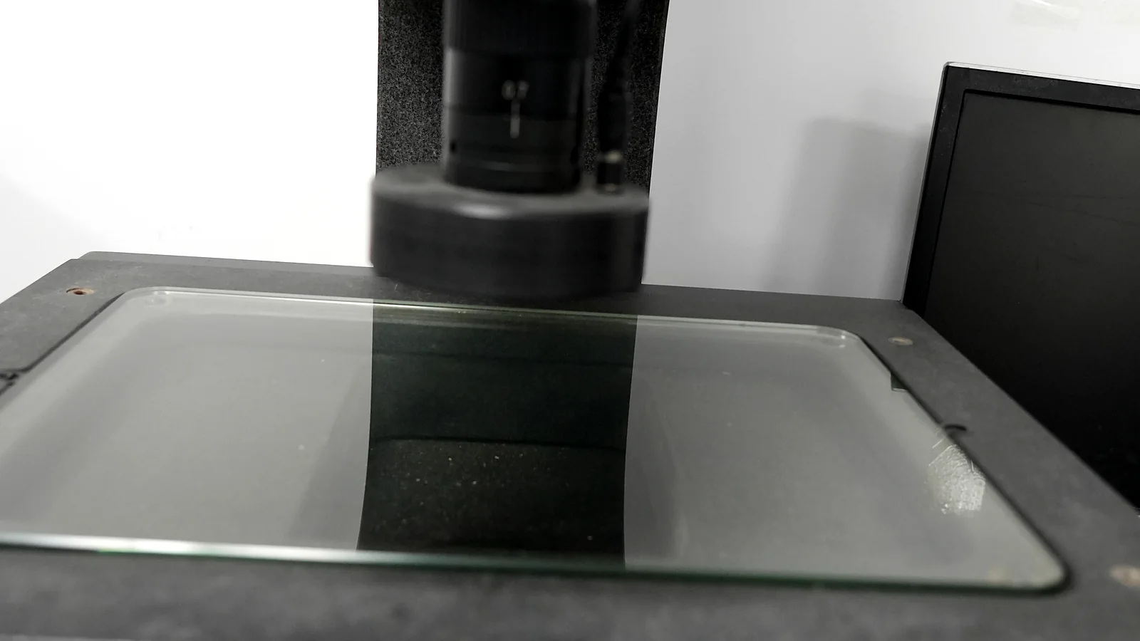
What HMI Display Window Alignment Actually Controls
HMI display window alignment controls the relationship between the visible pixel boundary and every physical edge that can hide it. Here, “display window” means the clear aperture or printed-mask opening in a front panel, overlay, or cover lens—not a software pop-up window. A review of display-window HMI assemblies should begin with source drawings for the display, front construction, carrier, and enclosure.
The drawing terms cannot be collapsed into one “screen size.” Suppliers also use viewing area differently, so each project needs its own glossary.
| Drawing entity | Practical definition | Why it must stay separate |
|---|---|---|
| LCD/TFT active area (AA) | Pixel region that produces the image | This is the image edge that the window must preserve. Samsung Display distinguishes the pixel-based active area from the surrounding dead space used for wiring and bonding. |
| Module or frame viewing area (VA) | Opening or visible region defined by the module construction | It may be larger than AA and smaller than the module outline. Confirm the supplier's definition. |
| Clear aperture / cover-glass viewing area | Transparent window intended to reveal the display | Its four edges, corner radii, and reference plane control physical cutoff. |
| Opaque mask or decoration edge | Printed or coated border that hides traces, adhesive, or module features | This is often the true optical blocking edge even when the cover remains physically transparent. |
| Sensor active area | Region in which a touch sensor is intended to operate | It can extend beyond the LCD AA and has separate alignment constraints. |
| Module outline and locating features | Glass, frame, holes, bosses, brackets, or carrier surfaces used to assemble the unit | These are measurable production locators, but they are not automatically centered on the pixels. |
| UI safe area | Subset of AA reserved for critical text, controls, alarms, and icons | It can prevent task-critical content from sitting at a physical or optical edge. |
| Required viewing envelope | Approved operator eye positions, directions, and distances | It is a system requirement, not an LCD catalog number. |
Two current manufacturer drawings show why those distinctions matter. Riverdi's air-bonded 7.0-inch RVT70HSDNWC00 lists a 154.21 × 85.92 mm TFT AA, a 155.01 × 86.72 mm cover-glass VA, and a 156.08 × 88.42 mm sensor AA. If the rectangles are concentric, the cover-glass VA is nominally only 0.40 mm beyond the TFT AA on each side. The same drawing identifies a 1.10 mm cover glass, 0.20 mm SCA, 0.55 mm sensor, 0.60 mm DST, and black-mask printing—but does not disclose the air-gap height or enough mask-plane detail to approve a new viewing envelope. See the Riverdi Rev. 1.0 data sheet.
Winstar's 4.3-inch WF43A3TWAEDNN0 separately calls out a 105.50 × 67.20 mm TFT outline, a 98.16 × 56.86 mm frame VA, and a 95.04 × 53.856 mm AA; unspecified dimensions carry ±0.3 mm on that drawing. Those numbers are product examples, not recommended window clearances. Their value is the evidence that AA, VA, outline, offsets, and tolerances are independent inputs. See the Winstar module data sheet.
How to Calculate HMI Display Window Alignment Margin
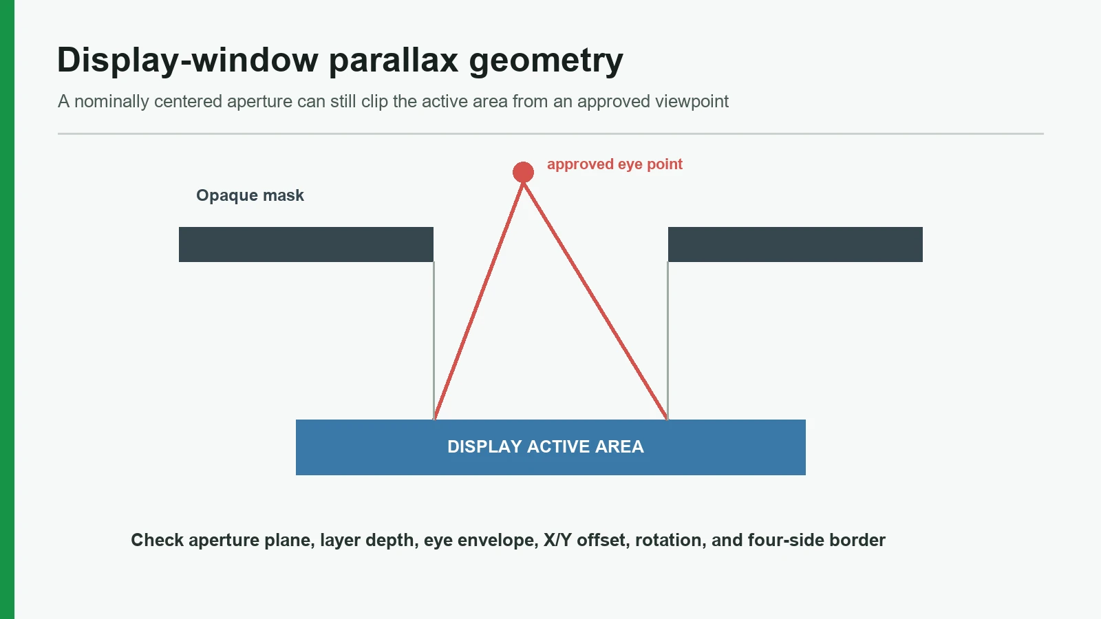
An HMI display window alignment calculation needs two linked models: a ray trace from the required viewpoint to the active plane, and a positional tolerance stack from the active area to the aperture edge. Neither model can rescue a failure in the other. A perfectly centered nominal stack can clip off-axis; a generous optical aperture can still look crooked when production rotation is omitted.
Locate the blocking plane before adding thickness
Start with a section through the edge being checked. The critical reference is the physical plane that contains the opaque edge.
operator eye / external viewing direction
front surface of cover or enclosure
cover material ahead of the blocking edge
OPAQUE MASK OR APERTURE EDGE ← window reference plane
OCA / touch sensor / air gap / other clear layers below that plane
LCD front polarizer and cell
PIXEL / ACTIVE-AREA PLANE
Infineon defines a touch-panel bezel as the opaque perimeter and says it is typically printed on the bottom, or second surface, of the cover lens. See the PSOC 4 CAPSENSE Touchpad Design Guide, Rev. E. If that second-surface print creates the aperture, the layer budget from mask to pixels begins at that print—not automatically at the front of the cover. Layers ahead of the mask still matter when a finite eye position is projected to the mask plane. A first-surface housing bezel, deep counterbore, curved lens, or tilted stack needs its actual section traced.
Calculate layered HMI parallax
For flat, parallel layers, Snell's law relates the external air angle to the ray angle inside each material:
n_air × sin(θ_air) = n_i × sin(θ_i)
The lateral ray travel between the mask plane and active plane is then:
P = g_air × tan(θ_air) + Σ[t_i × tan(arcsin((n_air / n_i) × sin(θ_air)))]
g_air is the air separation below the mask. Each t_i and n_i belongs to a transparent layer in that same mask-to-pixel interval. NIST defines refractive index as the ratio of light speed in vacuum to that in the material; use the approved supplier value at a relevant wavelength and condition. For compound viewing directions, run a 3D ray trace or resolve the displacement by azimuth: P_x = P cos(φ) and P_y = P sin(φ).
For a short viewing distance or a large display, one direction from the eye to the display center is insufficient. Trace each boundary eye position to the relevant AA edges and corners. If the assembly contains more than one opaque opening—such as a printed mask behind a deep housing bezel—test every aperture plane; the controlling edge can change with viewpoint.
The table below is a sensitivity calculation, not a recommended bondline. It shows lateral travel per 1.00 mm of layer at three external angles. The OCA column uses 3M's typical 817X refractive index of 1.4757 at 532 nm. The same 3M OCA 817X data sheet lists actual 8171CL and 8172CL adhesive thicknesses of 25 µm and 50 µm and labels its data representative rather than specification values.
| External angle from normal | Air: travel per 1.00 mm | OCA at n = 1.4757: travel per 1.00 mm | 50 µm OCA contribution |
|---|---|---|---|
| 30° | 0.577 mm | 0.360 mm | 0.018 mm |
| 45° | 1.000 mm | 0.546 mm | 0.027 mm |
| 60° | 1.732 mm | 0.725 mm | 0.036 mm |
An optical bond can reduce a large air separation and change the refractive path, but it does not erase cover, sensor, polarizer, aperture-wall, XY, or rotation effects. “Zero parallax” is therefore not a defensible complete-assembly claim.
Add aperture depth and registration variation
A straight-walled aperture can create tunnel cutoff even when the transparent stack is thin. For an air-filled wall depth h, the front-to-back edge projection in the checked section is B_wall = h × tan(θ_air). A chamfer, flare, radius, or filled cavity needs its real geometry and the ray angle in the relevant medium.
For each left, right, top, and bottom edge e, use a directional budget:
R_e = C_nom,e − (E_reg,e + |P_e| + B_wall,e + I_edge,e)
The edge passes only when R_e ≥ G_e for every required viewpoint and tolerance condition.
The worst edge controls.
| Term | Meaning | Required evidence |
|---|---|---|
| C_nom,e | Nominal clear-aperture extension beyond the active-area edge | Common-coordinate drawing at basic geometry |
| E_reg,e | Declared registration result: AA-to-module, locators, print/cut, assembly translation, component size, and rotation contribution | Worst-case, RSS, Monte Carlo, or capability method named explicitly; corner transform included |
| P_e | Layered optical displacement toward the edge | Approved thicknesses, refractive indices, mask plane, and eye directions |
| B_wall,e | Physical projection of aperture wall or bezel depth | Section geometry, chamfer/radius, and relevant ray angle |
| I_edge,e | Allowed adhesive, gasket, foam, ink, or foreign-feature intrusion | Keep-out drawing and process/inspection limit |
| G_e | Project guard band beyond the calculated boundary | Task risk, UI safe area, measurement resolution, and acceptance owner |
Do not add the same variation twice. If a measured finished-assembly capability already includes print and placement variation, those terms should not reappear as independent stack contributors. Conversely, an RSS result is not a substitute for worst-case analysis unless the process distributions, independence assumptions, yield target, and acceptance plan support it. Check corners as transformed 2D geometry; a center-only measurement cannot expose rotation-driven corner loss.
NISTIR 6223, Design for Tolerance of Electro-Mechanical Assemblies, surveys worst-case, linear RSS, nonlinear propagation, numerical integration, and Monte Carlo methods. The report's useful lesson here is not that one method always wins; it is that the response geometry and statistical assumptions must match the chosen method.
One more feasibility check catches windows that have no valid size. In a simple symmetric one-dimensional section, let A be the maximum active-area width, V the minimum width inside which unwanted frame or internal features remain hidden, and R = E_reg + max|P| + B_wall + I_edge + G. The opening must satisfy both W ≥ A + 2R and W ≤ V − 2R. A solution exists only when V − A ≥ 4R. This is a conservative project derivation, not a standard formula. Rotation, corner radii, nonconcentric features, and asymmetric borders require two-dimensional containment. When the simple interval fails, tightening one arbitrary print tolerance is rarely enough; the design needs a smaller Z gap or wall depth, a wider hide region, better locating logic, a reduced viewing envelope, or a different stack.
initial mid-to-upper engineering baseline — confirm before release
The following values are editor-controlled starting inputs for a project that has not yet supplied verified JASPER data. They are intentionally specific so each field can be replaced before release. None is a JASPER capability, certification, warranty, or universal HMI rule.
| ID | initial value to use in the initial calculation | Primary-source basis | Mandatory replacement boundary |
|---|---|---|---|
| P1 | Allocate ±0.20 mm per X/Y axis to finished AA-to-mask registration during concept review. | Newhaven's NHD-7.0-800480AF-LSXP drawing calls out a bezel opening at 156.7 ± 0.2 mm; Riverdi and Winstar examples use ±0.3 mm for unspecified dimensions. See the Newhaven product specification. | Replace with JASPER's measured finished-assembly capability, datum definition, sample size, and calculation method. A component opening tolerance does not prove assembly registration. |
| P2 | Begin with 0.50 mm nominal clear-aperture extension beyond AA on each side, then enlarge it when E_reg + P + B_wall + I_edge + G requires more. | TOPWAY's LMT070DNCFWD-6 manual gives 0.5 mm per side for that model's cover-lens window. | Replace with the selected display, actual mask plane, viewing envelope, hide boundary, and tolerance calculation. Never publish 0.50 mm as universal. |
| P3 | Use 1.0 mm cover glass and n = 1.50 at 590 nm for the preliminary ray trace. | Corning's large-format Gorilla Glass sheet lists 0.55, 0.70, 1.0, 1.5, and 2.0 mm options and core refractive index 1.50 at 590 nm. | Replace with the approved cover part, actual thickness tolerance, coating/print surface, refractive-index condition, and supplier revision. |
| P4 | Use 50 µm OCA, n = 1.4757 at 532 nm, and 0.3% haze on LCD glass as the initial adhesive input. | 3M lists those conditioned values for 8172CL in the OCA 817X technical data sheet. | Replace with the released adhesive, lot/specification values, bondline tolerance, substrates, and final-stack optical results. Do not publish the haze value as assembly performance. |
| P5 | Inspect at 25 ± 2°C, 60 ± 10% RH, 300–700 lux, 35 ± 5 cm, and ±45° in four directions. | Riverdi publishes those conditions for inspection of RVT70HSDNWC00. | Replace with the product's task, real eye box, illumination, temperature, display state, fixture, and acceptance criteria. |
| P6 | Humidity screen: +50°C, 90% RH, 96 hours. | Newhaven publishes this condition for NHD-7.0-800480AF-LSXP. | Replace with the OEM environment, current IEC method when applicable, sample count, power state, and pre/post alignment limits. |
| P7 | Thermal-shock screen: −20°C for 60 minutes → +70°C for 60 minutes, 20 cycles. | Newhaven NHD-7.0-800480AF-LSXP quality table. | Replace with the product severity and acceptance plan; this model-level screen is not a field-life claim. |
| P8 | Vibration screen: 10–50 Hz, 5 G, 30 minutes on each X/Y/Z axis. | Newhaven NHD-7.0-800480AF-LSXP quality table. | Replace with the installation spectrum, fixturing, powered state, axis definition, and post-test viewing-zone limits. |
| P9 | ESD screen: air ±8 kV, contact ±4 kV, 5 applications each. | Newhaven NHD-7.0-800480AF-LSXP quality table. | Replace with the applicable product standard, discharge points, polarity sequence, operating mode, and functional acceptance criteria. |
The table is a replacement manifest, not permission to combine unrelated component tests into a certification claim. Before release, every P-item needs either verified JASPER evidence or an OEM-approved project value.
A 10-Point HMI Viewing Angle Design Review
A sound HMI viewing angle design review converts operator positions into drawing controls, process limits, and final-stack evidence. The ten checks below are ordered by dependency: definitions and use geometry come first; construction and qualification follow. Skipping an early item usually creates a false sense of precision later.
| # | Review criterion | Acceptance evidence | Release-stopping release blocker |
|---|---|---|---|
| 1 | Drawing entities | AA, VA, clear aperture, mask edge, sensor AA, module outline, and UI safe area are separately labeled. | One rectangle called “screen,” with no supplier terminology check. |
| 2 | Required viewing envelope | Eye positions have X/Y/Z bounds, distance, azimuth, elevation, task, and ambient conditions. | A catalog phrase such as “wide view” replaces user geometry. |
| 3 | Blocking plane | A section identifies the exact print, coating, wall, or bezel edge that cuts the ray. | Total cover thickness is added or ignored without locating the opaque edge. |
| 4 | Datum and registration chain | The AA-to-module relationship flows through measurable locators to the front-panel aperture. | The window is centered only to the LCD outline or a screenshot. |
| 5 | Translation and rotation | The declared stack method covers X/Y shift, component size, locator clearance, print/cut, placement, cure drift, and corner rotation. | Nominal centering or a center-point measurement is the only evidence. |
| 6 | Optical and wall geometry | Every required direction has a layered ray trace and aperture-section check. | The total Z stack is multiplied by one air angle, or wall depth is ignored. |
| 7 | Air gap versus bond | Optical, touch-noise, stress, service, repair, and process consequences are recorded. | Optical bonding is selected as a slogan rather than a project construction. |
| 8 | Edge intrusion and Z control | Ink spread, adhesive, gasket, foam, bow, compression, and allowed overflow have keep-outs and inspection limits. | Soft materials are modeled at nominal thickness with zero lateral intrusion. |
| 9 | Measurement conditions | Image pattern, luminance state, illumination, distance, angles, temperature, sample state, and pass criteria are fixed. | A bare-panel viewing-angle number becomes the finished-HMI specification. |
| 10 | Sample approval and change control | Worst-condition samples, reports, source revisions, and revalidation triggers are approved. | Only nominal samples are signed, or display/adhesive substitutions bypass review. |
1–3: Establish the correct coordinate and viewing frames
The source drawing should carry an explicit coordinate glossary. Microchip's maXTouch Sensor Design Guide is useful because Figure 2-9 separately labels the display active-area edge, sensor active-area edge, lens-decoration print edge, trace-to-decoration tolerance, and display-to-decoration tolerance. It does not supply a universal HMI clearance; the boundaries are distinct design entities.
Define the eye envelope in the product coordinate system, not merely as four symmetric angles. A wall-mounted control, a seated vehicle display, and a handheld service tool can put the eye above, below, or across the display at different distances. Convert each boundary point to a viewing direction at the relevant aperture plane, then test the entire envelope. If multiple operators must see the display, list each required eye box and task. A maintenance-only cross-view may use different criteria from the primary operator's alarm-reading position.
The mask plane is equally concrete. A second-surface ink border, a molded front-wall opening, and a metal bezel can share the same nominal XY aperture while producing different ray paths. Review the section, not just the front view.
4–6: Make display window registration buildable
Display window registration needs an optical reference and a production datum chain. The eye judges the pixel boundary and border symmetry; the assembly process locates physical features. Relate the display AA to the display outline or specified locators, those locators to a carrier or bracket, and the carrier to the panel datums. Then relate the mask or cut aperture to the same finished coordinate system.
ISO 5459:2024 defines terminology and methodology for datums and datum systems. ISO 1101:2017 and ASME Y14.5-2018 (R2024) provide alternative geometrical-specification languages. Pick the organization's released system and use it consistently. These standards do not dictate a particular HMI locator; functional contact and inspection access do.
A visual AA datum may be measurable by a camera even when it cannot locate the part during assembly. That can be acceptable: hard features control placement, and final vision inspection closes the chain to the pixels. The review should state which relationship is controlled by tooling, which is supplier data, and which is verified only on the finished unit. For the broader mechanical method, hand off the full assembly analysis to the related HMI panel tolerance stack and datum planning article rather than duplicating it here.
7–8: Select the stack without treating one construction as universal
Reducing the air gap or using an optical bond can lower mask-to-pixel ray travel and remove an air interface. That does not make optical bonding the default. Infineon's Rev. E touchpad guide says some capacitive designs retain a small, constant air gap because it can reduce display-noise coupling. A separable gap may also support module replacement. An optical bond may be preferable when the viewing envelope, ambient optics, impact architecture, or Z-height requires it—but only after stress, material, process, and service behavior are qualified.
This is where the recommended construction is not the best choice: do not force optical bonding when the touch architecture depends on controlled electrical separation, when field service requires independent display replacement, when the selected cover/display pair cannot tolerate bond or cure stress, or when no qualified production and rework route exists. Conversely, do not retain a large air gap when the edge budget fails or off-axis readability cannot be met.
For a PCAP construction, coordinate the window with touch panels with a display window. The detailed air-gap/perimeter/full-bond trade belongs in the related capacitive touch display window optical stack guide. This article uses that choice only as an input to alignment and viewing-zone approval.
Ink, foam, gasket, and adhesive are not passive annotations. A compressed gasket can move the module in Z or XY. A printed edge can vary by screen, fixture, substrate stability, or cure. A perimeter tape can creep before clamp load is established. Put allowable inward intrusion and minimum/maximum Z stack on the drawing, then inspect the actual edge—not just the die-cut outline before assembly.
9–10: Approve the assembled viewing zone, not the panel alone
The Riverdi module discussed earlier lists an 85° typical viewing angle where contrast ratio is greater than 10, measured at the LCD center with a conoscope. Its inspection section separately uses a 35 ± 5 cm viewing distance, 300–700 lux, and ±45° directions. Winstar's example also ties its angle to CR ≥ 10, a specified temperature, distance, and instrument. These are legitimate product conditions, not interchangeable acceptance criteria.
IEC 61747-30-1:2012 makes the boundary explicit: its transmissive-LCD module measurement scope excludes a module combined with a touch panel or front light, which is removed before measurement. The bare module data help select a display. They do not qualify the final cover, aperture, bond, sensor, ambient condition, or physical cutoff.
Use ISO 9241-303:2011 as a current image-quality requirements framework and ISO 9241-306:2018 for field-assessment scope. The OEM still owns the actual task, environment, viewing envelope, sample plan, and pass criteria. Freeze those conditions with the approved sample and require review when the display, cover, mask artwork, adhesive, gasket, locator, enclosure, or UI safe area changes.
Six Steps from Drawing Inputs to Production Release
The release process should close geometry, construction, and inspection in that order. Running these six steps prevents an attractive nominal prototype from becoming the only alignment specification.
Step 1 — Collect source drawings and use conditions
Request the native display drawing and data sheet, not a sales-page diagonal or screenshot. Add the cover/overlay artwork, mask-edge definition, touch drawing, carrier and enclosure CAD, adhesive/gasket specifications, UI safe-area image, orientation, and service boundary. Record every required eye position or eye box, viewing distance, task, ambient illumination, and temperature condition. Unknown inputs remain open actions; they are not filled with “typical” values.
Step 2 — Normalize entities, units, datums, and revisions
Build one coordinate table for AA, module outline, locating features, sensor AA, mask aperture, housing opening, and critical UI content. Resolve supplier origins, 90° display rotation, front-versus-rear views, and millimeter-versus-pixel dimensions. Identify the physical mask plane on a section. Give every source a part number, revision, and date so that a later display or artwork substitution cannot masquerade as the approved geometry.
Step 3 — Calculate each edge and corner
Transform the maximum AA and minimum aperture through the chosen datum chain. Apply the declared worst-case or statistical tolerance method, including rotation at corners. Project every boundary eye position through the layered stack, then add wall projection and allowed edge intrusion. Report residual margin separately for left, right, top, and bottom; retain the worst viewpoint and tolerance contributor for each. If the hide/no-cut feasibility interval closes, change the architecture before sample tooling.
Step 4 — Choose the construction and build boundary samples
Select air gap, perimeter bond, or optical bond only after Step 3 exposes the required Z and edge behavior. Build representative parts with the real mask, cover, display, sensor, adhesive or gasket, locators, clamp load, and enclosure. The sample set should exercise credible boundary combinations: XY shift, clockwise/counterclockwise rotation, minimum/maximum Z, aperture and AA size limits, and maximum allowed inward edge intrusion. A nominal golden sample alone cannot demonstrate margin.
Step 5 — Validate the completed HMI
Display edge bars, corner markers, fine text, target colors, low-contrast states, and critical UI content. Check from every required eye position under the released illumination and temperature conditions. Record physical cutoff, border symmetry, color or contrast loss, reflections, adhesive/gasket intrusion, and touch-coordinate behavior when touch is present. Repeat relevant checks after environmental and mechanical exposure. Photographs help, but controlled geometry and measured results must identify the sample and condition.
Step 6 — Release the drawing, sample record, and change boundary
The production package should contain the common-coordinate drawing, tolerance calculation, mask and stack section, bill-of-material revisions, assembly work instruction, inspection fixture or eye-position definition, acceptance criteria, and signed sample report. Change control must cover at least the LCD, cover/overlay, mask artwork, touch sensor, adhesive, gasket, locator, enclosure wall, assembly sequence, and UI safe area. A change that preserves the outer dimensions can still move the active image or mask edge.
Failure Chain and Viewing-Zone Validation Matrix
Alignment failures become easier to diagnose when the input error, physical mechanism, visible symptom, and verification step remain connected. Re-centering the artwork may hide one sample's symptom while leaving the actual datum or Z-stack problem untouched.
| Input or process error | Physical mechanism | Observed symptom | Prevention or verification |
|---|---|---|---|
| AA and VA are treated as the same boundary | Window is sized to the wrong rectangle | Pixels clip, or unwanted frame becomes visible | Compare supplier AA, VA, outline, and offsets on one coordinate drawing |
| Window is centered to module outline only | AA-to-outline offset enters the finished assembly | Unequal border reveal despite compliant outer fit | Carry AA-to-datum data through the locating chain; inspect finished AA-to-mask position |
| Rotation is omitted | Error grows with radius from the rotation center | One corner clips while the diagonal corner shows excess opening | Transform all four AA and aperture corners at both rotation limits |
| Mask plane is misidentified | Wrong optical thickness enters the ray trace | Calculated HMI parallax does not match the sample | Section the stack and identify the exact opaque surface |
| Air gap or wall depth is omitted | Off-axis ray footprint moves beyond the remaining edge margin | Image is complete head-on but cuts off from one side | Trace every viewing-envelope boundary and include aperture-wall projection |
| Adhesive, gasket, or ink intrusion is absent from the model | Soft or printed feature enters the nominal clear area | Local dark edge, wedge, or lot-to-lot asymmetry | Release inward-intrusion limits and inspect after final assembly/compression |
| Bare LCD angle becomes the HMI requirement | Electro-optical and physical-cutoff criteria are conflated | Image retains contrast but the bezel hides content | Validate the complete stack; retain the panel criterion only as component evidence |
| Display or mask revision changes without revalidation | AA offset, viewing cone, print edge, or thickness changes | Previously approved margin disappears | Trigger drawing comparison, calculation update, and boundary-sample review |
Validation matrix
The project plan should connect to documented HMI assembly testing and quality controls, but a capability-page link is not test evidence. The signed report must identify the tested construction, sample revision, condition, instrument or fixture, result, and acceptance criterion.
| Review gate | Samples and conditions | Method / evidence | Project acceptance decision |
|---|---|---|---|
| Dimensional registration | Minimum aperture, maximum AA, declared XY/rotation boundaries, compressed stack | Vision or coordinate measurement from released datums; four edge and corner residuals | Every R_e meets its guard band; no uncontrolled datum or double-counted term |
| Normal-view appearance | Final stack at nominal eye position and operating image states | Border-symmetry record, edge pattern, UI safe-area image | No prohibited cutoff or exposed internal feature; cosmetic asymmetry within released limit |
| Viewing-envelope extremes | Every X/Y/Z eye-box boundary, closest and farthest required distances | Fixed fixture or surveyed eye coordinates; edge/corner test pattern | Required content remains visible and readable at each approved position |
| Optical performance | Released illumination, temperature, display drive, cover state, and image set | Final-stack luminance/contrast/color or visual method chosen for the task | Project limits met; component data-sheet angle is not substituted |
| Touch behavior, when fitted | Same viewing positions plus required fingers, gloves, moisture, and grounding states | Coordinate targets, edge accuracy, noise/SNR, false-touch check | Touch and visible target remain acceptably registered under the product's touch specification |
| Edge-intrusion process | Maximum allowed print spread, adhesive flow, gasket/foam compression, and bow | Section/photo/vision record after cure and clamp | No material crosses its keep-out; Z stack remains inside the released range |
| Environmental delta | Pre/post conditions selected from the actual use profile | Repeat registration, optical, touch, bubble/delamination, and viewing-zone checks | No change beyond the project's dimensional, optical, cosmetic, or functional limits |
| Change qualification | Proposed alternate display, artwork, cover, adhesive, gasket, or locator | Redline drawings, updated calculation, representative boundary samples | Release only after affected requirements pass again |
IEC 60068-2-14:2023 covers change-of-temperature testing. IEC 60068-2-78:2025 covers steady-state damp heat at constant temperature without condensation. They provide methods, not the HMI's severity, sample count, powered state, service life, or pass limits. The OEM must supply those choices. Likewise, ASTM D1003-21 measures haze and luminous transmittance of essentially transparent planar plastics; an adhesive or film coupon result does not qualify the assembled viewing zone.
The same discipline applies to inspection uncertainty. If the measured residual lies close to a specification boundary, the release plan must define how measurement uncertainty affects acceptance. A photo that “looks fine” cannot resolve a sub-millimeter edge budget unless its perspective, scale, and measurement method are controlled.
HMI Display Window Drawing and Sample-Approval Checklist
A review can start once the OEM supplies enough information to reconstruct the active image, aperture, stack, locator chain, and viewing envelope. Use the checklist below as the handoff package.
Display and UI inputs
- [ ] Display manufacturer, exact part number, data-sheet revision, and native mechanical drawing
- [ ] AA width/height, corner shape, X/Y location from module datums, and positional tolerance or inspection evidence
- [ ] Module outline, frame/VA definitions, polarizer limits, FPC route, and allowed clamp/contact zones
- [ ] UI resolution, orientation, critical edge content, and a marked UI safe area
- [ ] Display optical conditions: viewing-angle criterion, luminance state, drive, temperature, and measurement method
Window, mask, and stack inputs
- [ ] Cover/overlay CAD and artwork with clear-aperture edges, radii, mask plane, print tolerance, and revision
- [ ] Layer sequence from front surface to active plane, with minimum/maximum thickness, bow, compression, and refractive index where used
- [ ] Air-gap or bond construction, adhesive/gasket/foam part numbers, edge keep-outs, allowed intrusion, and service boundary
- [ ] Housing or bezel section with wall depth, initial, chamfer, radius, and locator geometry
- [ ] Touch-sensor AA, decoration/trace keep-outs, controller/grounding constraints, and final tuning state when touch is fitted
Optical material selection, tint, haze, and hardcoat requirements should be resolved in the related graphic overlay display window design workstream. Only the approved optical and dimensional values return to this alignment calculation.
Use and acceptance inputs
- [ ] Product orientation and one bounded eye box for every required operator or service position
- [ ] Minimum/maximum viewing distance, azimuth, elevation, and any cross-view requirement
- [ ] Task-critical content, illumination, temperature, cleaning state, vibration or motion state, and required gloves or moisture condition
- [ ] Pass criteria for physical cutoff, exposed internals, border asymmetry, image quality, touch registration, and cosmetic defects
- [ ] Tolerance method, yield target when statistical, measurement uncertainty rule, sample count, and acceptance owner
Approval and change-control records
- [ ] Four-edge/corner calculation with assumptions and the worst contributor for each viewpoint
- [ ] Boundary-sample matrix covering translation, rotation, Z stack, aperture/AA size, and edge intrusion
- [ ] Final-stack test report with sample serials, fixtures, images/data, deviations, and disposition
- [ ] Approved master artwork, source drawings, bill of materials, work instruction, and inspection plan
- [ ] Revalidation triggers for display, cover, mask, touch sensor, adhesive, gasket, locator, enclosure, process, and UI changes
The next action is concrete: share the display active-area drawing and the required viewing envelope. Without both, a manufacturer can review fit and appearance, but it cannot close HMI parallax or no-cutoff margin honestly.
Release Blockers That Should Stop Release
Any one of these conditions can invalidate the alignment approval, even when the nominal prototype looks centered:
Stop the release.
- No controlled active-area location. The display drawing gives an outline but no AA offset, tolerance, or finished-part measurement route.
- No physical definition of the aperture edge. Artwork shows a window, but the section does not identify the opaque print or bezel plane.
- A catalog angle is used as the viewing envelope. The source omits the operator position, task, ambient condition, and physical-cutoff check.
- Rotation is absent from the tolerance model. Only X/Y center shift is budgeted, although corner reveal is a release characteristic.
- One universal clearance is copied from another module. A model-specific 0.5 mm instruction, supplier rule, or old drawing replaces the current geometry calculation.
- Soft materials have no released limits. Gasket compression, adhesive flow, foam recovery, or print intrusion can consume clear area without failing incoming dimensions.
- Optical bonding is claimed to solve every alignment issue. XY error, cover/sensor thickness, wall depth, service, stress, and touch behavior remain open.
- Change control stops at outer dimensions. Alternate displays, covers, artwork, or adhesives can preserve fit while changing AA position, optical path, or visible edge.
Frequently Asked Questions
What is HMI display window alignment?
HMI display window alignment is the controlled relationship between the LCD active area and the physical clear aperture or opaque mask in the finished front panel. A complete specification covers nominal centering, four-edge clearance, rotation, layer height, off-axis ray travel, edge intrusion, and the required operator viewing envelope.
How is HMI parallax calculated?
HMI parallax is calculated by tracing the viewing ray from the opaque mask plane to the active plane through each intervening layer. Apply Snell's law to obtain the ray angle in each material, multiply each layer thickness by the tangent of its internal angle, and sum the lateral travel. Add an air gap as `g × tan(θ_air)`.
How much larger should the display window be than the LCD active area?
There is no universal clearance. Each edge needs enough nominal extension to cover registration variation, off-axis ray travel, aperture-wall projection, allowed adhesive or gasket intrusion, and the project guard band. The window must also remain small enough to hide frame, traces, adhesive, or other unwanted features at every approved viewpoint.
Is the LCD viewing angle the same as the finished HMI viewing zone?
No. An LCD viewing angle is an electro-optical component result tied to a criterion such as contrast ratio, a measurement position, and stated conditions. The finished HMI viewing zone also includes the real cover, touch layer, gap or bond, mask, bezel depth, ambient condition, UI task, and physical cutoff from required eye positions.
Does optical bonding eliminate HMI parallax?
No. Optical bonding can reduce physical separation and change the refractive path compared with a large air gap, but it does not remove cover or sensor thickness, aperture-wall projection, XY shift, rotation, or edge intrusion. It may also be the wrong construction when touch-noise separation, field service, stress, or process qualification favors a controlled gap.
Which datum should control display window registration?
Use a measurable functional datum chain that connects the active-area location to the display locators, carrier or bracket, front panel, and mask aperture. The pixels are the visual reference, while physical features usually locate the parts. Final vision inspection may be needed to close the relationship between production datums and the visible active area.
How should rotation be checked in an HMI display window?
Check rotation by transforming all active-area and aperture corners at both angular limits, not by measuring only the center. Rotation error grows with distance from its center, so the controlling condition is often a corner viewed from an oblique eye position. The sample matrix should include clockwise and counterclockwise boundary builds.
What should an OEM send for an HMI display window review?
Send the display part number and native drawing, AA dimensions and offsets, cover or overlay artwork, aperture and mask plane, full layer stack, locators and enclosure section, adhesive or gasket limits, touch drawing, UI safe area, required eye positions, environment, tolerance method, and acceptance criteria. The display active area and viewing envelope are the minimum starting pair.
Share the Display Active Area and Viewing Envelope
The usable HMI viewing zone is the intersection of two envelopes: the assembly's geometric line of sight through every physical opening, and the display's optical performance under the required task and environment. Both must pass. Send the native display drawing, mask/aperture artwork and section, stack dimensions, locating scheme, UI safe area, and bounded eye positions before the enclosure or print is frozen.
Technical References
- Source: active area. Accessed 2026.
- Source: Riverdi Rev. 1.0 data sheet. Accessed 2026.
- Source: Winstar module data sheet. Accessed 2026.
- Source: PSOC 4 CAPSENSE Touchpad Design Guide. Accessed 2026.
- Source: refractive index. Accessed 2026.
- Source: 3M OCA 817X data sheet. Accessed 2026.
- Source: Design for Tolerance of Electro-Mechanical Assemblies. Accessed 2026.
- Source: Newhaven product specification. Accessed 2026.
- Source: OCA 817X technical data sheet. Accessed 2026.
- Source: maXTouch Sensor Design Guide. Accessed 2026.
- Source: ISO 5459:2024. Accessed 2026.
- Source: ISO 1101:2017. Accessed 2026.
- Source: ASME Y14.5-2018 (R2024). Accessed 2026.
- Source: IEC 61747-30-1:2012. Accessed 2026.
- Source: ISO 9241-303:2011. Accessed 2026.
- Source: ISO 9241-306:2018. Accessed 2026.
- Source: IEC 60068-2-14:2023. Accessed 2026.
- Source: IEC 60068-2-78:2025. Accessed 2026.
- Source: ASTM D1003-21. Accessed 2026.
Review the complete HMI assembly before design release
Send the front-panel drawing, stack, display, circuit, connector, enclosure, service conditions, and acceptance plan for review.