
An HMI panel tolerance stack must trace every in-plane and Z-axis variation from functional enclosure datums to the printed window, touch sensor, display active area, bezel, gasket, and rear mount. Start with deterministic worst case; use statistics only after stable process and measurement data exist.
This guide is for mechanical, HMI, quality, manufacturing, and supplier engineers preparing a front-panel assembly for design release or quotation. It decides how to define the datum path, split the functional loops, allocate tolerances, and specify proof. It does not supply a universal clearance, gasket squeeze, Cpk target, or compliance claim. Those values belong to the selected components, processes, operating conditions, and released drawings.
1. What an HMI panel tolerance stack must decide
An HMI panel tolerance stack is a signed model of how part geometry and assembly variation affect one functional result. It is not a list of every tolerance on every drawing. A useful stack ends at a requirement that can pass or fail: minimum visible border, maximum window offset, positive bezel clearance, gasket compression range, flushness, or connector clearance.
Front-panel teams usually need four answers:
| Functional result | Question the stack must answer | Typical failure if it is omitted | Approval evidence |
|---|---|---|---|
| Visual alignment | Does the printed clear opening continue to reveal the required display area at every allowed X, Y, and rotational condition? | Uneven black border, clipped pixels, exposed display edge | Measured border/overlap at all four sides and corners |
| Touch registration | Does the touch-active region remain clear of bezel, mask, seal, and stress zones? | Edge inaccuracy, false touch, restricted usable area | Mechanical clearance plus functional edge-touch check |
| Z height and seal | Do the cover, adhesive, bezel, gasket, hard stops, and enclosure produce an allowed closed gap and surface relationship? | Under-compressed seal, over-compressed gasket, bowed panel, glass load | Closed-gap, flatness, compression, and leakage/ingress evidence |
| Rear integration | Do carrier features, PCB bosses, fasteners, FPC, connector, and enclosure remain compatible? | Cross-threading, connector preload, cable pinch, display twist | Fit, torque/stop, cable-route, and service checks |
The sourcing boundary matters. If an organization buys only a graphic overlay, it retains responsibility for the display, carrier, enclosure, and total stack. If it buys enclosure-mounted front panel HMI assemblies, the supplier review can cover more interfaces—but the released product definition still needs one owner.
ASME describes Y14.5-2018 (R2024) as the common language for expressing and interpreting GD&T on drawings and digital models. ISO 5459:2024 provides terminology and methodology for datums and datum systems, while ISO 1101:2017 covers geometric specification language for form, orientation, location, and run-out. Neither system chooses the HMI datums or tolerance values; the design team must derive those from function and assembly.
2. How to choose the HMI front panel datum
The HMI front panel datum scheme should reproduce how the assembly seats, locates, and clocks in the enclosure. Decorative edges, laser-cut blanks, display outlines, and flexible gasket faces are weak references unless they actually control that relationship in assembly.
A common functional pattern is:
- Primary datum A: the rigid seating or sealing-support plane that establishes front-to-back position and tilt.
- Secondary datum B: a hard locating feature, feature pattern, or derived center plane that establishes the critical in-plane direction.
- Tertiary datum C: a second feature, slot, or edge that clocks the assembly without adding an unnecessary conflict.
That pattern is a design inference, not a universal ASME or ISO prescription. A product that first seats on a carrier, for example, should not pretend that its decorative front face controls the same degrees of freedom. The order of contact, the locating features, clamp loads, service strategy, thermal movement, and inspection method decide the useful hierarchy.
Each detail part also has its own real datum features. The cover, sensor, display frame, carrier, PCB, and enclosure do not inherit one datum label by proximity. Their individual reference frames must map through physical interfaces:
Functional enclosure reference frame A0 · B0 · C0
Front flange / bezel A1 · B1 · C1
cover outline or hard locators
printed black mask and clear aperture
gasket land and closed hard stops
Carrier / PCB boss pattern A2 · B2 · C2
display mounting features
display active area from the controlled module drawing
Touch-sensor locating frame A3 · B3 · C3
touch active area, border, electrodes, and FPC keep-out
Functional response = relationship among the branch endpoints,
not merely the tolerance of any one branch.
This map exposes a frequent drawing error: a window width may be tightly toleranced while its location and orientation remain weakly controlled. ISO 14405-1:2025 addresses linear size and explicitly does not establish the functional relationship by itself. In practical terms, the release package must control aperture size and the geometric relationship that matters to the display, sensor, and enclosure.
Before naming A, B, and C, answer five questions:
- Which surfaces or locators touch first during normal assembly?
- Which feature must remain visually centered: the module outline, viewing area, or active pixel area?
- What prevents shift or rotation before adhesive cure or fastener seating?
- Where can production tooling and inspection equipment simulate the intended reference frame?
- Does the design need controlled float for thermal movement or service replacement?
If the drawing and the assembly fixture answer those questions differently, the fixture will create an undocumented datum scheme. Correct the design or document the fixture relationship before allocating tighter tolerances.
3. Build four functional loops instead of one oversized stack
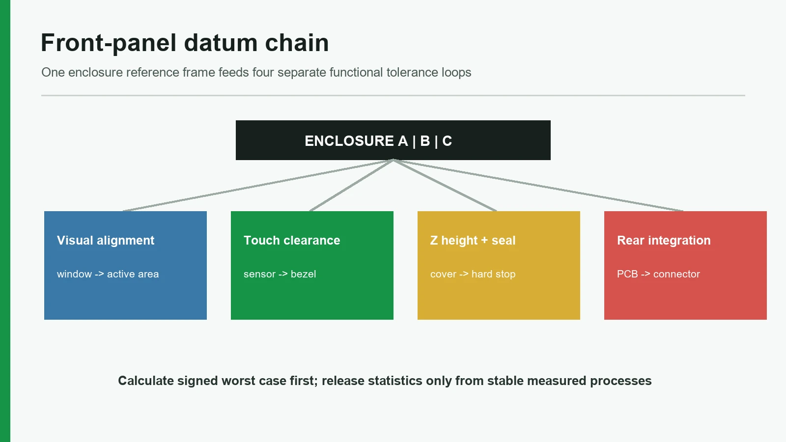
A front-panel assembly needs separate loops because X/Y alignment, rotation, Z height, gasket compression, and rear clearances do not share the same response or evidence. Combining them in one spreadsheet hides sign, units, and failure boundaries.
| Loop | Start and endpoint | Include | Release decision |
|---|---|---|---|
| Visual X/Y/rotation | Printed clear aperture or black mask to display active area | Print registration, cover location, sensor/cover registration, display active-area location, carrier/boss location, assembly float, angular error | Minimum overlap and maximum border asymmetry at every edge/corner |
| Touch registration | Bezel/mask/gasket boundary to touch-active and electrode regions | Sensor location, border, bezel clearance, gasket edge, cover stack, controller-specific keep-outs | No forbidden contact; required edge-touch region remains usable |
| Z height/seal | Front seating plane to cover/display faces and gasket land | Cover, adhesive, touch/display stack, bracket, hard stops, gasket free thickness, closed gap, enclosure flatness | Flushness, allowed glass load, minimum/maximum gasket compression |
| Rear interface | Front reference frame to PCB, bosses, fasteners, FPC, and connector | Boss height/location, board holes, bracket, fastener seating, cable bend/keep-out, service path | Assembly without preload, pinch, cross-thread, or inaccessible inspection |
Visual loop: define HMI display alignment tolerance at the active area
An HMI display alignment tolerance should be a functional relationship between the visible aperture and the display's controlled active or viewing area—not a blanket tolerance between two outer rectangles. A current Newhaven display drawing, for example, gives different limits to the module outline, bezel opening, polarizer, FPC, and other features. That is evidence that the product drawing, not a nominal diagonal size, must feed the stack. See the named NHD-7.0-800480EF-ASXN drawing; its values apply only to that module.
Rotation deserves its own term. A small angular deviation can produce acceptable centering near the display center but consume overlap at a far corner. For a point at radius (r) from the rotation center and a small angular error (\theta) in radians, the tangential displacement is approximately (r\theta). Check all four corners rather than approving only center-to-center offset.
When the display module sits inside the supplier's scope, a display-integrated HMI assembly can reduce handoffs. It does not remove the need to identify the active area, window, mask, locating features, and inspection method on controlled documents.
Touch loop: separate sensing boundaries from the visible window
The touch-active region, electrode border, FPC exit, display active area, and visible opening may have different origins and dimensions. That makes touch panel assembly tolerance a separate loop. Elo's product-specific TouchPro PCAP Integration Guide requires the bezel and cover-glass tolerance combination to retain positive edge clearance at worst case and recommends a fixture to align the touchscreen and LCD. Newhaven's analog-resistive guide uses a hard mechanical stop for the panel-to-bezel relationship and warns against making a front gasket the precision gap stop. These are valuable design patterns, but their numeric limits remain product-specific.
Touch calibration can compensate for coordinate translation, rotation, and scaling within the controller's supported model. It cannot recenter a printed mask, create bezel clearance, remove gasket pressure, unload glass, or free a pinched FPC. Keep software calibration out of the mechanical acceptance budget.
Z loop: calculate the hard gap before selecting the gasket
The Z loop should distinguish rigid geometry from compliant material. Establish the minimum and maximum closed gap from hard parts and stops, then compare both extremes with the selected gasket's free-thickness limits and compression-force-deflection data. Rogers' enclosure-seal guidance also calls out secondary layers such as coatings and adhesives; leaving them out makes the nominal gap look safer than it is.
For gasket free thickness (t_f) and a hard-stop gap (g), the geometric compression is:
[ Compression\ (%) = 100\left(1-\frac{g}{t_f}\right) ]
That equation does not define an acceptable percentage. The material data, gasket width, flange stiffness, fastener pattern, stress relaxation, environment, and assembled sealing test decide whether the result works.
Rear loop: keep the display flat and the cable free
PCB bosses and fasteners may locate a carrier, retain it, or do both. If a screw pattern pulls a warped or over-constrained carrier into place, the final display position and glass stress can differ from the loose-part inspection. Model the seated condition, including boss heights, bracket contact, fastener hard stops, board holes, and any locating clearance.
Infineon's industrial capacitive touchscreen white paper cautions that touch/display/cover bonding and enclosure mounting should avoid unintended tensile, compressive, and torque loads. It also treats cable placement, liquid drainage, temperature, and nearby electrical sources as system-integration issues. The rear stack therefore needs keep-outs and load paths, not just hole coordinates.
4. How to calculate an HMI panel tolerance stack—and prove it
Calculate an HMI panel tolerance stack in two stages. First, propagate released limits deterministically to test guaranteed assembly. Second, use measured statistical variation only after the process, dependence model, and measurement system are credible.
Start with a signed response equation
For one in-plane direction, define the response before opening a spreadsheet. If (x_i) are signed contributions and (a_i) preserve their direction:
[ y = \sum_i a_i x_i ]
For symmetric released limits (x_i = \mu_i \pm T_i):
[ y_{nom} = \sum_i a_i\mu_i \qquad T_{WC} = \sum_i |a_i|T_i ]
The response might be the X offset between the printed aperture center and the display active-area center. A different sheet should handle Y, rotation, Z height, or connector clearance. Keep units, sign convention, datum frame, part revision, source drawing, and owner beside every contribution.
Worked visual-alignment example
No ASME, ISO, or IEC standard assigns a universal HMI alignment tolerance. The arithmetic below therefore uses a source-backed, mid-to-upper industry-reference profile for initial planning. It is not a JASPER capability or a released requirement. Hard limits remain. Measure the assembly. Replace every row with the selected component drawing and measured production data before the article is published.
| Contribution to aperture-center minus active-area-center, X | Sign | initial value | Source and evidence boundary |
|---|---|---|---|
| Die-cut overlay aperture relative to overlay datum | + | ±0.25 mm | Rounded from the ±0.010 in (±0.254 mm) standard steel-rule-die tolerance in the J.N. White membrane-switch design guide |
| PCAP cover-glass edge used as the locating feature | + | ±0.30 mm | Elo TouchPro PCAP Integration Guide standard-design cover-glass dimension tolerance; delete this term if the design locates from another controlled feature |
| Display active area relative to module mounting datum | − | ±0.30 mm | initial use of the unspecified linear tolerance on the named Newhaven NHD-7.0-800480EF-ASXN drawing; replace with the selected module's actual feature relationship |
| Enclosure or carrier cut feature relative to its datum | − | ±0.25 mm | Conservative sheet-metal reference from Xometry manufacturing standards, which lists ±0.010 in (±0.254 mm) for same-surface cut-feature relationships |
| OCA lens-to-LCD lamination alignment | − | ±0.15 mm | Named process example from the EM Microelectronic Plastic LCD fact sheet; its in-house process value is not transferable to another module or bonding line |
| Worst-case total | — | ±1.25 mm | Sum of absolute initial limits |
| Root-sum-square of the five initial limits | — | ±0.57 mm | Screening value only; not a guaranteed or probabilistic limit |
With this initial profile, a design that requires a guaranteed offset below ±1.25 mm must remove contributors, change the locating architecture, tighten a justified source, increase the allowed overlap, or add an alignment process. Quoting the ±0.57 mm screening result does not remove the ±1.25 mm hard-limit combination. The selected assembly still needs a separate measured allowance for fixture repeatability, cure movement, seating, and locating clearance; no universal value is assigned to those effects here.
Use RSS only with a defensible statistical model
For measured variation, the general linearized form includes sensitivity and covariance:
[ \sigma_y^2 \approx \nabla f \Sigma \nabla f ]
If the terms are genuinely independent and the response is linear, this reduces to:
[ \sigma_y \approx \sqrt{\sum_i (a_i\sigma_i)^2} ]
NIST's propagation guidance requires covariance to be considered where appropriate and identifies unsuspected covariance or a poor response model as failure modes. Do not convert a drawing tolerance to (\sigma) by dividing by three unless distribution, centering, truncation, and process evidence justify that conversion. Adhesive placement, shared tooling, temperature, and common fixture references can correlate terms that look independent on paper.
Use Monte Carlo or a nonlinear model when rotation, clearances, contact state, gasket force, or edge/corner geometry makes the response non-linear. The simulation inputs still need measured distributions and dependencies; software cannot manufacture missing evidence.
Capability belongs to a stable process and a qualified measurement system
For a two-sided characteristic, NIST gives:
[ C_p = \frac{USL-LSL}{6\sigma} ]
[ C_{pk} = \min\left(\frac{USL-\mu}{3\sigma},\frac{\mu-LSL}{3\sigma}\right) ]
(C_p) compares spread with the specification width; (C_{pk}) also reflects off-center operation. The NIST process-capability guidance ties these estimates to an in-control process and notes normality, independence, and sample-size assumptions. It describes about 50 independent observations as a general meaning of “large enough” and says capability studies generally need (n \ge 100). For this initial initial, use 100 independent observations and Cpk ≥ 1.33 as mid-to-upper planning targets for critical alignment characteristics. The 1.33 is among criteria sometimes promoted for a “manufacturable” process; it is not a universal NIST, ASME, ISO, or customer mandate. Replace both targets with the approved customer/control-plan requirements before release.
Capability evidence is weak if the gauge cannot resolve the characteristic or if different inspectors, fixtures, software fits, temperatures, or seating methods change the result. A NIST gauge study treats repeatability, reproducibility, stability, resolution, linearity, hysteresis, and drift as measurement-system concerns. Qualify the measurement system before using Cpk to release a tight stack.
5. The ten-point front-panel interface framework
Use this framework to review the physical chain before approving a supplier drawing or RFQ package. The criteria run from the functional reference frame through visible, touch, sealing, and rear interfaces. A strong package gives each interface a good locating signal, a measurable limit, and an owner.
| Criterion | Acceptance evidence | Release blocker | Required release artifact |
|---|---|---|---|
| 1. Front support/sealing plane | A rigid, accessible surface reflects the seated condition; flatness and contact state are defined where function requires them | Decorative film, foam, or an incomplete rim is treated as a perfect plane | Datum-feature definition, contact-area drawing, flatness/profile requirement, inspection setup |
| 2. In-plane location and clocking | Hard locators reproduce assembly order; any round-pin/slot or center-plane strategy has a stated clearance and purpose | Two parts are both “centered by eye,” or several tight pins over-constrain the assembly | B/C feature definitions, basic locations, fit/clearance model, thermal/service rationale |
| 3. Printed window and black mask | Cut edge, clear opening, black mask, artwork, and adhesive keep-out share a controlled coordinate frame | Print is dimensioned from artwork origin while cutting is dimensioned from an unrelated outer edge | Artwork registration specification, released vector artwork, inspection overlay or vision program |
| 4. Touch sensor | Active area, border, electrodes, FPC exit, and forbidden pressure zones come from the exact sensor drawing | Display active area is copied as the touch boundary, or bezel/gasket contact is not shown | Controlled sensor drawing, border/keep-out map, edge-touch acceptance test |
| 5. Display module | Active area or viewing area is located from functional mounting features on the selected module drawing | Nominal diagonal or module outline is used as the visual datum | Supplier drawing revision, active/viewing-area definition, mounting-feature limits, change notice |
| 6. Carrier, PCB bosses, and fasteners | Locating, retention, and load paths are separated where practical; seated boss height and fastener stops are controlled | Screws are expected to pull misaligned parts into position or flatten glass-bearing structure | Carrier/PCB/enclosure drawings, seated stack section, torque/stop method, distortion check |
| 7. Bezel and hard stop | A rigid feature controls the no-contact gap; worst-case edge clearance remains positive | Foam or gasket is the precision stop, or nominal centering is the only clearance proof | Section view, edge/corner clearance calculation, fixture/alignment method |
| 8. Gasket | Minimum and maximum closed gaps include coating and adhesive layers; selected material CFD and stress relaxation are reviewed | One nominal thickness and one generic compression percentage stand in for a seal design | Gasket TDS, thickness limits, gap stack, compression/load calculation, flange and fastener map |
| 9. Enclosure cutout and flange | Cutout size, location, orientation, flange flatness, finish/coating, and access match the mounting method | A general title-block tolerance is assumed to control a large or formed sealing flange | Enclosure drawing, profile/flatness controls, surface/finish note, mating-part acceptance method |
| 10. Cable, fixture, and inspection access | FPC route, connector engagement, bend/keep-out, assembly fixture, datum simulators, and gauge access are designed together | The cable is folded after closure, or the critical feature cannot be measured in the seated condition | Cable-route drawing, connector datum, fixture concept, gauge plan, service sequence |
The framework also prevents nominal catalog data from turning into false requirements. A 2026 3M membrane-switch spacer data sheet, for example, labels its physical and performance data as representative or typical and unsuitable for specification purposes. A buyer should therefore request controlled thickness limits and process evidence for the selected construction instead of copying a nominal layer value into the stack.
The largest contributors deserve the most attention. Tightening every dimension raises inspection and process burden while a shared datum conversion, floating adhesive operation, or loose carrier locator may continue to dominate the response. Use the signed stack or measured variance contribution to identify which architecture change buys real margin.
For a first-party process example—not performance proof—the JASPER active display area, clear opening, printed mask, and adhesive keep-out as distinct boundaries referenced from a common datum. The anonymized page does not establish customer identity, volume, field life, or numerical capability.
initial industry-reference values
The following values make the initial concrete without presenting them as JASPER data. These are editorial values. They are not specifications. They sit toward the middle or conservative side of the cited supplier guidance. Replace every value with the selected part drawing, approved control plan, and measured JASPER/customer evidence before release.
6. When a shared hard-datum construction is not the best choice
A short, rigid datum chain is usually easier to calculate and inspect, but it is not always the best construction. The functional requirement may favor a controlled compliant or adjustable interface instead.
- A bonded display/touch/cover module arrives as one controlled unit. Treat its internal relationships as supplier-controlled characteristics and design the enclosure interface around the module's released mounting datums. Recreating separate internal datums in the customer drawing can add conflicting requirements.
- Thermal movement or shock needs controlled float. A rigid locator at every layer can transmit load into glass, adhesive, or the touch bond. Use a deliberate fixed/float strategy with positive clearance, retention, and environmental validation rather than simply loosening all tolerances. Infineon's integration guidance makes mechanical stress across the bonded stack an explicit design concern.
- The assembly is actively aligned before cure. Vision alignment or adjustable brackets may deliver better aperture-to-active-area registration than fixed part tolerances. The fixture coordinate frame, cure shift, retention, and post-cure inspection then become process characteristics in the stack.
- The display is field-replaceable. A service bracket with controlled adjustment may be preferable to a permanently bonded, tightly matched stack. Define the service alignment method and acceptance gauge.
- A flexible overlay has no durable hard datum feature. Tooling holes, printed fiducials, or a carrier-based fixture may control registration more honestly than an unstable film edge. The finished assembly still needs a measurable relationship to the enclosure.
Compliant design is not permission to omit limits. It changes the controlled variables from loose-part dimensions to gaps, loads, fixture repeatability, cure movement, retention, and final assembled measurements.
7. A six-step buyer and design-release process
The buyer process should convert functional intent into controlled inputs, calculations, and evidence. Run these six steps before tooling or production release; a late tolerance review cannot repair missing datum features without geometry or process changes.
Step 1 — Freeze the functional requirements and conditions
State what the user must see and touch, what must remain clear, what must seal, and what may move. Include display active/viewing area, permitted border asymmetry, touch edge zones, bezel no-contact areas, flushness, enclosure mounting, cable service, temperature range, liquids/cleaners, UV exposure, vibration/shock profile, and intended ingress target where applicable. Mark each value as system requirement, component limit, initial target, or supplier proposal.
Step 2 — Issue one controlled input package
Send the front-panel and enclosure CAD, 2D drawings, artwork, display and touch module drawings, PCB/boss geometry, gasket land, cable/connector model, assembly section, BOM revisions, and supply-scope boundary. Identify whether the supplier receives the actual display module or only its drawing. A screenshot or nominal outline is not an interface-control document.
Step 3 — Map datums and separate the functional loops
Choose one drawing convention—ASME or ISO—and use it consistently in the release. Map each part's datum features to the physical assembly sequence. Build separate X, Y, rotation, Z/seal, and rear-interface loops with signed terms. Name the requirement, formula, source, revision, units, owner, and inspection method for every row.
Step 4 — Review tolerance sources, capability, and measurement
Challenge every value: Is it a hard drawing limit, a catalog typical, pilot data, a proposed process limit, or a guess? Ask the responsible supplier for recent data from the proposed process, not a different machine or construction. Confirm the process is stable, define the sampling plan, and qualify the gauge or vision method for the seated condition. Record correlation risks when two contributors share tooling or assembly operations.
Step 5 — Build and measure the complete first article
Inspect critical part features, then assemble the real cover, sensor, display, carrier/PCB, gasket, and enclosure with the intended fixture and seating method. Measure all four visual borders or overlaps, corner conditions, bezel/gasket clearances, closed gap, surface relationship, cable route, and fastener/hard-stop state. Run the functional touch checks after mechanical assembly—not only on the bare sensor.
Step 6 — Validate the pilot process and control change
Use pilot units to compare predicted and observed variation. Investigate centering shifts, fixture effects, and measurement uncertainty before quoting capability. Run the application-specific environmental and functional tests at defined severities, then freeze drawings, approved component revisions, fixtures, inspection programs, and change-notification rules. Repeat the affected stack when a display, sensor, adhesive, gasket, carrier, enclosure process, or tooling reference changes.
8. Validate the stack against failure modes
A tolerance calculation is approved only when the assembled product can be measured and challenged under relevant conditions. The matrix below is a planning structure, not a universal test specification. Sample count, conditioning, severity, equipment, measurement uncertainty, and pass/fail limits must come from the project's requirements.
| Failure mode | Condition to include | Measurement or test | Approval evidence |
|---|---|---|---|
| Uneven or clipped display border | Nominal and stack-extreme assemblies; all four corners | Vision measurement of clear-aperture-to-active-area overlap and border asymmetry | Dimensioned image/report tied to part and assembly revisions |
| Bezel or gasket contacts touch-active region | Worst-case X/Y/rotation and closed-gap state | Clearance inspection plus edge-touch functional pattern | Mechanical clearance results and touch log under defined controller settings |
| Glass, sensor, or bond is mechanically loaded | Fasteners seated; min/max hard gap; relevant temperature endpoints | Surface/flatness check, load-path review, functional inspection before/after conditioning | Assembled section verification and anomaly record |
| Seal is under- or over-compressed | Min/max gasket thickness, gap, coating, adhesive, flange variation | Closed-gap measurement, compression/load calculation, leakage or ingress test | Stack report plus test report for the complete enclosure |
| Carrier or PCB distorts display | Torque/stop extremes and representative boss-height variation | Surface relationship, active-area alignment, and touch/display function after seating | Fastener method, seated measurements, and fixture record |
| FPC or connector is pinched/preloaded | Full closure, bend and service sequence | Visual/force/engagement check and electrical function | Cable-route photos or measured clearances, connector acceptance record |
| Vibration changes alignment or retention | Project-defined spectrum, axes, mounting, and powered state | Pre/post dimensional and functional checks | Test report with severity, fixture, axes, duration, and change assessment |
| Dust or water enters the enclosure | Defined enclosure configuration and target classification | Complete-enclosure ingress test | Report tied to exact gasket, fastener, coating, vent, and enclosure revisions |
IEC 60529 classifies enclosure protection against access, solids, and harmful water ingress. An IP claim therefore belongs to the tested enclosure configuration, not automatically to an overlay, gasket, or HMI subassembly. IEC 60068-2-6 provides a sinusoidal-vibration method for finding mechanical weakness or performance degradation at specified severities; the application still has to choose those severities and acceptance limits.
JASPER's internal failure-mode-based testing and validation planning page can support requirement review, prototype evaluation, production control, and change planning. It is not evidence that a particular HMI stack has passed a named test. That proof must come from the project report.
9. Drawing-release and sample-approval checklists
The drawing package and the sample plan should describe the same assembly state. If the drawing controls loose parts while approval measures a clamped, bonded, or calibrated assembly, record the transformation and its owner.
Drawing-release checklist
- [ ] Canonical 3D model and 2D drawings use the same revisions and units.
- [ ] ASME or ISO drawing convention is named; obsolete standard editions are not copied forward.
- [ ] Functional enclosure, cover, sensor, display, carrier/PCB, and gasket datum features are mapped.
- [ ] Active area, viewing area, clear aperture, black mask, adhesive keep-out, touch border, and FPC keep-out are distinct.
- [ ] X, Y, rotation, Z/seal, and rear-interface loops identify sign, source, owner, and requirement.
- [ ] Selected display and touch drawings are controlled by manufacturer part number and revision.
- [ ] Hard stops, locating clearances, fastener seating, boss heights, and assembly sequence appear in a section view.
- [ ] Gasket free-thickness limits, closed-gap limits, material/grade, adhesive/coating layers, and flange requirements are stated.
- [ ] Critical characteristics have an inspection method, datum simulation, equipment, sampling plan, and acceptance limit.
- [ ] Change control covers display, sensor, artwork, adhesive, gasket, carrier, enclosure process, fixture, and inspection program.
First-article and sample-approval checklist
- [ ] Verify BOM, component markings, drawing revisions, artwork revision, and fixture revision.
- [ ] Measure the critical loose-part features that feed each stack; retain raw data.
- [ ] Assemble with the intended cleaning, alignment, cure, seating, fastener, and cable-routing process.
- [ ] Record all four display borders/overlaps and corner conditions in the assembled reference frame.
- [ ] Verify bezel, gasket, electrode, FPC, connector, and service clearances.
- [ ] Measure hard-stop gap, panel relationship, gasket condition, and fastener seating.
- [ ] Run the defined touch grid/edge pattern and display inspection after mechanical closure.
- [ ] Execute required environmental or ingress checks with exact conditions and acceptance criteria.
- [ ] Compare observed assembly variation with the model; explain residuals and update assumptions.
- [ ] Close every deviation through accept, rework, design change, or documented concession before release.
The anonymized JASPER HMI front-panel assembly case is a useful process illustration because it treats graphics, controls, PCB, fasteners, cables, and housing datums as one assembly problem. It does not supply customer, volume, field-life, or capability evidence for a new project.
10. Eight release blockers that stop design release
These release blockers override a polished sample or a tight-looking title-block tolerance. Do not waive them casually. Resolve the datum path first.
| Release blocker | Why it stops release | Required correction |
|---|---|---|
| Dimensions chain from several unrelated outer edges | Each conversion adds uncontrolled position or rotation without a common functional reference | Re-dimension from mapped functional datum features |
| The display outline substitutes for its active area | Nominal module size does not prove visible pixels will align with the printed aperture | Use the selected module's controlled active/viewing-area relationship |
| A compressible gasket acts as the precision Z stop | Seal load and display/touch clearance move with material, flange, and fastener variation | Establish a hard-gap loop and evaluate the gasket separately |
| Catalog typicals appear as guaranteed tolerances | A nominal or representative value is not a supplier commitment | Obtain controlled limits and process evidence |
| RSS replaces worst case without a statistical model | No distribution, stability, sensitivity, independence, covariance, or risk decision supports the smaller result | Retain worst case; justify each statistical input and dependency |
| Cpk arrives without a qualified gauge and stable process record | The index may describe measurement noise or drift rather than capable production | Qualify the gauge, establish control, and retain raw data |
| Touch calibration is the proposed mechanical corrective action | Coordinate mapping cannot restore overlap, clearance, seal load, glass stress, or cable freedom | Correct mechanical geometry; validate calibration separately |
| The critical result cannot be inspected in the seated condition | Undefined datum simulators, access, method, or output make the requirement unenforceable | Design the fixture/gauge and acceptance output before release |
11. Frequently asked questions
What is an HMI panel tolerance stack?
An HMI panel tolerance stack is a signed model that connects permitted part and assembly variation to one functional result, such as display-window overlap, touch clearance, gasket compression, flushness, or connector clearance. It should name the datum frame, direction, source drawing, units, sign, and approval requirement for every contribution.
What should be the primary HMI front panel datum?
The primary HMI front panel datum should usually come from the rigid surface that establishes the functional seated plane, not from decorative film or a compliant gasket. The correct feature depends on assembly order, load path, inspection access, and service strategy; ASME and ISO define datum languages but do not choose the feature for the designer.
What is an acceptable HMI display alignment tolerance?
There is no universal HMI display alignment tolerance. Derive it from the minimum required overlap or permitted border asymmetry between the printed aperture and the selected display's controlled active/viewing area, then include X, Y, rotation, locating clearance, fixture, and inspection uncertainty. Product-specific supplier drawings must provide the input limits.
Should an HMI stack use worst-case analysis or RSS?
Use worst-case analysis first when the assembly must fit across all released limit combinations. Use statistical propagation only when measured distributions, process stability, sensitivity, and covariance are defensible. An RSS of drawing limits is a screening calculation, not a guaranteed limit; capability evidence also needs a qualified measurement system.
How should touch panel assembly tolerance include the bezel and gasket?
Touch panel assembly tolerance should preserve the product-specific clearance between bezel, mask, gasket, touch-active area, electrode border, and FPC at every allowed translation and rotation. A rigid stop should control any no-contact gap when required; gasket compression and touch loading must be evaluated separately with the selected sensor and material documentation.
Can touch calibration correct mechanical display misalignment?
No. Calibration can map touch coordinates for supported translation, rotation, scale, and nonlinearity, but it cannot center a printed window, restore display overlap, create bezel clearance, remove gasket pressure, unload bonded glass, or correct a pinched cable. Mechanical and software acceptance criteria should remain separate.
How is front-panel gasket compression calculated?
Geometric compression is \(100(1-g/t_f)\), where \(g\) is the closed hard-stop gap and \(t_f\) is gasket free thickness. Calculate both gap and thickness extremes, then use the selected material's compression-force-deflection and stress-relaxation data, flange/fastener design, environment, and complete-enclosure test to set acceptable limits.
What should be sent to an HMI assembly supplier for tolerance review?
Send the front-panel and enclosure CAD, controlled 2D drawings, artwork, display/touch drawings and revisions, PCB/boss geometry, gasket land, cable/connector model, assembly section, functional requirements, datum proposal, stack workbook, inspection plan, operating conditions, and clear supply-scope boundary. Identify every initial value so it cannot become an accidental release requirement.
12. Send the front-panel CAD and datum scheme
A useful supplier review starts with the complete coordinate and evidence package, not a screenshot of the opening. JASPER can review the front panel, cover/print, touch and display drawings, carrier or PCB bosses, bezel, gasket land, enclosure interface, cable route, and proposed datum scheme within the agreed supply scope. Send the front-panel CAD and datum scheme for review, with initial assumptions clearly marked.
Technical References
- Source: ASME describes Y14.5-2018 (R2024). Accessed 2026.
- Source: ISO 5459:2024. Accessed 2026.
- Source: ISO 1101:2017. Accessed 2026.
- Source: ISO 14405-1:2025. Accessed 2026.
- Source: NHD-7.0-800480EF-ASXN drawing. Accessed 2026.
- Source: TouchPro PCAP Integration Guide. Accessed 2026.
- Source: Newhaven's analog-resistive guide. Accessed 2026.
- Source: enclosure-seal guidance. Accessed 2026.
- Source: industrial capacitive touchscreen white paper. Accessed 2026.
- Source: J.N. White membrane-switch design guide. Accessed 2026.
- Source: Elo TouchPro PCAP Integration Guide. Accessed 2026.
- Source: Newhaven NHD-7.0-800480EF-ASXN drawing. Accessed 2026.
- Source: Xometry manufacturing standards. Accessed 2026.
- Source: EM Microelectronic Plastic LCD fact sheet. Accessed 2026.
- Source: NIST's propagation guidance. Accessed 2026.
- Source: NIST process-capability guidance. Accessed 2026.
- Source: NIST glossary. Accessed 2026.
- Source: NIST gauge study. Accessed 2026.
- Source: 3M membrane-switch spacer data sheet. Accessed 2026.
- Source: Newhaven analog-resistive integration guide. Accessed 2026.
- Source: Rogers enclosure-seal guidance. Accessed 2026.
- Source: IEC 60529. Accessed 2026.
- Source: IEC 60068-2-6. Accessed 2026.
Review the complete HMI assembly before design release
Send the front-panel drawing, stack, display, circuit, connector, enclosure, service conditions, and acceptance plan for review.