
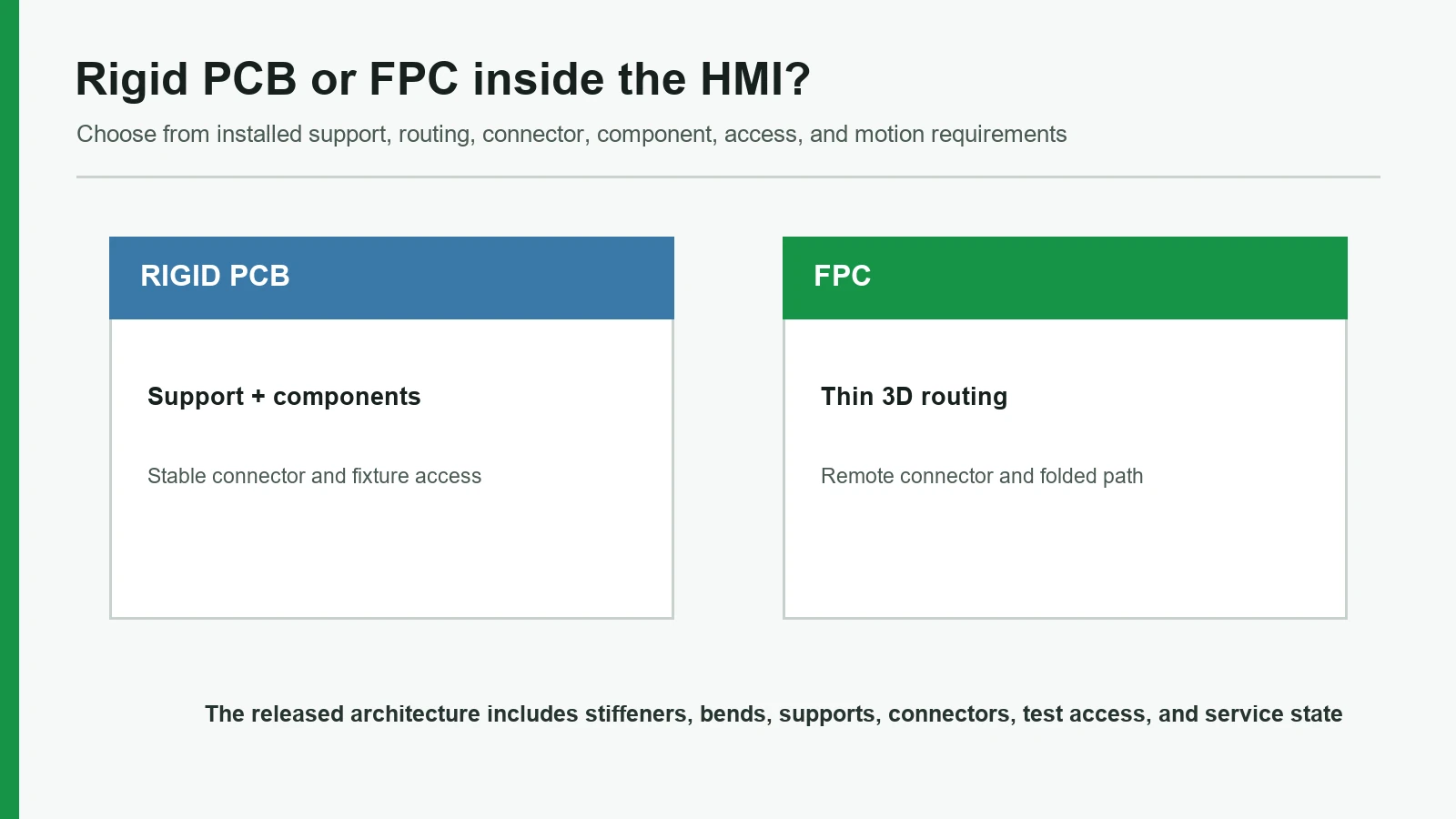
A rigid PCB is usually the better base when the front panel needs structural support, dense components, rigid connectors, or direct test and rework access. An FPC is usually better when the circuit must fold through a thin enclosure, connect separated planes, or reach a remote connector without a separate cable. A PCB FPC HMI assembly decision is therefore about the installed module—not simply FR-4 versus polyimide.

1. PCB vs FPC for HMI Front Panels: Quick Verdict
Choose a rigid PCB when the circuit carrier must also provide a stable location for connectors, components, LEDs, local control electronics, or supported key zones. Choose an FPC when routing—not support—is the main problem: the circuit must cross planes, turn through a housing, pass through a slot, or terminate away from the operator surface. The PCB and FPC HMI assembly route becomes useful when the front controls, circuit, display or indicators, carrier, connector, and output test state must be released as one module.
The answer changes if the FPC must move repeatedly, if a connector needs service access, or if the PCB consumes too much rear depth. “Flexible” does not mean any fold is acceptable. “Rigid” does not mean the board can absorb connector, fastener, or key loads without mechanical analysis.
| Decision dimension | Rigid PCB usually wins | FPC usually wins | Depends on the released design |
|---|---|---|---|
| Stable platform for dense or tall components | ✓ | ||
| Rigid connector support and direct fixture access | ✓ | ||
| Controlled support under active key or indicator areas | ✓ | ||
| Routing around corners or between separated planes | ✓ | ||
| Thin tail through a slot or narrow rear volume | ✓ | ||
| Reducing a discrete cable-and-connector interface | ✓ | ||
| Lowest complete installed thickness | ✓ | ||
| Repeated mechanical flexing | ✓ | ||
| Lowest total cost | ✓ | ||
| Best vibration, ingress, EMC, or service life | ✓ |
The last four rows have no automatic winner. Complete stack thickness includes components, connectors, local stiffeners, support, adhesive, carrier, fasteners, air gaps, and service clearance. Cost depends on stack-up, layer count, tooling, panelization, assembly, test, connector count, quantity, and yield. Vibration and life depend on the mounted system. Ingress protection belongs to the evaluated enclosure under IEC 60529, not to a bare PCB or FPC.
2. What “PCB” and “FPC” Mean Inside an HMI Assembly
In this comparison, a rigid PCB is a rigid printed-board carrier—commonly used as the fixed platform for components and connectors—integrated behind the operator front. An FPC is an etched-copper flexible printed board used to route electrical networks through a thin or three-dimensional path. A rigidizer or stiffener can reinforce a selected FPC area for a connector, component, or assembly operation, but it does not turn the complete flex into a structural panel.
IPC-2223 provides the sectional design route for flexible and rigid-flex printed boards. IPC-6013E, published in September 2021, covers qualification and performance for flexible and rigid-flexible printed boards. Its scope distinguishes performance classification, printed-board type, installation use, procurement selection, and materials. Specifying only “FPC” leaves those decisions unresolved.
Rigid front panel PCB assembly
OPERATOR SIDE
Graphic overlay / cover lens / key or touch features
Spacer, dome, light-control, or interface layers as released
RIGID PCB: contacts, LEDs, components, connector, test access
Carrier / bezel / backplate / gasket / fasteners
Host connector and equipment enclosure
The front panel PCB assembly can combine the electrical carrier and local support plane. That may simplify component location, LED-to-icon registration, connector retention, probing, and board replacement. The same construction can become bulky or over-constrained if the display, enclosure ribs, fasteners, and connector all compete for rear depth.
HMI flexible circuit assembly
OPERATOR SIDE
Graphic overlay / cover lens / key or touch features
Spacer, dome, light-control, or interface layers as released
FPC ACTIVE AREA on a controlled local support
FLEX ROUTE through housing / between planes
STIFFENED TERMINATION + connector or board
Carrier / bezel / backplate / gasket / fasteners
Host electronics and equipment enclosure
An HMI flexible circuit separates electrical routing from structural support. The designer can reinforce only the contact, component, or termination zones while leaving the route flexible. The drawing must still control copper construction, coverlay, stack-up, bend/transition regions, stiffeners, component keep-outs, tail orientation, and installed route.
A third category, rigid-flex, integrates rigid and flexible sections within one printed-board construction. It can remove a separable connector boundary, but it also couples the rigid and flex fabrication, inspection, rework, and revision plan. It is an alternative when that coupling improves the module—not an automatic premium version of either subject.
3. Where a Rigid PCB Wins
A rigid PCB wins when the HMI needs a repeatable electronics platform more than it needs a three-dimensional circuit route. Its strongest cases combine mechanical location, component density, connector handling, and test access on one controlled board.
3.1 Components and connectors need a fixed platform
Tall components, local controllers, board-mounted displays, rigid headers, and connectors subject to mating force need a support path. A PCB can locate those items relative to mounting holes, board edges, and front-panel datums. It also gives the mechanical designer a clear surface from which to define component-height and tool-access envelopes.
That advantage has a boundary. A board does not become an enclosure bracket merely because it is rigid. Connector insertion, fastener preload, operator actuation, shipping shock, and cable pull can still deflect or crack the assembly if load paths are not defined. The carrier, bosses, support lands, washer geometry, torque control, and board keep-outs must carry the intended loads.
3.2 Active front-panel zones need continuous support
Metal domes, non-tactile contacts, silicone-key contacts, encoders, and display edges can behave differently when the rear support changes across the panel. A PCB can provide a consistent local plane beneath active zones and can register LEDs or sensors directly to artwork features. This is valuable near cutouts, where a thin flex over an unsupported pocket could deflect instead of transmitting the intended actuation load.
The PCB outline must still avoid blocking vent paths, compressing a display, or creating a step under the overlay. The relevant approval is the mounted operator interface, not the board alone. The related membrane switch HMI integration guide maps this overlay-to-controller stack and the ownership boundary.
3.3 Probe access, diagnostics, and service favor a board
A fixed board can make test points, programming headers, component references, connectors, and replaceable parts easier to reach. Rework tools can be planned around a known board support and component side. A board-level fixture can also locate from holes or edges rather than from a flexible outline.
Yet accessible on a bench is not the same as accessible inside the enclosure. A rear cover, display carrier, cable, gasket, or neighboring board can block the probe or connector. The installation model should show the operator-side stack, service direction, fixture direction, latch travel, cable sweep, and removal sequence before the board outline is frozen.
4. Where an FPC Wins
An FPC wins when the circuit must travel through the product rather than remain on one plane. Its main value is routing freedom: a thin etched-copper path can connect front controls to a board or connector while following the available volume. The flex must be treated as a designed printed board, not as a wire bundle that can be folded during final assembly.
4.1 A thin route must cross planes or pass through an opening
An FPC can leave the active front area, turn toward a side wall, pass through a narrow slot, and reach electronics mounted on another plane. That can avoid a bulky cable loop or a board whose outline would collide with the display, battery, enclosure ribs, or mounting hardware. It also lets the front geometry and rear electronics occupy different footprints.
No universal bend-radius number belongs in this comparison. The permissible geometry depends on the released material stack, copper construction, layer count, coverlay, stiffener transition, bend angle, forming process, installation sequence, and whether the flex moves after assembly. IPC-2223, the fabricator's capability, and the project qualification plan must converge on one drawing.
4.2 One integrated tail can remove a separable interface
A flex route can extend from the active circuit to a remote connector or mating board, potentially removing a cable and one connector pair. Fewer separable interfaces can simplify the BOM and assembly sequence. The benefit exists only when the resulting flex is installable, testable, replaceable at the intended level, and protected from connector or enclosure loads.
Removing a connector can also couple revisions. If the host-board location, connector family, front-panel geometry, or display changes, the FPC may need a new outline or tooling update. A separable cable may be the better architecture when the electronics and operator front have different service lives or sourcing horizons.
4.3 Local stiffening can preserve flexibility elsewhere
A connector tail often needs a stiffened contact area, while a component island may need local support. The rest of the route can remain flexible. This selective reinforcement is useful where a full rigid board would consume rear space or interfere with mounting features.
Transitions need deliberate control. IPC-6013E's table of contents includes strain relief at rigid-to-flex transitions, bow and twist for rigid or stiffener portions, dimensional requirements, and conductor geometry. Those categories show why “add a stiffener” is not a complete note. The drawing must locate its edge, thickness, adhesive system, relationship to conductors and coverlay, and load path into the connector or carrier.
5. Thickness, Connectors, Assembly Access, and Strain Relief
The carrier thickness is only one term in the installed stack. A thin FPC may still need a stiffener, connector, carrier, foam or adhesive, and protective clearance. A rigid PCB may replace a separate support plate yet carry taller components. Compare both architectures through the same enclosure cross-section.
| Installed-stack term | Rigid PCB review | FPC review |
|---|---|---|
| Circuit carrier | Board stack and finished thickness | Flex stack, coverlay, copper construction, and local reinforcement |
| Components | Side, height, body/lead keep-outs, thermal and optical relationship | Component islands, local support, termination stress, bend separation |
| Connector | Body height, latch/tool access, mating force, board support | Contact side, stiffener, exposed length, insertion direction, route load |
| Mechanical support | Bosses, carrier, fasteners, support lands, board deflection | Carrier beneath active areas, stiffener support, edge protection, tail restraint |
| Front-stack interface | Overlay spacing, domes/contacts, LEDs, display/window alignment | Same front-stack controls plus route exit and transition geometry |
| Service envelope | Board-removal direction, cable slack, probe and tool clearance | Latch access, flex handling, replacement route, allowed folds |
Connector access often decides the architecture after the electrical schematic is complete. A rigid board can support a connector well, but a housing wall may block the latch. An FPC can reach a better location, but the tail may be loaded when the connector is closed or when the enclosure is assembled. Molex's Easy-On FPC/FFC application specification illustrates the product-specific nature of this interface: actuator state, straight insertion, and routing that avoids loading the stiffener or connector all matter. The selected connector document—not a generic FPC rule—controls the final dimensions and handling.
Classify flex duty before drawing the route:
- Assembly-only forming: the FPC is shaped during installation and should remain substantially static in normal use.
- Service flex: the FPC moves during defined maintenance or replacement operations.
- Repeated flex: the route moves during normal operation and needs a dynamic-flex design and qualification plan.
These labels are project definitions, not substitutes for IPC terminology or a test specification. They force the team to name the real motion, cycle, angle, fixture, environment, and failure criteria. A tail that is safe for one controlled installation may be unsuitable for repeated lid opening.
Assembly sequence is equally important. A mathematically acceptable route can become impossible if the mating connector is closed before the carrier enters the enclosure, or if the FPC must be twisted around a display bracket. The 3D model and work instruction should show the insertion direction, temporary restraint, release liner sequence, bend formation, mating operation, fastener sequence, and final slack condition.
6. HMI Circuit Integration Failure Chains
The table below is a design-risk map, not a report of JASPER or customer failures. It connects an architecture decision to an observable assembly symptom and a control that can be placed in the drawing or approval plan.
| Root condition | Local effect | Likely assembly symptom | Prevention or detection control |
|---|---|---|---|
| PCB is expected to absorb connector or fastener load without a defined support path | Board and solder joints see bending or concentrated stress | Intermittent connection, cracked joint, board distortion, or changed key feel | Calculate/load-test support; define bosses, washers, torque, connector reaction, and keep-outs |
| FPC bend is drawn without stack or flex-duty classification | Copper and dielectric see uncontrolled strain | Open or intermittent network after installation or service | Release stack, transition geometry, route, forming sequence, and project-specific qualification |
| Stiffener edge, via, component, or termination occupies a strained transition | Strain concentrates at a discontinuity | Crack, delamination, lifted termination, or unstable connector contact | Move the feature or redesign the transition; review against IPC-2223, IPC-6013E, and fabricator rules |
| Connector contact side or latch direction is ambiguous | Tail is inserted backward, skewed, or incompletely | Wrong pin state, damaged contact, or no function | Section view, contact-side callout, keyed fixture, mating sample, and pinout test |
| Rigid board or FPC uses a datum independent of the overlay/display | Position errors accumulate across files | LED halo, key offset, display-window mismatch, or connector interference | Shared A/B/C datum scheme and a complete tolerance budget; see the front-panel datum guide |
| Bench electrical test occurs before final mounting | Route, support, ground, and access conditions are absent | Circuit passes loose but fails, binds, or becomes inaccessible when assembled | Repeat agreed functional checks on a production-intent mounted HMI |
| Display or controller revision changes without cross-functional review | Outline, connector, pinout, height, noise, or service path changes | Front panel still fits on paper but the HMI no longer assembles or behaves as approved | Linked BOM/drawing revisions, approved alternates, and requalification triggers |
No architecture removes interface risk; it relocates it. PCB designs concentrate risk in board support, connector loads, rear clearances, and coupled mechanical tolerances. FPC designs concentrate more risk in transitions, route control, handling, stiffeners, and the difference between installation and repeated flexing.
7. Test Coverage for PCB, FPC, and the Complete HMI
Testing should answer four different questions: Was the unpopulated circuit fabricated correctly? Were the components assembled correctly? Does the mounted HMI meet its released interface requirements? Does the finished equipment work and comply in its real enclosure? One test stage cannot silently stand in for the others.
IPC-9252B is titled Requirements for Electrical Testing of Unpopulated Printed Boards. Its contents cover continuity, isolation, test parameters, source data, records, traceability, marking, and test certification. That scope is valuable but deliberately narrow. It does not prove populated-board workmanship, connector access, display alignment, mounted key response, firmware behavior, or complete-equipment performance.
| Evidence layer | What it can establish | What it cannot establish alone | Typical released inputs |
|---|---|---|---|
| Unpopulated PCB/FPC | Network continuity/isolation under the selected IPC-9252B test level; dimensional/visual evidence under the applicable board specification | Component placement, solder quality, programming, installed strain, front-panel fit | Fabrication data, netlist, board class/type/use, material/finish, test level, records |
| Populated electronics | Component identity/orientation, soldered assembly, programmed state, local electrical outputs where specified | Overlay/display registration, enclosure access, gasket load, equipment EMC or safety | BOM, assembly data, programming file/version, fixture, acceptance criteria |
| Assembled HMI | Installed inputs, LEDs/display interface, connector output, pinout, alignment, fit, route, access, and selected mounted checks | Finished-machine ingress, field wiring, software workflow, regulatory approval | Assembly drawing, interface-control document, production-intent carrier/enclosure, fixture and visual masters |
| Finished equipment | Real enclosure, mounting, harness, grounding, firmware, user workflow, environmental and compliance behavior | Transferable performance for different configurations | OEM product specification, application standards, complete test plan and conformity process |
Environmental methods also need an explicit specimen boundary. IEC 60068-2-6 provides a sinusoidal-vibration method; IEC 60068-2-64 covers random vibration, IEC 60068-2-27 shock, IEC 60068-2-14 temperature change, and IEC 60068-2-78 damp heat. None defines one universal HMI profile. The plan must state fixture, axes, severity, duration, powered state, functional monitoring, specimen quantity, pre/post measurements, and acceptance criteria.
The circuit architecture changes what should be observed. A PCB-focused test may watch connector retention, board deflection, soldered interfaces, fastener effects, and component/display alignment. An FPC-focused test may add transition inspection, route retention, resistance continuity during motion where required, stiffener/connector behavior, and post-assembly slack. Both need functional checks after the final mounting sequence.
JASPER's published testing and validation planning page treats the method, specimen, condition, failure mode, stage, and acceptance owner as linked decisions. The quotation and released approval plan must state which checks JASPER performs and which remain with the OEM.
8. How to Choose a PCB FPC HMI Assembly Architecture
Use the installed system and revision boundary as the decision axes. Do not score the two carriers in isolation.
| Project condition | Preferred starting architecture | Reason |
|---|---|---|
| Dense controller electronics and rigid connectors sit directly behind the front | Rigid PCB | One fixed platform can align components, connectors, test points, and mounting features |
| The circuit must route around a display or through a narrow housing slot | FPC | The flexible route can connect separated planes without extending a full board through the volume |
| The active key field needs a uniform rear plane and no separate carrier is wanted | Rigid PCB | The board can contribute a controlled local support plane when the load path is designed |
| The front controls and host board occupy different footprints | FPC | An integrated tail can bridge the offset and may remove a cable interface |
| The electronics must be replaced independently of the cosmetic front | Modular PCB plus cable/FPC connector | A separable boundary protects serviceability and different revision cycles |
| Repeated motion occurs in normal use | Dynamic FPC or another motion-rated interconnect | A static installation FPC is not automatically suitable; motion needs its own design and qualification |
| Rigid and flexible sections must form one connector-free circuit | Rigid-flex, after DFM review | Integration may remove a connector but couples fabrication, inspection, rework, and revisions |
| A simple, low-density key matrix needs no etched-copper features | Printed PET may be sufficient | PCB or FPC may add unnecessary process and sourcing complexity |
The recommended construction is not the best choice when it creates the wrong service or revision boundary. A PCB-backed front is a poor fit if the board blocks the required route or forces the display and enclosure around its outline. An FPC is a poor fit if the design needs a broad structural platform, exposes the flex to uncontrolled service motion, or saves carrier thickness only to add multiple stiffeners and brackets.
Rigid-flex is not a tie-breaker to invoke by default. It deserves consideration when removing a connector materially improves the installed architecture and when one supplier can control the combined design, fabrication, inspection, assembly, and change process. If rapid electronics replacement matters, a separate PCB and replaceable cable may be the cleaner answer.
9. Drawing and Sample-Approval Checklist
The first architecture review should combine mechanical, electrical, display, connector, environmental, service, and test inputs. Separate file exchanges hide the exact conflicts this decision is meant to solve.
Architecture and mechanical inputs
- [ ] Front-panel 2D drawing and 3D enclosure model with controlling revision and A/B/C datums.
- [ ] Operator-side stack, active key/touch zones, display/window, LEDs, encoders, and support lands.
- [ ] Rear-depth envelope, board/flex route, carrier, bosses, fasteners, gasket, enclosure ribs, and installation direction.
- [ ] Component height and keep-out map, connector body/latch/tool envelope, display bracket, and service-removal path.
- [ ] Defined load paths for connector mating, operator actuation, fasteners, cable pull, and shipping restraint.
Circuit and flex inputs
- [ ] System block diagram, schematic/netlist, voltage/current limits, grounding/shielding, communications, and pinout.
- [ ] Proposed PCB/FPC stack, board type, IPC class/use where applicable, copper/finish, coverlay, stiffeners, and test points.
- [ ] Flex-duty classification: assembly-only forming, defined service flex, or repeated operational flex.
- [ ] Bend/transition regions, no-feature zones, tail exit, contact side, exposed length, and forming/assembly sequence.
- [ ] Named mating connector and its current drawing/application specification.
Supply and evidence inputs
- [ ] Programming/configuration owner, file/version identification, loading method, verification output, and excluded application tests.
- [ ] Required unpopulated-board, populated-electronics, assembled-HMI, and finished-equipment evidence.
- [ ] Environmental methods with specimen, fixture, severity, axes, duration, powered state, monitoring, quantity, and limits.
- [ ] Approved alternates, notification rules, implementation lot, traceability, packaging, and requalification triggers.
Production-intent sample approval
- [ ] Confirm the sample uses the planned circuit stack, stiffeners, components, carrier, support, connector, and route.
- [ ] Record every deviation from repeat-build materials, tooling, process, fixture, firmware, and packaging.
- [ ] Inspect front graphics, keys, LEDs, display/window, circuit output, connector access, and rear clearance from shared datums.
- [ ] Mate the connector and assemble the enclosure in the real direction; inspect final tail slack and strain state.
- [ ] Repeat agreed electrical and functional checks after final mounting.
- [ ] List remaining OEM tests rather than converting sample approval into a finished-equipment claim.
JASPER's engineering review and lamination/assembly capability pages can organize this handoff. The released contract, drawings, BOM, and approval plan determine what is actually supplied.
10. Frequently Asked Questions
Is a rigid PCB always better than an FPC for an HMI front panel?
No. A rigid PCB is usually stronger when the HMI needs a stable platform for components, connectors, test points, or supported active zones. An FPC is usually stronger when the circuit must route through a thin or three-dimensional volume. The installed support, service, connector, and test requirements decide the architecture.
Does an FPC always make an HMI assembly thinner?
No. The FPC carrier may be thin, but the installed stack can include stiffeners, connectors, component islands, support plates, adhesives, protective clearance, and bend space. Compare the complete enclosure cross-section against a PCB architecture that may combine the circuit and support functions.
Can one HMI assembly use both a rigid PCB and an FPC?
Yes. A common architecture places dense electronics and rigid connectors on a PCB while an FPC routes to front controls, indicators, sensors, or another plane. The interface can be separable or built as rigid-flex. Either route needs controlled datums, stack-ups, transitions, connectors, revisions, and test boundaries.
What is the difference between installation flex and dynamic flex?
Installation flex is formed or bent during assembly and remains substantially static in use. Dynamic flex moves repeatedly during normal operation. Service flex moves during defined maintenance. These conditions impose different geometry and qualification needs; the project must define the actual motion rather than label every flexible tail the same way.
Where should FPC components, vias, and stiffener edges be placed?
Keep strain-sensitive features away from highly strained bend and transition regions unless the specific stack is analyzed and qualified. IPC-2223, IPC-6013E, the fabricator's rules, component and connector documents, and the project test plan must set the final geometry. There is no universal keep-out distance for every FPC.
Is continuity testing enough for a PCB FPC HMI assembly?
No. IPC-9252B addresses electrical testing of unpopulated printed boards, including continuity and isolation. A complete PCB FPC HMI assembly also needs the agreed populated-board, programming, pinout, connector, alignment, mounted-input, display/indicator, fit, route, and functional evidence. Finished-equipment validation remains a separate boundary.
When is rigid-flex better than separate PCB and FPC parts?
Rigid-flex is worth evaluating when removing a connector or cable materially improves packaging or interface control and when the combined fabrication and revision plan is acceptable. It is not automatically better when electronics need independent replacement, low-cost revision, simple rework, or sourcing flexibility.
What files are needed to choose the HMI circuit architecture?
11. Choose the Circuit Architecture for the HMI
Choose the circuit architecture from the installed module: support, routing, components, connector access, complete thickness, strain state, service boundary, and test coverage. A useful review returns more than a material choice. It should return a stack diagram, open-interface list, route and support concept, responsibility boundary, and evidence plan.
Send the front-panel layout, enclosure model, circuit data, component/display drawings, tail and connector route, flex-duty definition, and expected output state together. JASPER can be considered as one integration source when its disclosed PCB/FPC HMI scope matches those needs; the company is not presented as an automatic best option.
Technical Sources
This comparison reviewed United States English DuckDuckGo results on July 27, 2026, then checked IPC-6013E and IPC-9252B source documents plus JASPER's live PCB/FPC HMI page. Competitor pages informed the content-gap analysis but did not supply unverified performance claims. Project-specific cost, bend geometry, thickness, environmental severity, life, ingress, EMC, safety, and regulatory decisions remain outside any universal verdict.
Primary references
- IPC Board Design Standards — IPC-2223 design scope
- IPC-6013E — Qualification and Performance Specification for Flexible/Rigid-Flexible Printed Boards, September 2021
- IPC-9252B — Requirements for Electrical Testing of Unpopulated Printed Boards, September 2016
- IEC 60529 — Degrees of protection provided by enclosures
- IEC 60068-2-6 — Sinusoidal vibration
- IEC 60068-2-14:2023 — Change of temperature
- IEC 60068-2-27 — Shock
- IEC 60068-2-64 — Broad-band random vibration
- IEC 60068-2-78:2025 — Damp heat, steady state
- Molex Easy-On FPC/FFC Application Specification
- JASPER PCB and FPC HMI Assemblies
- JASPER Testing and Validation Planning
Technical References
- Source: IPC-2223 Flexible and Rigid-Flex Design Standard. Accessed 2026.
- Source: IEC 60529. Accessed 2026.
- Source: IPC-2223. Accessed 2026.
- Source: IPC-6013E. Accessed 2026.
- Source: IPC-9252B. Accessed 2026.
- Source: IEC 60068-2-6. Accessed 2026.
- Source: IPC Board Design Standards — IPC-2223 design scope. Accessed 2026.
- Source: IPC-6013E — Qualification and Performance Specification for Flexible/Rigid-Flexible Printed Boards, September 2021. Accessed 2026.
- Source: IPC-9252B — Requirements for Electrical Testing of Unpopulated Printed Boards, September 2016. Accessed 2026.
- Source: IEC 60529 — Degrees of protection provided by enclosures. Accessed 2026.
- Source: IEC 60068-2-6 — Sinusoidal vibration. Accessed 2026.
- Source: IEC 60068-2-14:2023 — Change of temperature. Accessed 2026.
- Source: IEC 60068-2-27 — Shock. Accessed 2026.
- Source: IEC 60068-2-64 — Broad-band random vibration. Accessed 2026.
- Source: IEC 60068-2-78:2025 — Damp heat, steady state. Accessed 2026.
- Source: Molex Easy-On FPC/FFC Application Specification. Accessed 2026.
Review the complete HMI assembly before design release
Send the front-panel drawing, stack, display, circuit, connector, enclosure, service conditions, and acceptance plan for review.