
An industrial adhesive for HMI assemblies should be selected by bond location, the actual finished substrates, joint geometry, service conditions, assembly process, and repair strategy—not by chemistry alone. This guide gives OEM engineers a 10-point framework for cover-lens, touch-sensor, display, bezel, front-panel, and enclosure interfaces, then defines the evidence needed before production release. IEC 60529 applies to the tested enclosure, not to an adhesive by itself, so a tape or sealant data sheet cannot establish an IP rating for the finished HMI.
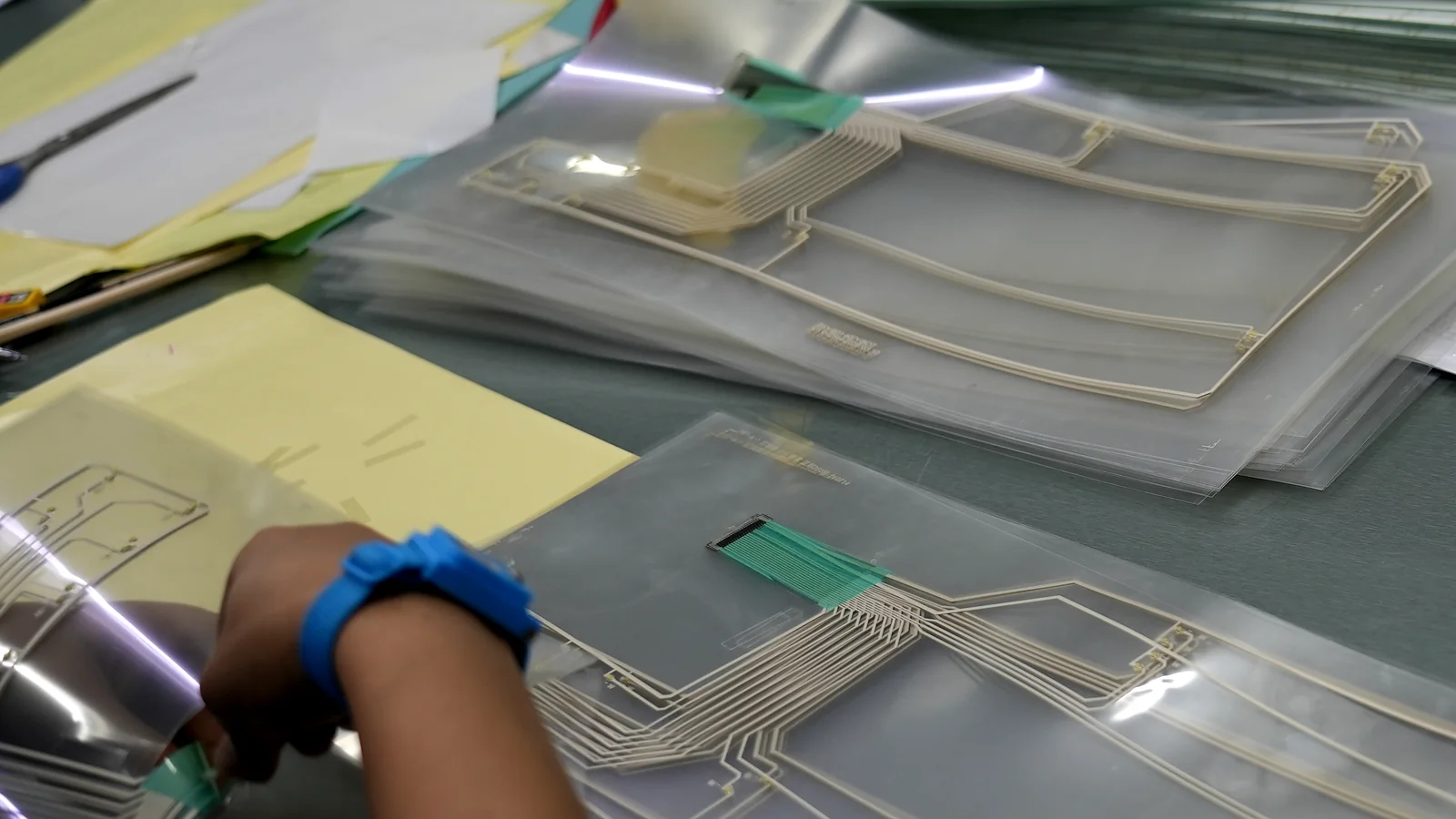
1. Why One HMI Can Require Several Different Adhesives
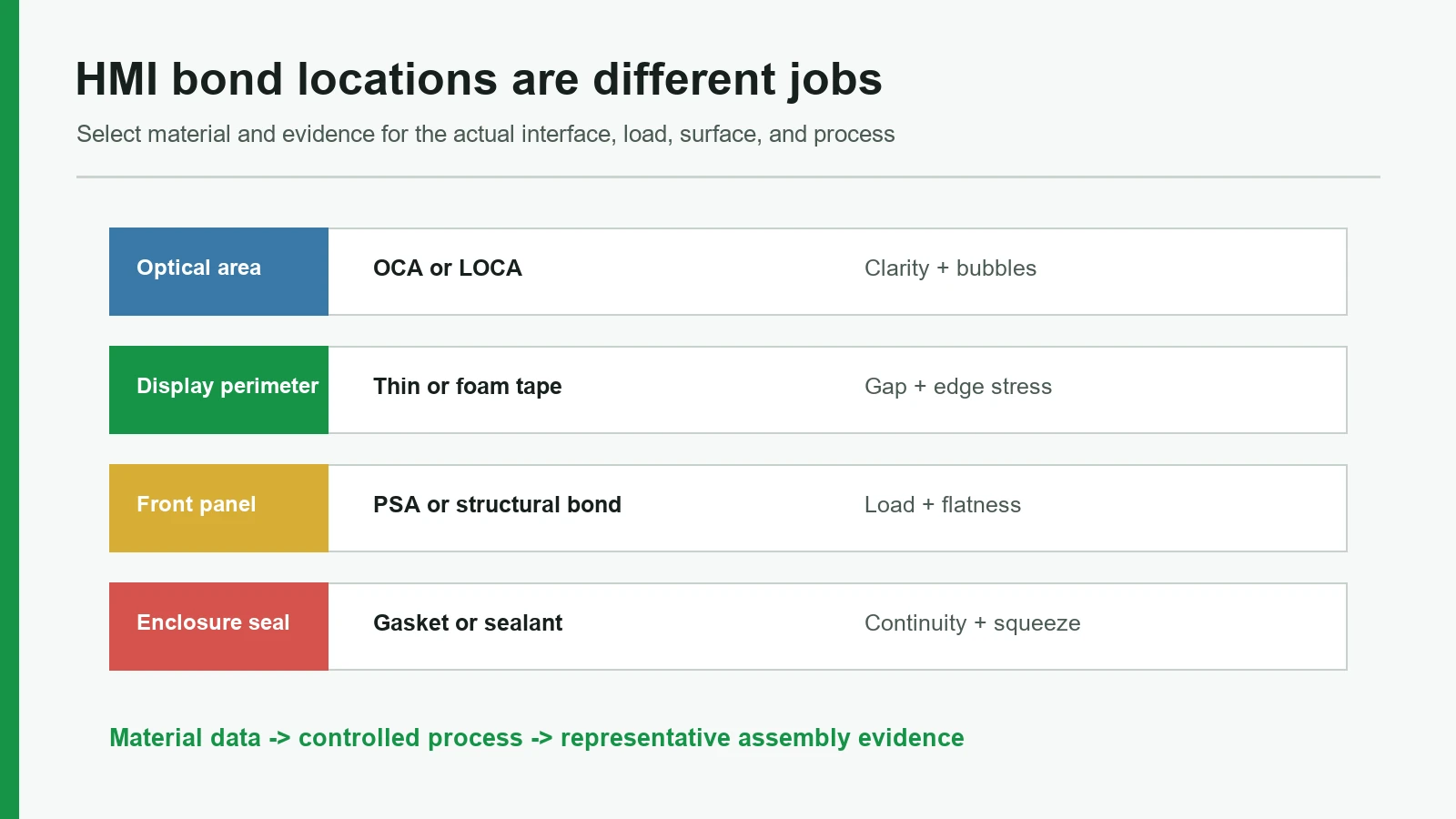
An HMI assembly rarely has one generic “glue joint.” The interfaces are not interchangeable. It may contain an optical laminate, a display perimeter bond, a bezel-to-front-panel bond, a graphic-overlay adhesive, a gasket, and functional tapes for grounding, shielding, or heat transfer. Those interfaces carry different loads and fail for different reasons. Treating them as one material-selection problem is the first design error.
The phrase HMI panel bonding in this guide means bonding within an operator-interface stack. It does not mean automotive body-panel repair. A typical front-panel HMI assembly may look like this, although a real design can omit layers or change their order:
Operator side
Cover lens or graphic overlay
OCA/LOCA if full optical lamination is required
Touch sensor (optional)
OCA/LOCA, engineered air gap, or supplier-defined layer
Display module (optional)
DISPLAY PERIMETER ADHESIVE outside the active area
Bezel or front panel
FRONT PANEL ASSEMBLY ADHESIVE, gasket, or retention
Equipment enclosure
Equipment side
Full-area optical bonding and structural perimeter mounting are separate functions. 3M's display material map places optically clear adhesive, thin bonding tape, foam tape, and liquid adhesive at different interfaces; its published product examples also span very different thicknesses and processes. That supplier-specific map is useful because it exposes the categories, not because every HMI should use a 3M product. 3M's automotive display brochure lists thin tapes, foam tapes, liquid adhesives, and OCA as distinct solution families. Display-integrated HMI assemblies therefore need each bond line labeled before materials are shortlisted. The HMI cover-lens perimeter and optical bonding guide owns the deeper air-gap, perimeter, and full-area optical-bonding comparison.
The evidence chain also has three levels:
| Evidence level | Required content | Boundary |
|---|---|---|
| Material evidence | Current technical data sheet for a named product, construction, thickness, and liner | Does not prove the production process or finished HMI |
| Process evidence | Actual preparation, pressure or dispense, temperature, dwell or cure, equipment, and inspection results | Does not prove performance beyond the tested geometry and conditions |
| Assembly evidence | Representative HMI tested under specified environmental and functional loads | Applies only to the documented configuration, tolerances, process, and acceptance plan |
A result at one level cannot prove the next. Pressure-sensitive-tape peel measurements may not provide design information because backing stiffness, adhesive rheology, and test configuration affect the result. ASTM D3330/D3330M is useful for controlled comparisons and quality checks, not for converting a catalog peel value into field life.
A practical failure chain
| Observed symptom | Likely mechanism to investigate | Evidence to collect | Typical corrective direction |
|---|---|---|---|
| Clean adhesive releases from one surface | Poor wet-out, contamination, wrong chemistry, or unstable treatment | Surface state, contact-angle or wetting-control data, cleaning record, failure face | Change surface preparation or adhesive family; retest the production finish |
| Adhesive splits within its thickness | Cohesive overload, creep, temperature softening, or incomplete cure | Load history, bond-line thickness, cure record, aged failure mode | Change modulus/thickness/chemistry or reduce sustained load |
| Edge lifts first | Peel or cleavage from curvature, rebound, CTE mismatch, or inadequate land | Flatness map, curvature, thermal profile, edge stress, anti-lifting result | Redesign geometry, add compliance, widen or relocate the bond, or add retention |
| Bubbles appear in the optical path | Trapped contamination, poor lamination, outgassing, ink-step mismatch, or cure issue | Bubble timing/location, material lot, lamination pressure, ageing condition | Select an optical system for the actual stack and validate its process |
| Water enters despite good coupon adhesion | Discontinuous perimeter, seam/start-stop defect, tolerance gap, vent/connector path, or enclosure distortion | Complete-enclosure leak path and production cross-section | Correct the enclosure and seal design; repeat the specified ingress test |
Failure mode matters as much as peak force. ISO 10365 provides designations for adhesive, cohesive, and adherend failure patterns, while 3M's joint-stress guidance explains why peel and cleavage concentrate load at an edge. Record both. A single force value without the failed surface is an incomplete result. ISO 10365:2022 and 3M's adhesive-joint stress guide provide the relevant vocabulary.
2. How to Select an Industrial Adhesive for HMI Assemblies: A 10-Point Framework
The selection sequence is interface, surface, wet-out, geometry, load, environment, functional constraints, production, service, and evidence. The order matters. Keeping that order prevents a familiar mistake: choosing a convenient tape or liquid first, then forcing the drawing and test plan to justify it.
2.1 Define the bond location and its job
Name the interface first. Start by identifying both adherends and the adhesive's primary function. “Bond display” is not enough. Specify, for example, printed glass cover lens → capacitive sensor, full-area optical lamination or display carrier → powder-coated aluminum bezel, perimeter mounting and light blocking. A bond that transfers load is not automatically a qualified environmental seal; an OCA that clears the optical path is not automatically a frame adhesive.
3M's technical guidance says the tape-versus-liquid decision depends on the dimensional gap, available equipment, and design challenge. Tapes suit controlled two-dimensional gaps and defined shapes; liquids can address geometries that a flat die-cut cannot. 3M's eBonding technical resources support that screening distinction.
| Interface ID | Example adherends | Primary function | Shortcut to reject |
|---|---|---|---|
| OPT-1 | Printed cover lens → touch sensor | Full-area optical lamination | Calling any clear adhesive an approved OCA |
| PER-1 | Display carrier → bezel | Perimeter mounting, defined compliance, optional light blocking | Treating OCA data as structural-perimeter evidence |
| FP-1 | Front panel → equipment enclosure | Panel mounting and, where specified, contribution to sealing | Claiming enclosure IP from tape data alone |
| FUN-1 | Conductive shield → grounding land | Electrical continuity under specified compression/environment | Assuming conductivity proves primary structural retention |
The drawing assigns a unique identifier, two actual surfaces, primary function, secondary functions, and inspection method to every bond line.
One adhesive specification is copied across the optical path, frame, overlay, gasket, and grounding interfaces without separate requirements.
2.2 Identify the finished surfaces, not just the bulk materials
Adhesive contacts the top few molecular layers of a surface, not the material name in the bill of materials. PC, glass, or aluminum can hide an anti-fingerprint coating, hard coat, black ink, conversion coating, paint, powder coat, release-agent residue, texture, or migrated additive. Two molded PP lots can also arrive with different contamination histories.
The 3M ASPEC method treats substrate condition—surface energy, texture, roughness, and cleanliness—as a core selection input. Its TDS portfolio illustrates why: 200MP products are positioned for metals and high-surface-energy plastics, while 300LSE products are positioned for many low-surface-energy plastics and powder coatings. Those are product-family examples, not a rule that every paint accepts 300LSE. 3M ASPEC and the 3M 9472LE/300LSE TDS both require the exact surface to remain in scope.
Qualification coupons use production coatings, inks, molded resin lots, texture, cleaning, and ageing—not polished laboratory stand-ins.
The adhesive approval reads only “plastic to metal,” with no resin grade, coating code, surface side, or incoming-condition limit.
2.3 Match chemistry to surface energy and control wet-out
An adhesive must make intimate contact before molecular attraction can build. 3M classifies surfaces below roughly 36 dynes/cm as low surface energy; PP, PE, and PTFE are common examples. Glass and many metals wet more readily, but contamination or a coating can make the real interface behave differently. The 36 dynes/cm figure is a supplier classification reference, not a universal adhesion threshold. 3M's surface-energy guide explains the categories.
Cleaning and treatment must be compatible with every visible and hidden layer; tesa's processing guide calls for clean, dry surfaces and warns about oils, waxes, plasticizers, release agents, condensation, and solvent compatibility. Activation by corona, flame, or plasma can decay, which makes the delay between treatment and lamination a process variable; tesa's Professional Bonding processing instructions are general guidance; the selected product and substrate suppliers still control the recipe.
The control plan fixes surface state, cleaner, wipe method, treatment level, maximum treatment-to-bond time, and verification method.
“Wipe with IPA” or “plasma treat” appears as a universal instruction without checking PC, PMMA, ink, AR/AF coating, paint, or primer compatibility.
2.4 Design edge width, flatness, gap, and bond-line thickness together
There is no defensible universal minimum width for a display perimeter adhesive. Width alone proves nothing. Required land depends on the named material, load, stiffness, curvature, gap profile, tolerance stack, sealing path, and process capability. A nominal CAD width is not the minimum manufactured width after die-cut, placement, enclosure, and bezel tolerances accumulate.
Supplier examples show the scale without creating a rule; tesa publishes an automated NarrowSeal display-closing system that can lay a cited product down to 2 mm. 3M's automotive display brochure lists product-family thicknesses from roughly 0.05 mm thin tapes through foam constructions above 1 mm. Both numbers belong to the cited products and processes. Neither proves that a 2 mm land or a particular thickness will carry another HMI. See tesa NarrowSeal and the 3M display-bonding map.
The front-panel HMI tolerance-stack and datum guide extends this geometry problem into datum selection, manufactured land, and worst-case alignment.
The released drawing gives minimum effective land after tolerance, flatness, maximum gap/step, nominal compressed thickness, keep-outs, seam geometry, and compression stops where needed.
The supplier receives only an outer outline and nominal tape width; local steps, ribs, ink ledges, screw distortion, and worst-case gap are missing.
2.5 Keep long-term load out of peel and cleavage
Adhesive joints tolerate distributed shear, tension, and compression more effectively than edge-concentrated peel or cleavage. Curved cover lenses, bowed plastic bezels, cable rebound, screw torque, and mismatched thermal expansion can turn a nominal shear joint into persistent edge peel. A high room-temperature peel number does not remove that mechanism.
3M's joint-design guide defines shear as load spread across the bond area and peel or cleavage as load concentrated at an edge. Henkel's automotive-display guidance separately flags dissimilar-material CTE and the need to balance flexibility with strength in narrow frames. These principles support a geometry review before a product comparison. See 3M's stress guide and Henkel's display structural-bonding guidance.
The load case includes dead load, button force, cable force, enclosure flex, thermal movement, shock, vibration, and assembly preload; the design reduces exposed peel edges.
A flat coupon passes while the production lens must be forced into curvature and remains clamped by adhesive rebound for its entire service life.
2.6 Convert the service environment into bounded test inputs
“Industrial environment” is not a test condition. Conditions need numbers. The adhesive screen needs the operating and storage temperature limits, transition rate, dwell, humidity or condensation state, cleaning fluids and concentrations, immersion or splash duration, UV exposure, shock, vibration, and time under sustained load. It also needs the HMI's powered state and the functions monitored during and after exposure.
IEC 60068-2-14:2023 covers specified changes of temperature, while IEC 60068-2-78:2025 covers high humidity at constant temperature without condensation. They address different mechanisms. IEC 60068-2-6 and IEC 60068-2-27 provide sinusoidal-vibration and shock methods when the equipment environment makes those loads relevant. None of these documents supplies a universal HMI severity. The project specification still selects temperatures, dwell, cycles, mounting, axes, pulses, duration, and acceptance criteria. See the official IEC scopes for temperature change, damp heat, vibration, and shock.
Each environmental row names a condition, specimen state, duration or cycle profile, functional monitoring, inspection, and acceptance criterion.
A supplier's “85/85,” “automotive grade,” “chemical resistant,” or “outdoor” label is accepted without the specimen construction, method, result, and failure threshold.
2.7 Separate structural, optical, electrical, thermal, and light-control functions
A material can perform more than one function, but each function needs its own evidence. OCA or LOCA in the active optical path must be evaluated for the actual cover material, sensor, display technology, ink step, outgassing, bubbles, haze, and ageing. Conductive tape used for grounding needs stable electrical contact under the stack's compression and environment. A thermally conductive adhesive must still satisfy electrical isolation or conductivity requirements. Black perimeter tape may control light leakage without carrying the full structural load.
The tesa HMI OCA guide treats cover material, display technology, thickness, gap filling, outgassing, and UV/light management as separate selection dimensions. 3M likewise maps OCA, structural bonding, EMI, thermal management, and damping to distinct locations in a display assembly. See the tesa automotive HMI OCA guide and 3M information-display solutions.
The specification assigns optical, electrical, thermal, sealing, light-blocking, and structural acceptance tests to the relevant material or assembled interface.
“Optically clear” is treated as proof of touch-sensor compatibility, or conductive/thermal performance is assumed to prove mechanical retention.
2.8 Establish the production window before approving the material
Pressure-sensitive tape offers immediate tack and often immediate handling strength, but wet-out still changes with pressure, temperature, time, and surface state. Tack is not cure. Liquid adhesive introduces dispense volume, bead shape, open time, fixturing, cure access, cure temperature, and full-cure verification. A line that cannot hold those variables will not reproduce a laboratory coupon.
Product-specific data show why generic instructions fail. Nitto's D5331 membrane-switch tape is 0.070 mm thick and lists 15–40°C lamination plus 10–15 N/cm² application pressure; the TDS labels its values typical and not for specification. 3M's electronics guidance uses about 15 psi (approximately 100 kPa) and up to 72 hours as examples for its PSA systems. Henkel's HHD 3597 TDS, by contrast, describes a reactive PUR hot melt with a 90–110°C application range and a moisture-dependent final cure. These are three different processes, not three interchangeable settings. Sources: Nitto D5331 TDS, 3M electronics guidance, and Henkel HHD 3597 TDS.
The work instruction controls incoming storage, cleaning, treatment, application temperature, force/pressure, speed, open time, clamp/fixture, dwell or cure, release-liner removal, and inspection.
“Apply firm pressure” or “allow to cure” appears without a measurable range, timestamp, equipment setting, or lot traceability.
2.9 Design rework and field service into the stack
Reworkability is a construction, not an adjective. The engineer must decide which component should survive removal, where a tool or release trigger can reach, what temperature or chemical exposure neighboring parts tolerate, how residue will be handled, and whether a replacement bond can use the same surface.
Lohmann lists controlled-release mechanisms that include tearing, temperature, solvent, electricity, cutting, stretching, and radiation. 3M describes heat debonding, chemical release, and stretch release as different rework routes. Those options prove that release architecture must be selected; they do not prove that ordinary double-sided tape is repairable. See Lohmann's debonding taxonomy and 3M's electronics rework guidance.
A controlled removal trial defines the protected component, trigger, access path, maximum temperature/force, residue limit, cleaning, replacement procedure, and post-repair function test.
The program requests both maximum permanent holding strength and easy nondestructive removal after years of ageing, but no dedicated debonding product or process is specified.
2.10 Approve evidence, failure mode, and change control—not a data-sheet headline
Final approval should name the product, revision, construction, liner, thickness, supplier site or traceable grade, shelf/storage conditions, production process, and representative test results. A headline is not evidence. A supplier's typical peel or lap-shear value can screen candidates. It cannot become the HMI's design allowable or service-life claim.
ISO 29862:2024 defines several 180° peel methods for self-adhesive tapes. Peel results may not provide design information. ISO 4587:2003 defines rigid-to-rigid lap-shear testing; the procedure does not provide design information. Together, they support disciplined comparison while blocking a common shortcut: ranking unlike adhesives by one catalog number. See ISO 29862:2024, ASTM D3330/D3330M, and ISO 4587:2003.
Approval includes actual-surface results, conditioned results, failure modes, assembly tests, a frozen process window, incoming controls, and supplier change-notification requirements.
Procurement can substitute a “similar” chemistry or thickness without requalification because the drawing names only “industrial double-sided tape.”
3. Adhesive-Family Decision Table for HMI Panel Bonding
The best starting family follows the interface and process, not a generic strength ranking. Use this table to reduce the field; a current TDS and representative tests still decide the named product.
| Adhesive family | Best starting use | Process advantage | Main liabilities to control | Not the best choice when | Evidence anchor |
|---|---|---|---|---|---|
| Thin transfer or double-coated film PSA | Graphic overlays, membrane layers, FPCs, thin brackets, or flat perimeter joints with tightly controlled gaps | Precise die-cut geometry, low thickness, clean application, immediate handling | Poor gap bridging, edge peel, substrate texture, low-surface-energy finishes, limited impact absorption | The surface mismatch is deeper than the adhesive can wet or the assembly needs substantial damping | 3M format guidance and Nitto D5331 |
| Double-coated foam or acrylic foam tape | Display/frame mounting where compliance, shock absorption, sealing continuity, or minor tolerance accommodation is needed | Controlled thickness, distributed load, conformability, die-cut or automated placement | Creep under sustained load, compression variation, visible gap, edge stress, difficult permanent removal | The design cannot tolerate foam thickness, requires a very narrow liquid path, or imposes unresolved long-term peel | 3M display map and tesa NarrowSeal |
| Liquid structural or elastic adhesive, including qualified PUR, urethane, silicone, or MS systems | Complex paths, irregular or wider gaps, narrow dispensed beads, curved interfaces, or dissimilar materials needing controlled compliance | Gap filling, three-dimensional path freedom, tunable bead, potential compliance | Dispense variation, bubbles, squeeze-out, open time, fixture load, cure depth, moisture/heat access, inspection, rework | The line cannot control bead volume/cure or sensitive components cannot tolerate the cure and removal conditions | Henkel display guidance and Dow moisture-cure limits |
| OCA, LOCA, or another qualified optical-bonding system | Full-area bonding inside the optical path between compatible lens, sensor, and display layers | Removes the designed air interface and can integrate optical layers | Cleanliness, bubbles, haze, outgassing, ink steps, dielectric/ionic compatibility, lamination or cure equipment, difficult rework | Only perimeter mounting or structural frame attachment is needed, or the optical stack cannot tolerate the process | tesa OCA selection guide |
| Dedicated debondable or removable system | High-value displays, planned repair, production rework, or material recovery with a defined release path | Controlled separation when the construction and trigger are validated | Reliability-versus-release tradeoff, trigger access, neighboring-component limits, residue, replacement process | Removal is not required or the release trigger cannot reach the bond safely | Lohmann debonding on demand |
| Functional conductive, thermal, insulating, or light-blocking tape | EMI grounding, heat transfer, dielectric isolation, or light control at a defined interface | Adds a controlled functional layer in thin form | Functional drift under compression/environment, galvanic or electrical risk, thermal impedance, uncertain structural capacity | The material is expected to carry the main structural or sealing load without separate mechanical evidence | 3M information-display material map |
When the common recommendation is not the best construction
| Common starting idea | It is not the best choice when | Better direction to evaluate |
|---|---|---|
| Perimeter tape | The active display needs full-area optical lamination, or worst-case gap and steps exceed validated conformability | Qualified optical bonding for the active area, or a controlled liquid process for the irregular perimeter |
| Full optical bonding | An engineered air gap meets the optical requirement and low-cost field replacement controls the decision | Documented air-gap/perimeter construction with assembly-level optical and ingress evidence |
| One-part moisture-cure liquid | A deeply enclosed joint lacks verified moisture access and full-cure evidence | A cure route compatible with joint depth, component limits, takt, and inspection |
| Permanent foam tape | Nondestructive screen replacement is contractual | Dedicated debondable construction with a validated access and removal path |
| Adhesive-only retention | Geometry creates unresolved long-term peel, creep, or safety-critical load | Joint redesign and, where required, mechanical retention |
| Thinnest available bond line | The assembly needs compliance, impact absorption, or tolerance accommodation | A validated thickness that balances wet-out, gap, creep, stiffness, and appearance |
4. A Six-Step Buyer and Qualification Process
The sourcing process should eliminate weak assumptions before it eliminates suppliers. The sequence matters here too. These six steps produce a short list that an adhesive supplier, converter, HMI assembler, and OEM quality team can evaluate against the same stack and conditions.
Step 1 — Freeze the stack and label every interface
Create one exploded section through the worst-case region: active display, printed border, sensor tail, perimeter land, bezel rib, fastener, enclosure step, and any gasket. Give each adhesive interface an ID. For each ID, name both production surfaces and state whether the joint carries structural load, seals, fills a gap, controls light, conducts heat/electricity, or enters the optical path.
Do not start with an adhesive part number. Start with geometry and function. This keeps an optical laminate from being evaluated against a structural tape requirement and prevents a front panel assembly adhesive from inheriting an untested sealing claim.
The HMI panel assembly design checklist can serve as the cross-functional drawing-review companion when that route is published.
Step 2 — Write the service envelope and failure criteria
Record minimum and maximum storage and operating temperatures, transition profile, humidity or condensation, washdown or immersion, actual cleaning-fluid names and concentrations, UV exposure, vibration spectrum, shock pulse, button or touch load, cable load, display mass, mounting orientation, and expected repair event. Distinguish continuous, cyclic, and incidental exposure.
Then define failure in observable terms: edge lift, leak, bubble, haze shift, touch error, light leak, bond displacement, cohesive split, coating pull-off, or loss of electrical/thermal function. “No degradation” is not an acceptance criterion until the measurement and allowable change are named.
Step 3 — Screen formats, then named products
Use the decision table to select two or three plausible formats. Request a current TDS, safety data, construction and liner details, storage/shelf requirements, application instructions, test methods, typical-versus-specification labels, and change-notification policy for each named product. Confirm that the exact thickness and converter construction are commercially available.
Treat supplier examples as directional. A product positioned for PP or powder coat still needs the actual molded or coated part. An OCA positioned for PMMA still needs the ink, sensor, display, and lamination process. Reject any proposal that identifies only a chemistry—such as “acrylic foam” or “PUR”—without a traceable grade and process.
Step 4 — Test actual surfaces and record how they fail
Build screening coupons from production-intent adherends, coatings, ink, texture, treatment, and cleaning. Control application pressure or bead geometry, dwell/cure, conditioning, peel angle or load direction, and test rate. Use a recognized method where it fits, but preserve the real surface rather than substituting standard steel for the only decision.
ISO 29862 and ASTM D3330 can structure PSA peel comparisons; ISO 4587 can structure rigid lap-shear comparisons. Their own scopes and cautions block direct conversion into design allowables. Record whether each specimen shows adhesive failure, cohesive failure, or adherend/coating failure under the ISO 10365 vocabulary. A strong result that tears a weak paint layer may disqualify the surface system rather than approve the adhesive.
Step 5 — Build representative assemblies and establish the process window
Coupons cannot reproduce lens bow, housing flex, a sensor tail, screw torque, a perimeter seam, an ink step, or a trapped cure path. Build production-intent subassemblies at nominal and tolerance-limit conditions. Challenge low and high application pressure, minimum and maximum application temperature, placement error, gap, bead volume, dwell/cure, and fixture release time.
Inspect cross-sections or other appropriate evidence at starts, stops, corners, steps, and narrow lands. The objective is not a single golden sample; it is a stable window the line can hold. The related membrane switch lamination and HMI assembly capability page provides manufacturing context, while the qualification still belongs to the named project.
Step 6 — Validate the complete assembly and release controlled documents
Run environmental and functional tests on the representative HMI and, where sealing is claimed, on the finished enclosure configuration. Monitor display, touch, switch, optical, electrical, and mechanical functions that the bond can affect. Inspect immediately after exposure and again after any defined recovery period; viscoelastic response can make timing relevant.
Release the drawing, approved-material list, work instruction, inspection plan, validation report, and supplier/converter change controls together. The testing and validation planning page is a natural handoff for discussing evidence, not proof that an unspecified stack has passed. Any material, coating, ink, tool, liner, thickness, treatment, or process change that can alter the interface needs a defined review and requalification trigger.
5. Project Validation Matrix and Drawing Checklist
A defensible test plan links each service condition to the smallest useful specimen, then confirms the final assembly. Methods do not set limits. IEC, ISO, and ASTM describe repeatable test approaches, while the OEM program defines severity and acceptance.
For sensor-specific drift, false-touch, dielectric, and post-ageing checks, the capacitive-touch HMI reliability validation guide owns the deeper workflow.
Validation matrix
initial planning values — confirm before release
ISO, IEC, and ASTM methods define repeatable test approaches; they do not supply a default adhesive, process window, severity, or pass limit for an HMI. That is why this temporary block uses traceable supplier data and keeps the original material, substrate, conditioning, and method boundary visible.
| ID | initial value | Intended planning use | Source boundary and required replacement |
|---|---|---|---|
| PV-01 | 150 kPa (15 N/cm²) at 23°C; candidate application range 15–40°C | Initial acrylic-PSA lamination trial | This upper-middle planning point sits at the high end of Nitto D5331's 10–15 N/cm² range; compare 3M VHB 5952 and tesa's processing guide. Replace it with pressure at the adhesive layer, equipment limits, actual-surface evidence, and the approved product's instructions. It does not apply to OCA lamination, conductive adhesives, or reactive liquids. |
| PV-02 | 72 h at 23°C before the final comparative measurement | Conditioning point for an acrylic-PSA screen | 3M publishes a 72-hour room-temperature strength-build example for VHB 5952. Replace this value with the selected PSA's documented build curve and the project's handling, test, and shipment-release rules. It is not a universal cure time. |
| PV-03 | 0.13 mm; 12.3 N/cm 90° peel on polycarbonate | Thin high-surface-energy interface reference | The 3M 468MP data use PC, 23°C, 72 h dwell, ASTM D3330, a 90° geometry, about 300 mm/min, and an aluminum-foil backing. Replace the material, surface preparation, backing, rate, result distribution, failure mode, and acceptance rule. Do not transfer 12.3 N/cm to glass, ink, PMMA, ABS, or a finished HMI. |
| PV-04 | 0.132 mm; 14.9 N/cm 90° peel on polypropylene | Separate low-surface-energy interface reference | The 3M 9472LE data use a named PP surface, 23°C, 72 h dwell, ASTM D3330, a 90° geometry, about 300 mm/min, and a 2 mil aluminum-foil backing. Replace this with the actual molded grade, texture, release-agent state, treatment, lot spread, failure mode, and approved minimum. |
| PV-05 | 1.1 mm; 39 N/cm peel and 550 kPa overlap shear | Thick structural-foam comparison point for a rigid, nominally flat front-panel joint | These are 3M VHB 5952 supplier values under its cited stainless-steel, backing, conditioning, ASTM D3330, and ASTM D1002/ISO 4587 conditions. Replace them with the actual joint thickness and assembly evidence. Neither force value is an HMI design allowable. |
| PV-06 | 250 µm OCA | Optical-stack space claim for a first prototype | The an OCA family spanning 50–500 µm. Replace 250 µm after measuring the real ink step, gap, flatness, outgassing, dielectric needs, display technology, and lamination capability. OCA thickness is not a perimeter-mounting specification. |
| PV-07 | 105°C for at least 1,000 h; 85°C/85% RH for at least 1,000 h | Upper-tier supplier exposure references for an automotive OCA short list | tesa publishes these as supplier-family screening statements, but the public guide does not disclose the complete method, specimen, pass criterion, or numeric result. Replace both with the OEM profile, named method, specimen, sample size, monitoring, recovery, acceptance criteria, and verified results. Do not claim JASPER passed them. |
| PV-08 | 95°C static shear for at least 1,000 h | Upper-tier supplier exposure reference for display-mounting tape | The same tesa guide publishes this frame-tape reference without a public load, bonded area, displacement limit, or full method. Replace every missing parameter and the measured result before using it as a qualification claim. Test hours do not equal field life. |
Accelerated exposure is not a field-life conversion. No direct general relationship exists between laboratory ageing and bonded-assembly service life. Test hours can support a specified comparison; they do not become years without a validated correlation. See ISO 9142:2003.
Drawing and RFQ input checklist
Provide this information before requesting an adhesive recommendation:
| Input group | Required project information |
|---|---|
| Stack and surfaces | Exploded stack; section through the worst-case region; both adherends; resin/metal/glass grade and supplier; coating, paint, powder coat, hard coat, ink, primer, texture, treatment, and bonding side |
| Geometry and keep-outs | Minimum effective land after all tolerances; flatness; curvature; steps; maximum gap; nominal bond-line thickness; compression limit; active-area, optical, electrical, thermal, light-blocking, and cosmetic keep-outs |
| Loads and environment | Display mass, cable and button force, screw distortion, shock, vibration, storage/operating temperature profiles, transition rate, humidity/condensation, UV, fluids, and cleaning method |
| Production process | Application equipment, surface preparation, pressure or bead-volume control, open time, dwell/cure, fixture, takt, visual/dimensional inspection, and bond-line inspection |
| Validation and service | Functional and leak methods; rework target; protected component; access path; release method; residue limit; replacement process; regulatory, customer, industry, and enclosure-level requirements |
| Supply and change control | Volume/configuration mix when it affects conversion or automation; approved material; lot traceability; shelf/storage controls; deviations; supplier/converter change notification |
6. Release Blockers That Disqualify an Adhesive Proposal
These release blockers override a persuasive catalog or low piece price because each one leaves a known failure mechanism uncontrolled.
- The product is selected before the two finished surfaces are identified. Chemistry cannot compensate for an unknown coating, ink, release agent, or treatment.
- A catalog peel value on steel is presented as field-life proof. ASTM D3330 explicitly limits that inference.
- The proposal calls a tape or sealant “IP67.” IEC 60529 classifies the tested enclosure; seams, fasteners, vents, connectors, distortion, and tolerances remain in scope.
- Nominal perimeter width is shown without minimum effective land. Die-cut, placement, bezel, and enclosure tolerances can erase the apparent margin.
- OCA, perimeter mounting, and enclosure sealing are treated as one function. They occupy different interfaces and need different evidence.
- The work instruction says only “clean and press” or “dispense and cure.” A measurable process window is missing.
- Immediate tack or handling strength is called full cure. PSA wet-out and reactive-liquid cure follow different time, temperature, pressure, and moisture mechanisms.
- A flat coupon is the only test for a curved or tolerance-loaded stack. Rebound, CTE, cable force, and screw distortion are absent.
- The test report records peak force but not the failed surface. Adhesive, cohesive, coating, and adherend failure lead to different corrective actions.
- A permanent product is promised to be nondestructively reworkable without a release path. Repairability needs a dedicated construction and validated removal process.
7. Frequently Asked Questions
What is the best industrial adhesive for HMI assemblies?
There is no universal best industrial adhesive for HMI assemblies. The correct short list follows the bond location, finished substrates and coatings, minimum land, gap and flatness, load mode, environment, production process, and repair requirement. A named product should be approved only after actual-surface coupons, representative assemblies, and the applicable enclosure or functional tests pass.
What is the difference between display perimeter adhesive and OCA or LOCA?
Display perimeter adhesive mounts or seals around the display's edge, normally outside the active optical area. OCA or LOCA bonds across an optical interface between compatible cover-lens, touch-sensor, or display layers. They solve different problems. Optical materials need clarity, bubble, outgassing, ink-step, dielectric, and lamination evidence; perimeter materials need structural, geometry, process, and sealing evidence.
How wide should a display perimeter adhesive be?
The required width must be calculated and tested for the named adhesive, minimum manufactured land, joint geometry, loads, stiffness, curvature, gaps, and environmental exposure. There is no universal minimum. A supplier's 2 mm product example proves only that its specified material and automation process can create that path; it does not qualify a 2 mm bond in another HMI.
Can foam tape make an HMI enclosure IP65 or IP67?
Foam tape can contribute to a continuous perimeter seal, but it cannot establish an IP65 or IP67 rating by itself. IEC 60529 assigns the classification to the tested enclosure configuration. The production seal path, corners, starts and stops, fasteners, vents, connectors, distortion, surface condition, and assembly tolerances must all be represented in the enclosure-level test.
How do you bond an HMI panel to polypropylene or powder coating?
First identify and test the actual PP grade or powder-coat system, including texture, additives, release agents, cure, contamination, and ageing. Then screen an adhesive formulated for that surface-energy range or a compatible pretreatment. 3M's 300LSE family is one product example for many LSE plastics and powder coatings, not proof that every PP or coating will bond without primer or treatment.
How much pressure and dwell time does a PSA need?
Use the selected product's current TDS and a validated production window. Pressure, application temperature, dwell, adhesive firmness, surface energy, and roughness all affect wet-out. Supplier examples vary: Nitto D5331 lists 10–15 N/cm² at 15–40°C, while 3M electronics guidance uses about 15 psi and up to 72 hours for some PSA systems. Neither range is universal.
Is higher peel strength always better for HMI panel bonding?
No. Peel measurements may not provide design information, and unlike tapes can respond differently because backing stiffness and adhesive rheology change the test. HMI panel bonding can fail through sustained shear, creep, cleavage, curvature, temperature, moisture, coating release, or process variation. Compare candidates on the actual surfaces and record failure mode, not just peak peel force.
How should an HMI adhesive be tested for heat, humidity, vibration, and chemicals?
Translate the real service profile into a project matrix, then test coupons, representative subassemblies, and the finished HMI at the appropriate level. IEC 60068 methods can structure temperature-change, steady damp-heat, vibration, and shock tests, but the OEM must define severity and acceptance. Use actual cleaners and fluids, monitor affected functions, and avoid converting accelerated hours directly into field years.
When should a front panel assembly adhesive be reworkable?
Specify reworkability when a high-value display, sensor, lens, or frame must survive production repair, field service, or end-of-life separation. Define the protected part, release trigger, tool access, maximum heat or force, residue limit, cleaning, replacement bond, and post-repair test. Standard permanent double-sided tape should not be called reworkable without a demonstrated removal process.
8. What to Send Before Adhesive Selection Starts
Share the substrate stack and service conditions before requesting a material recommendation: the section drawing, actual surface and coating codes, minimum land, flatness and gap, optical/electrical/thermal functions, temperature and humidity profiles, fluids and cleaning, shock/vibration loads, assembly pressure or dispense constraints, takt time, and rework target. That package lets the material supplier and assembler discuss a testable interface instead of a generic “strong adhesive.”
For a narrower overlay or membrane-switch mounting decision, see the related membrane switch adhesive selection guide. The HMI front panel assembly manufacturing case provides related application context; its project details should not be treated as universal adhesive specifications.
Technical References
- Source: 3M's automotive display brochure. Accessed 2026.
- Source: ASTM D3330/D3330M. Accessed 2026.
- Source: ISO 10365:2022. Accessed 2026.
- Source: 3M 9472LE/300LSE TDS. Accessed 2026.
- Source: tesa's Professional Bonding processing instructions. Accessed 2026.
- Source: tesa NarrowSeal. Accessed 2026.
- Source: 3M display-bonding map. Accessed 2026.
- Source: Henkel's display structural-bonding guidance. Accessed 2026.
- Source: temperature change. Accessed 2026.
- Source: damp heat. Accessed 2026.
- Source: vibration. Accessed 2026.
- Source: shock. Accessed 2026.
- Source: tesa automotive HMI OCA guide. Accessed 2026.
- Source: Nitto D5331 TDS. Accessed 2026.
- Source: Henkel HHD 3597 TDS. Accessed 2026.
- Source: Lohmann's debonding taxonomy. Accessed 2026.
- Source: ISO 29862:2024. Accessed 2026.
- Source: ISO 4587:2003. Accessed 2026.
- Source: Nitto D5331. Accessed 2026.
- Source: 3M display map. Accessed 2026.
- Source: Henkel display guidance. Accessed 2026.
- Source: Dow moisture-cure limits. Accessed 2026.
- Source: tesa OCA selection guide. Accessed 2026.
- Source: Lohmann debonding on demand. Accessed 2026.
- Source: IEC 60068-2-14:2023. Accessed 2026.
- Source: IEC 60068-2-78:2025. Accessed 2026.
- Source: IEC 60068-2-6. Accessed 2026.
- Source: IEC 60068-2-27. Accessed 2026.
Review the complete HMI assembly before design release
Send the front-panel drawing, stack, display, circuit, connector, enclosure, service conditions, and acceptance plan for review.