
HMI optical bonding is the stronger choice when internal reflection, parallax, or contamination inside the viewing gap prevents an HMI from meeting a defined use condition. An HMI cover lens air gap or perimeter bond is usually better when display replacement, mechanical isolation, lower process complexity, or supply flexibility matters more. This guide compares both routes for OEM display, touch, cover-lens, enclosure, and service decisions.
1. HMI Optical Bonding or Air Gap: Quick Verdict
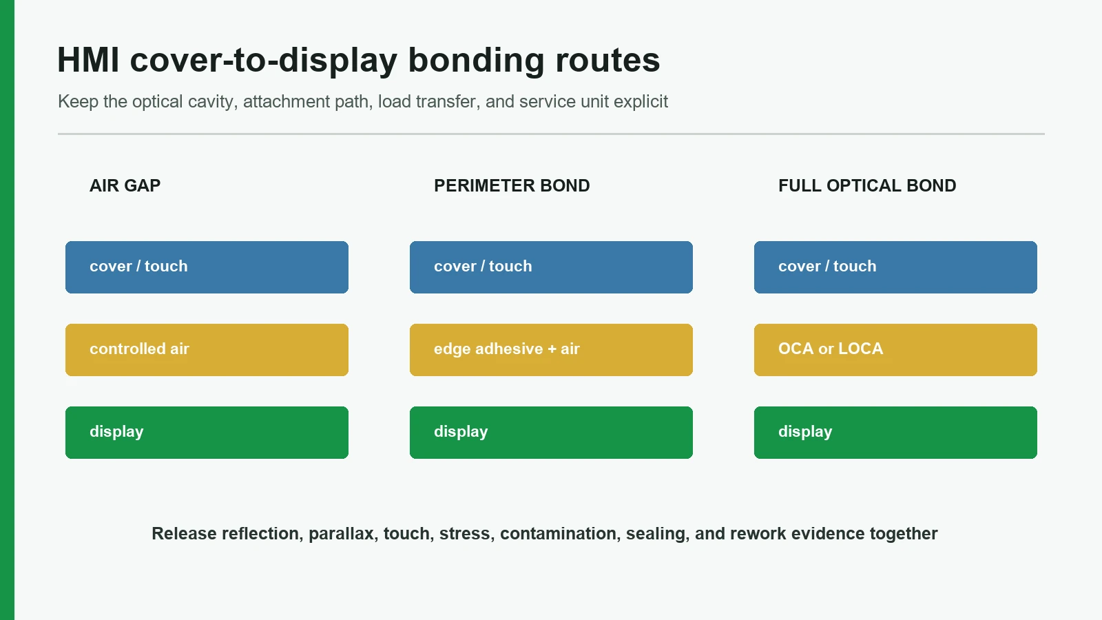
No construction wins every HMI program. First decide whether the viewing area contains air. Then decide whether that cavity is intentional, edge-attached, or fully filled with optically clear material.
| Construction | What occupies the viewing area | Choose it when | Do not choose it when |
|---|---|---|---|
| Intentional air gap | Controlled air space between cover/touch layer and display | The display must remain removable; ambient light is controlled; mechanical isolation has priority | Reflection, parallax, cavity dust, or condensation fails the use requirement |
| HMI perimeter adhesive or gasket | Air remains in the window; an edge frame locates or seals the parts | A narrow attachment path, defined cavity, and possible disassembly fit the enclosure | The team expects edge adhesive to remove optical air interfaces |
| OCA film | Preformed optically clear adhesive fills the designed interface | Flat geometry, controlled print steps, repeatable lamination, and a qualified adhesive grade are available | The stack has uncontrolled bow, incompatible plastics/coatings, or steps the selected film cannot wet |
| LOCA/OCR liquid | Dispensed optical liquid fills the interface and is cured in place | Flow must fill a shaped or variable gap and the supplier defines dispense, containment, cure, and rework | Cure access, shadowed borders, overflow control, or display exposure limits remain unresolved |
Use a full-surface bond only after the optical gain is proven against its mechanical and service costs. A bonded sample that looks clear at room temperature does not establish hot/cold image uniformity, touch behavior, enclosure sealing, or field repair.
For a project-specific stack, the display-window HMI assembly review should start with the exact cover drawing, display model and revision, touch-sensor construction, enclosure section, viewing condition, and replaceable-unit plan. That link defines an integration route; it is not evidence of a particular JASPER adhesive or bonding process.
2. Define the Cover–Touch–Display Stack Before Selecting Adhesive
Display optical bonding means replacing a designed air interface across the viewing area with transparent bonding material. Full optical bonding fills the gap between the LCD and the cover glass or touchscreen. Perimeter bonding is different: adhesive or gasket surrounds the window while air remains above the display.
Draw every optical and mechanical layer instead of reducing the assembly to “glass plus LCD.”
operator and ambient light
outer texture or anti-glare / anti-reflective treatment
glass or acrylic cover lens
second-surface print, black mask, clear window, ink step
optional projected-capacitive touch sensor and its adhesive
intentional air gap, perimeter cavity, OCA film, or LOCA/OCR
display polarizer, active area, view area, and module frame
support frame, foam/gasket, fasteners, PCB, and enclosure
Three interfaces need separate answers. Keep them separate. Ambiguity here is expensive.
- Is the cover lens bonded to a separate touch sensor?
- Is the cover or touch sensor bonded across the display’s viewing area?
- Is the front stack attached to the enclosure with an HMI perimeter adhesive, gasket, bezel, or fasteners?
A project can answer “yes,” “no,” and “yes” in that order. Calling the complete front “optically bonded” without naming the two bonded surfaces hides process ownership, service boundaries, and likely failure locations.
Overlay material, adhesive, transition layers, air gaps, moisture, display proximity, sensor geometry, and controller behavior interact. That relationship is why a touch controller tuned before final bonding may need verification after the display, ground path, cover, and enclosure are installed. The related capacitive touch panel design guide can hold the electrode, tail, controller, and tuning detail; this article owns the display-side interface decision.
3. What the Air Interface Changes Optically
An air gap adds refractive-index transitions at the cover-to-air and air-to-display boundaries. Ambient light reflected at those internal interfaces competes with the displayed image. Filling the internal air gap with transparent material reduces internal reflections and can improve perceived contrast in bright surroundings.
This does not remove reflection from the outside face. Cover texture, anti-glare or anti-reflective treatment, fingerprints, tint, display luminance, mounting angle, and ambient-light direction still affect readability. Compare the complete surface and internal stack under the specified use condition rather than quoting a universal reflection reduction.
Parallax and touch registration
Parallax is the apparent shift between the image plane and the front surface when the display is viewed obliquely. A thicker physical separation generally makes the shift more noticeable. Optical bonding can reduce the designed separation, but it cannot correct a misregistered window, an incorrect coordinate map, a masked display edge, or targets that are too small for the installed viewing cone.
Approve the HMI from the operator’s actual eye positions. Include center, edge, and corner targets; the normal mounting angle; gloves if required; and the finished bezel. A straight-on product photograph is not a parallax test.
Newton rings and near-contact gaps
Newton rings are interference fringes associated with a thin air film whose thickness varies across two optical surfaces. Boston University’s physics reference demonstrates this relationship with a curved surface above a flat surface. In an HMI, moving colored rings can point to local near-contact rather than a properly controlled clearance.
Review cover bow, display flatness, spacer height, gasket compression, bezel pressure, enclosure twist, and temperature. The correction may be a larger controlled gap, a full bond, a different support method, or tighter flatness control. No single spacer thickness prevents fringes in every stack.
Optical decision boundary
Use measured comparisons. Set the test first. Define ambient illuminance or a repeatable site simulation, display content and brightness, viewing angles, surface condition, and pass/fail method. The same display should be evaluated behind the proposed cover in air-gap and bonded forms where practical. Record black level, glare, color shift, image uniformity, window registration, and touch mapping—not just subjective “clarity.”
4. Design an HMI Cover Lens Air Gap and Perimeter Bond as a Cavity
An air-bearing design still needs a controlled cross-section. Specify the cover and display datums, nominal clearance, worst-case flatness and bow, spacer or hard-stop locations, and the conditions under which contact is prohibited. Shock, vibration, enclosure flex, external pressure, and temperature can consume a room-temperature clearance.
An HMI perimeter adhesive or gasket performs several possible jobs: locating the display, supporting the cover, closing a local path, spacing the surfaces, damping motion, or allowing later removal. One material should not be assumed to perform all six. The drawing must show the continuous path, joint positions, corners, display keepouts, compression target, hard stops, vent or seal route, and peel access.
Air cavities also require a moisture strategy. A vented cavity, filtered cavity, nominally sealed cavity, and pressure-equalized cavity behave differently. Filling the display gap removes that specific space as a dust or moisture reservoir. That benefit does not make the whole HMI waterproof. IEC 60529 classifies protection provided by an evaluated enclosure, including its openings, joints, cables, fasteners, and assembly—not an isolated cover lens or adhesive frame.
Choose an intentional gap or perimeter route when:
- the display is a separately replaceable module;
- optical performance passes in the installed ambient-light condition;
- display supplier limits prohibit the proposed lamination, pressure, or cure;
- the cover and display require mechanical isolation;
- a qualified full-bond process is not available for the size and materials;
- display substitutions are likely during the product life; or
- the program cannot support bonded-module spares.
Perimeter bonding is not the best choice when the design depends on eliminating internal reflection, parallax, or contamination in the viewing area. Air remains there.
5. How to Specify HMI Optical Bonding: OCA vs LOCA
OCA and LOCA both fill an optical interface, but they create different manufacturing controls. The adhesive family name is not a production specification. Identify the exact supplier, grade, thickness or dispensed bond line, storage condition, surface preparation, fixture, process recipe, inspection method, rework rule, and approved substrates.
OCA film
Optically clear adhesive film arrives at a defined nominal thickness with release liners. It can suit flat stacks where a converted outline can be aligned and laminated without particles, wrinkles, trapped air, or unfilled topography. It avoids a liquid dispense and in-place liquid cure, but the process still needs controlled cleaning, liner removal, pressure support, alignment, and inspection.
ACO 01N-XXX film options span approximately 50–250 µm for named cover-lens-to-sensor or sensor-to-sensor interfaces. Those values describe that named family, not every display bond. Use the selected grade, ink step, substrate, flatness, display supplier limits, and qualified lamination process to release the bond thickness.
OCA questions for the drawing and process review:
- Can the selected film wet the black-mask or decorative ink step without a visible void?
- Is it approved for the cover, coating, print, touch sensor, ITO surface, polarizer, and operating environment?
- What pressure, temperature, roller or vacuum process, and support does the supplier permit?
- How are liner fragments, particles, bubbles, wrinkles, edge squeeze, and misregistration inspected?
- What storage, conditioning, shelf-life, and lot-traceability controls apply?
- Can the bond be separated without unacceptable polarizer, sensor, coating, print, or cover damage?
LOCA or OCR liquid
Liquid optically clear adhesive or resin is dispensed into the designed interface and cured after alignment. Flow can help fill geometry that is difficult for a flat die-cut film, but it introduces dispense volume, dam or edge containment, overflow, bubble removal, cure access, shrinkage, and cleanup questions. Liquid optical bonding and dry precut bonding require different process controls; liquid display materials also differ in viscosity and rework behavior.
LOCA/OCR questions for process release:
- What viscosity and flow behavior fit the gap, display size, border, and dispense path?
- Can UV or visible light reach every required cure region beneath black masks, frames, flexible circuits, and opaque features?
- How are bond-line thickness, fill front, bubbles, overflow, and contamination measured?
- What fixture supports the display without imposing non-uniform pressure?
- Which cure energy, exposure geometry, post-cure, and verification method does the material supplier require?
- What are the selected grade’s shrinkage, modulus, thermal-expansion, yellowing, and rework boundaries?
Low-shrinkage, air-entrapment, and rework characteristics apply only to named materials such as the 9700 series. They are not universal LOCA guarantees. A surface that feels cured does not prove complete cure through the production stack.
Process selection table
| Question | OCA film | LOCA/OCR liquid |
|---|---|---|
| Incoming form | Die-cut pressure-sensitive film with liners | Dispensed liquid or gel |
| Geometry preference | Flat, controlled interfaces | Variable gaps, shaped interfaces, or designed flow paths |
| Main process risks | Particles, wrinkles, alignment, liner handling, step wet-out | Bubbles, dispense volume, overflow, cure shadows, shrinkage |
| Thickness control | Tied to selected film grade and lamination | Tied to dispense, fixturing, spacers, flow, and cure |
| Plastic-cover issue | Grade-specific PC/PMMA adhesion and outgassing review | Grade-specific chemistry, flow, cure, stress, and surface review |
| Rework | Depends on film, substrate, age, tools, and damage limits | Depends on cured chemistry, cut/separation method, and damage limits |
No table row replaces the adhesive or display supplier’s technical data. Plastic covers, thick ink steps, and curved stacks require grade-level OCA selection.
6. Glass and Acrylic Change the Bonding Decision
A cover lens changes more than appearance. It contributes flatness, stiffness, thermal expansion, surface chemistry, print-step height, edge condition, optical finish, impact behavior, cleaning response, and replacement cost.
A glass nameplate can provide a rigid printed surface, clear display window, and touch graphics. The design still has to state the actual glass type, strengthening condition, edge finish, holes and notches, bow, coatings, print, black mask, bond face, and mounting load. A stiff cover can transfer frame or fixture error into a sensitive display if the load path is wrong.
For acrylic or polycarbonate covers, review grade, manufacturing route, hard coat, moisture and volatile release, creep, thermal expansion, print/coating compatibility, scratch requirement, and fixture support. 817XCL and 826XN are specific OCA families for plastic-cover and outgassing-related requirements. That evidence supports a compatibility review; it does not approve every PMMA sheet, ink, coating, or HMI environment.
Do not select full-surface bonding merely because glass appears flat or acrylic appears light. Evaluate parts after printing, coating, conditioning, mounting, and temperature exposure. The production-intent assembly—not a bare incoming plate—is the relevant geometry.
7. Follow the Load Path to Prevent Display Mura
Mura is visible luminance or color non-uniformity. A full-surface bond mechanically couples the cover, adhesive, touch layer, and display. Non-uniform bond thickness, cure shrinkage, fixture pressure, frame support, gasket compression, fastener load, or thermal expansion can then appear as a bright patch, dark patch, color shift, or pressure mark.
cover bow / print step / bond-line variation
adhesive modulus, cure, and local constraint
display polarizer and cell receive uneven load
frame, gasket, fastener, and enclosure add stress
hot/cold image-uniformity defect in the installed HMI
Control the load path with display-supplier support zones and keepouts, cover and frame flatness, uniform fixture support, bond-line mapping, hard stops, gasket compression, fastener sequence, and installed hot/cold image inspection. Do not use the enclosure to flatten a display by force. Do not use optical adhesive as compensation for uncontrolled frame geometry.
| Symptom | Possible stack cause | First evidence to collect |
|---|---|---|
| Ring or fringe pattern | Thin varying air film, local near-contact, bow | Flatness, spacer, contact, pressure, and temperature map |
| Bubble after conditioning | Particle, incomplete wet-out, trapped gas, plastic outgassing, process drift | Bubble location, material lot, substrate, recipe, and exposure history |
| Edge delamination | Surface preparation, contamination, edge stress, cover/frame movement | Edge load path, bond outline, and surface condition |
| Pressure mark or mura | Bond variation, fixture, gasket, fastener, thermal mismatch | Image map in free and installed states across temperature |
| Touch shift after bonding | Dielectric-stack change, bubble, display noise, ground, tuning | Pre/post-bond raw data or controlled functional comparison |
| Condensation in window | Moist cavity, leak or vent path, cold surface | Cavity boundary, assembly humidity, and dew-point condition |
This table identifies the next inspection, not a remote root-cause verdict.
8. Decide the Replaceable Unit Before Freezing the Bond
Full-surface bonding often turns the cover, touch sensor, and display into one service module. That can simplify a field swap if bonded spares are stocked, but it can make display-only repair impractical. An adhesive described as “reworkable” by its supplier does not prove that trained field staff can recover every component without damage.
| Service question | Air gap / perimeter construction | Full-surface optical bond |
|---|---|---|
| Can the display be removed alone? | Often, if the perimeter joint, cable access, and cavity cleaning are designed for it | Not assumed; validated separation and damage criteria are required |
| What is stocked? | Display, front, gasket, and fasteners may remain separate | A bonded cover–touch–display module may be the practical spare |
| Main repair risk | Dust, fingerprints, alignment, gasket damage, resealing | Polarizer, coating, print, sensor, cover, residue, and heat/tool damage |
| What must be retested? | Cavity cleanliness, alignment, touch, enclosure seal | Bonded-module function plus enclosure seal, touch mapping, and display settings |
| When is it preferable? | Display substitutions or field repair are expected | Module swap is acceptable and optical performance has priority |
Optical bonding is not the best choice when the business requires display-only field replacement, bonded spares cannot be supported, the removal process is unqualified, or the expected display lifecycle is shorter than the front assembly’s lifecycle. Define the field-replaceable unit, factory-repairable unit, reused-part rule, separation tools, solvent restrictions, damage criteria, and final test before tooling.
9. Validate the Actual Cover–Touch–Display Assembly
A release sample must represent the selected display revision, cover material, print, touch sensor, adhesive grade, fixture, support frame, gasket, fasteners, enclosure, electrical ground, controller settings, and display settings. ISO 9241-210:2019 places human-centred design activities across the lifecycle of an interactive system; for this decision, that means evaluating the operator’s real viewing and service context rather than only the lamination process.
Use staged evidence:
- Architecture sample: compare the intended surface finish, air gap/perimeter route, and bonded route on the intended display family.
- Production-intent optical stack: use controlled parts, cleaning, lamination or dispense, cure, and inspection.
- Installed HMI: add the production frame, gasket, cables, fasteners, PCB, ground path, enclosure, and software mapping.
- Process and change evidence: build across relevant cover, display, adhesive, and process lots; exercise the approved environmental and service conditions.
The available testing and validation planning route should be used to assign each test, condition, method, sample stage, and owner. The project must confirm which tests JASPER performs, which belong to the display or adhesive supplier, and which remain the OEM’s finished-product responsibility.
| Validation area | Controlled condition | Evidence to retain | Failure signal |
|---|---|---|---|
| Optical readability | Defined ambient light, angles, content, brightness, and clean/soiled surface states | Images plus a documented visual or instrument method | Washed black, glare, low contrast, color shift |
| Parallax / registration | Center, edge, corner, and installed viewing cone | Window, image, and touch-coordinate records | Apparent icon shift, masked pixels, touch offset |
| Bond quality | Material lot, cleaning, recipe, fixture, and inspection lighting | Bubble, void, inclusion, wrinkle, edge, and bond-line map | Bubble growth, edge lift, particle, overflow |
| Image uniformity | Test patterns, brightness states, free/installed frame, hot/cold conditions | Mura or pressure-mark map | Bright/dark patch, color shift, pressure mark |
| Touch behavior | Display on/off, dry, specified glove/moisture states, electrical-noise states | Raw sensor data or controlled functional result | Missed touch, false event, edge error |
| Mechanical | Mounting, torque, enclosure flex, shock, and vibration specified by the program | Before/after image, bond, and dimensional checks | Contact, crack, shift, delamination |
| Thermal / humidity | Approved storage and operation profiles with defined dwell | Optical, bond, touch, image, and cavity records | Condensation, bubble, distortion, touch drift |
| Cleaning / chemicals | Named agent, method, force, dwell, and cycles | Surface, edge, print, coating, and bond inspection | Haze, coating loss, edge attack, print change |
| Service | Approved removal, replacement, reseal, and final-test sequence | Time, damage, residue, reused-part disposition | Polarizer damage, cracked cover, failed reseal |
| Documentation | Released drawing, BOM, recipe, inspection plan, deviations | Revision and lot traceability | Unapproved substitution or process drift |
Acceptance criteria must come from the OEM requirement, display supplier, adhesive supplier, and confirmed manufacturing capability. The matrix deliberately supplies no universal bubble, mura, temperature, lifetime, or ingress limit.
Separate component evidence from enclosure compliance
An optical bond may remove the filled gap as a dust or moisture reservoir. It does not assign an IP code to the finished equipment. IEC 60529 applies to the protection provided by the tested enclosure configuration. Any medical, automotive, marine, or industrial approval likewise remains tied to the applicable finished-product requirements and the responsible system owner. Component manufacture does not equal finished-device validation or regulatory approval.
10. Drawing and Sample-Approval Checklist
A procurement-ready package should let the cover, display, touch, bonding, mechanical, electrical, quality, and service owners review the same revision. Supply these inputs before requesting a construction recommendation:
- Cover lens: material and grade, outline, thickness, edges, holes, notches, coating, surface texture, print, black mask, clear window, flatness, and cosmetic zones.
- Display: manufacturer, exact model and revision, active/view areas, outline, polarizer, support zones, keepouts, cable, mounting, pressure limits, handling, storage, and operating conditions.
- Touch system: sensor drawing, active border, tail, controller, firmware, ground/shield, current tuning status, and display-noise conditions.
- Interface: intentional gap, perimeter adhesive/gasket, or exact OCA/LOCA supplier and grade; bond outline; bond-line target; surface preparation; fixture; lamination/dispense/cure plan.
- Mechanical stack: enclosure CAD, bezel, frame, foam, gasket, hard stops, fasteners, torque, vent, drainage, mounting angle, and service access.
- Use conditions: operator positions, ambient light, screen content, target sizes, gloves, temperature, humidity, UV, cleaning, vibration, shock, and impact requirements.
- Acceptance: optical, cosmetic, bubble/inclusion, registration, mura, touch, enclosure, and service methods with defined conditions.
- Lifecycle: prototype stages, expected production profile, display supply plan, approved alternates, spares, field-replaceable unit, and change-approval owners.
Put the stack cross-section, datum scheme, tolerances, and material callouts on a controlled drawing. A note reading “optically bond display” is incomplete.
Sample-approval closeout
- [ ] Exact display model and revision match the approval record.
- [ ] Cover, print, coating, touch sensor, adhesive, and frame match the released BOM.
- [ ] Adhesive lot, storage status, surface preparation, fixture, and process recipe are traceable.
- [ ] Optical review uses the approved ambient-light and viewing-angle conditions.
- [ ] Image uniformity is checked free and installed at required temperatures.
- [ ] Touch mapping and noise behavior are checked after final assembly.
- [ ] Cavity, enclosure, and service tests use production-intent joints and cables.
- [ ] Bubble, inclusion, edge, and cosmetic criteria state lighting, distance, area, and conditioning.
- [ ] Rework history and reused-part disposition are recorded.
- [ ] Any material, display, process, or acceptance change triggers the defined revalidation.
A related industrial control panel interface design review can connect these optical-stack inputs to operator position, enclosure layout, and control hierarchy. The route may be unpublished during site build; the planned final URL is intentionally retained.
11. Frequently Asked Questions
Is HMI optical bonding always better than an air gap?
No. HMI optical bonding is better when reduced internal reflection, parallax, or viewing-gap contamination is necessary and the program can control adhesive compatibility, display stress, inspection, and service. An air gap is often better for a replaceable display, moderate optical demand, mechanical isolation, or uncertain display supply.
Is HMI perimeter adhesive the same as optical bonding?
No. HMI perimeter adhesive or a gasket attaches or spaces parts around the window while air remains across the viewing area. Full-surface optical bonding fills a defined viewing interface with transparent adhesive or resin. A perimeter frame can support sealing or service goals, but it does not remove the internal air interfaces.
What is the difference between OCA and LOCA?
OCA is a preformed optically clear adhesive film, usually laminated with release-liner, alignment, pressure, and cleanliness controls. LOCA or OCR is dispensed as a liquid or gel and cured after alignment. Geometry, substrates, print steps, cure access, stress, equipment, inspection, and rework determine the suitable route.
Does display optical bonding eliminate glare?
No. Display optical bonding can reduce reflections from the filled internal air interface. Reflection at the outside cover surface remains. Cover texture, anti-glare or anti-reflective treatment, tint, fingerprints, display brightness, ambient-light direction, and mounting angle still govern the installed result.
Can an acrylic HMI cover lens be optically bonded?
Potentially, but the exact acrylic or polycarbonate grade, coating, print, adhesive, outgassing behavior, flatness, thermal expansion, environment, and process must be qualified together. 3M and tesa publish plastic-specific OCA grades, which demonstrates that generic clear-adhesive selection is insufficient.
Can the display be replaced after full-surface bonding?
Sometimes, through a validated factory separation and cleaning process. Reuse cannot be assumed. Removal may damage the display polarizer, touch sensor, coating, print, cover, or adhesive surface. When field replacement matters, compare a modular air-gap stack with stocking a complete bonded front-display module.
Does optical bonding give the HMI an IP rating?
No. Filling an optical gap can remove one potential cavity, but IEC 60529 applies to protection provided by the evaluated enclosure. The cover attachment, bezel, gasket, fasteners, cable exits, vents, openings, housing, and assembly process all affect finished-equipment ingress performance.
Why can an optically bonded display develop mura?
Uneven bond thickness, cure shrinkage, cover bow, fixture pressure, frame support, gasket compression, fastener load, or thermal mismatch can transmit non-uniform stress into the display. Check image uniformity in free and installed states, using defined patterns and the program’s hot/cold conditions.
12. Review the Cover Lens and Display Integration
The engineering decision is not “premium bond versus cheap air gap.” It is a choice between two optical paths, two mechanical load paths, and two service strategies. Select the air-bearing route when it already meets viewing needs and preserves valuable modularity. Select full-surface bonding only when its optical benefit is required and the complete cover–touch–display–enclosure assembly can be qualified.
JASPER reviews cover-lens, display and touch-stack integration for HMI assemblies. Send the cover drawing, exact display revision, touch stack, enclosure section, proposed interface, use conditions, acceptance plan, and service strategy for a written scope through the display-window HMI assembly route. The scope should state who owns cover manufacture, display supply, bonding, touch tuning, inspection, validation, compliance, and change approval.
Technical References
- Source: 3M Optically Clear Adhesive technical resources. Accessed 2026.
- Source: SCHURTER Optical Bonding of Displays white paper. Accessed 2026.
- Source: Planar Optical Bonding FAQ. Accessed 2026.
- Source: Texas Instruments CapTIvate Technology Guide. Accessed 2026.
- Source: IEC 60529 enclosure protection classification. Accessed 2026.
- Source: Planar Systems, “Optical Bonding FAQ.”. Accessed 2026.
- Source: Texas Instruments, “CapTIvate Technology Guide: Design Guide.”. Accessed 2026.
- Source: EIZO, “About EIZO Optical Bonding.”. Accessed 2026.
- Source: Boston University Physics, “Newton’s Rings.”. Accessed 2026.
- Source: SCHURTER, “Optical Bonding of Displays—A Must-Have for Your Application?”. Accessed 2026.
- Source: International Electrotechnical Commission, “IEC 60529: Degrees of Protection Provided by Enclosures (IP Code), Edition 2.2.”. Accessed 2026.
- Source: 3M, “Automotive Converted Optically Clear Adhesive Film ACO 01N-XXX Series Technical Data Sheet,” 2024. Accessed 2026.
- Source: Dymax, “Optical Display Bonding.”. Accessed 2026.
- Source: 3M, “OCA 817XCL Series” and “CEF06XXN / 826XN Series.”. Accessed 2026.
- Source: tesa, “Optically Clear Adhesives.”. Accessed 2026.
- Source: International Organization for Standardization, “ISO 9241-210:2019—Human-centred Design for Interactive Systems.”. Accessed 2026.
- Source: Alexander Sommerfeld, Avnet, “Know Your Bonds: LOCA, OCA & Air Gap,” January 29, 2025. Accessed 2026.
Freeze the cover-to-display construction
Send the cover drawing, touch sensor, display model, viewing conditions, enclosure section, bonding option, and replacement strategy.