
For a silicone keypad, favor high-consistency rubber (HCR) compression molding when tooling budget, design changes, and moderate demand matter most. Favor liquid silicone rubber (LSR) injection molding when repeatable filling, automation, and sustained demand justify more complex tooling. Neither route automatically gives a better key. At a planning reference of 100,000 accepted keypads per year for three years, compare qualified total cost and tested key performance, not annual volume alone.
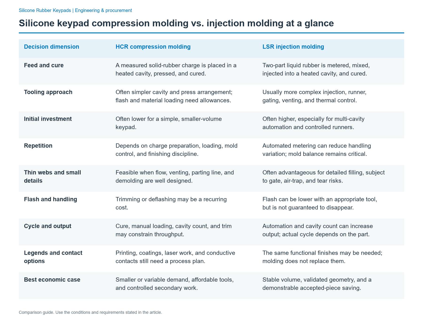
Silicone keypad compression molding vs. injection molding at a glance
The comparison below is between HCR compression molding and LSR liquid injection molding (LIM), two common keypad production routes. It is not a claim that every solid silicone must be compression molded or that all injection molding uses LSR. Solid silicone can also be injection molded. For an OEM keypad quote, name both the compound and the process so the comparison stays meaningful.
| Decision dimension | HCR compression molding | LSR injection molding |
|---|---|---|
| Feed and cure | A measured solid-rubber charge is placed in a heated cavity, pressed, and cured. | Two-part liquid rubber is metered, mixed, injected into a heated cavity, and cured. |
| Tooling approach | Often simpler cavity and press arrangement; flash and material loading need allowances. | Usually more complex injection, runner, gating, venting, and thermal control. |
| Initial investment | Often lower for a simple, smaller-volume keypad. | Often higher, especially for multi-cavity automation and controlled runners. |
| Repetition | Depends on charge preparation, loading, mold control, and finishing discipline. | Automated metering can reduce handling variation; mold balance remains critical. |
| Thin webs and small details | Feasible when flow, venting, parting line, and demolding are well designed. | Often advantageous for detailed filling, subject to gate, air-trap, and tear risks. |
| Flash and handling | Trimming or deflashing may be a recurring cost. | Flash can be lower with an appropriate tool, but is not guaranteed to disappear. |
| Cycle and output | Cure, manual loading, cavity count, and trim may constrain throughput. | Automation and cavity count can increase output; actual cycle depends on the part. |
| Legends and contact options | Printing, coatings, laser work, and conductive contacts still need a process plan. | The same functional finishes may be needed; molding does not replace them. |
| Best economic case | Smaller or variable demand, affordable tools, and controlled secondary work. | Stable volume, validated geometry, and a demonstrable accepted-piece saving. |
A premium-looking surface is not proof of either process. For both routes, the finished keypad must match the released drawing, the PCB and housing, and the same inspection conditions.
How the two processes change the manufacturing flow
Compression molding normally starts with a selected HCR compound and cure system. The operator or feeding system prepares a measured charge, positions it in an open heated mold, closes the press, and holds the required temperature and pressure while the rubber cures. The mold is opened, the keymat removed, and the parting line and any flash inspected. The process may then include deflashing, a grade-specific post-cure, cleaning, contact-related steps, graphics, protective coating, and final inspection. More cavities increase theoretical output only if filling and downstream operations keep pace.
LSR injection molding starts with two metered components, mixed in the specified ratio with compatible pigment if required. A controlled injection system feeds a hot mold through designed gates or runners. After cure, the keypad is demolded, potentially with automated handling. Gate marks, fill balance, trapped air, parting-line flash, and demolding stress still require attention. The same specification may call for surface graphics, laser processing, contact integration, cleaning, post-curing, or testing after molding.
Cure chemistry affects finishing independently of the machine. HCR is available with peroxide or platinum-addition cure systems; typical LSR is a two-part platinum-addition system. Peroxide-derived byproducts can make post-curing important. Addition cure does not make every keypad automatically post-cure-free: the material grade, cleanliness, odor or volatile limits, and application requirements determine the actual recipe. Request the compound and process records behind each proposal.
Compare tooling and geometry on the same drawing
The strongest comparison begins with the keypad cross-section and assembly stack, not a catalog tolerance number. A web that must flex repeatedly, a tall isolated key, or a narrow shutoff near a legend can fail in either tool if the design is unsuitable.
Webs, keycaps, and draft. Identify the thinnest web, its angle, thickness transitions, corner radii, and the intended bending direction. Compression tools need a sound material-distribution and venting strategy; LSR tools need balanced flow and reliable evacuation of air. On either route, excessively thin material can tear at demolding or fatigue in service. Specify the required peak force, force drop, return force, and travel rather than assuming a hardness alone sets tactile feel.
Parting lines and cosmetic faces. Mark allowed flash zones, gate or witness locations, and no-flash surfaces on the drawing. A compression tool may need additional trimming access. A well-designed LSR tool can reduce trimming, but mismatched tool faces, excessive pressure, damaged seals, or worn vents can still produce flash. Examine real pilot parts, not a general claim of “flash-free” molding.
Critical dimensions. Call out contact-center position to PCB datums, web thickness, overall key height, enclosure fit, and any sealing flange. Use the same conditioned sample age, measurement fixture, temperature, and cavity sampling for both trials. Polymer shrinkage, cure, post-cure, pigment, part geometry, and demolding can affect dimensions; a blanket precision number does not qualify an assembled key.
Tool output. Compare actual cavity count, cycle time in seconds per shot, accepted pieces per shot, available machine hours per year, and changeover losses. A small keymat may allow more cavities than a large panel. If the pad needs several graphics colors or finishing passes, the fastest molding cell may not be the fastest complete production line.
Key feel, PCB contacts, and finishes stay in the specification
Both molding routes must deliver a functioning switch interface. For a conductive-contact design, locate the contact relative to the PCB pad and support structure. Define the contact system explicitly: molded-in carbon pill, printed conductive contact, conductive silicone contact, or nonconductive actuator operating a separate switch. These are design alternatives, not an ordered quality ranking. Each needs compatible molding and verification steps; do not assume the same tooling or resistance test applies to all four.
Key feel should be compared as measured force-displacement curves: peak actuation force, force at electrical closure, bottom-out travel, return force, hysteresis, and adjacent-key interaction. A useful premium qualification objective for a frequently used industrial key is 1,000,000 full actuations per selected key, tested at the specified travel, mounting condition, PCB, actuation rate, and operating environment. This is a proposed project design target—not a guaranteed rating of either process. Define pass/fail limits for force shift, missed closure, tearing, and legend wear before testing.
Backlighting also creates work beyond molding. Light-transmitting compounds, opaque masking, printed legends, and laser-removed coatings must be matched to the actual LED location and enclosure light barriers. Include dark-room inspection for leakage, font legibility, color consistency, and abrasion after use. Extra print colors, protective coatings, or an epoxy top increase finishing, setup, inspection, and reject costs regardless of the molding route.
A keypad that meets a loose-part dimensional check can still fail when its housing compresses the perimeter, the PCB bends, or its key cap rubs the bezel. Always test the installed assembly, with the intended contact finish, support, torque, and cleaning exposure. Sealing performance is a housing-and-keypad-system result; it cannot be inferred from choosing LSR or compression molding.
Where HCR compression molding wins—and where it does not
Choose compression for a defined low-investment path when the shape can be filled and released reliably, cosmetic flash limits are practical, the product may undergo drawing revisions, and demand does not repay a more elaborate injection tool. The route is also useful when a selected HCR grade or curing system is central to the requirement. Operators can often accommodate limited model variation without building an automated feeding and runner system for every variant.
Its limits are economic and operational, not proof of inherently inferior quality. Preparing charges, loading cavities, trimming flash, handling parts, and scheduling post-cure can consume labor or add variation. A large keypad may fit relatively few cavities. A quote showing only press-cycle cost hides those losses. Demand a yield-inclusive cost for packed, accepted parts and monitor the shift-to-shift spread of force and critical dimensions.
Compression is a poor starting point when pilot builds repeatedly show incomplete filling at a delicate web, unmanageable flash at a visible edge, or insufficient line capacity after realistic secondary processing. The remedy may be a redesigned compression tool, a different keypad geometry, or another process—not automatically an LSR replacement.
Where LSR injection molding wins—and where it does not
Choose LSR injection for controlled scale when stable geometry and demand support the extra tooling investment, the part benefits from metered feeding or multi-cavity automation, and the complete production process can preserve that repeatability through inspection and finishing. Low manual handling may help control cleanliness and labor. Gate and runner design can reduce material waste, and planned inserts or overmolded features may make an injection-based architecture attractive.
The disadvantages deserve equal weight. Injection tooling, mixing and metering equipment, temperature management, gate control, vents, automation fixtures, and process qualification can increase fixed cost and development work. Thin walls may fill readily yet tear on release; trapped air, cure inhibition, weld features, gate marks, and multi-cavity imbalance can still spoil a keypad. A high-output molding machine does not lower the cost of laser marking or multi-pass printing by itself.
LSR is a weak economic choice when volume is uncertain, key artwork and geometry change frequently, or the molding-cell saving is smaller than tooling amortization and requalification. It is also unsuitable as quoted if the proposed LSR grade or manufacturing plan cannot satisfy the contact, surface, or environmental requirements. Compare qualified samples before treating “injection” as a performance specification.
Keypad process selection matrix
Use the following matrix with the same part geometry, finished-part acceptance criteria, and annual demand forecast. A preference is a starting trial route, not permission to skip qualification.
| Your project input | Start with compression when… | Start with LSR injection when… | Hold the choice when… |
|---|---|---|---|
| Forecast and revisions | Demand is variable; several drawing changes are likely. | Demand and design are stable across multiple years. | No approved forecast or revision-control plan exists. |
| Investment | Simpler tool cost determines feasibility. | Larger tool cost can be recovered from accepted-piece savings. | Quotes exclude tooling ownership, repairs, or qualification. |
| Web and detail | Pilot fill, release, and force curves meet the drawing. | Metered filling or intricate cavity control offers demonstrable improvement. | Either trial tears webs or misses a critical dimension. |
| Contact to PCB | A proven contact placement and assembly process is available. | Insert/placement and cavity control are validated on the intended circuit. | PCB pad, support, contact type, or rest gap is undefined. |
| Graphics and light | Trimming and manual work do not damage visible surfaces. | Automation reduces handling without harming masking and legends. | Both quotations omit printing, laser, coatings, or rejection. |
| Capacity | Cavities and finishing stations meet peak weekly demand. | An automated cell meets demand with verified uptime and yield. | Shot rate is quoted without finishing or good-part yield. |
| Qualification | Installed-assembly reliability passes on compression samples. | Installed-assembly reliability passes on injection samples. | No common force, contact, wear, or environmental test exists. |
When neither route passes, do not buy tooling on the strength of projected unit cost. Rework web geometry, parting-line location, contact stack, tooling access, or finishing architecture and rerun the comparison. A different HCR transfer or injection route may be worth feasibility discussion, but it requires its own quote and testing rather than being silently treated as equivalent to LSR.
When does annual volume justify switching keypad processes?
There is no universal annual-volume threshold. The crossing point depends on differential tooling and qualification expense, complete accepted-unit cost, volume over the commercial life, changes in artwork or geometry, and the cost of capacity or field failure. Use total accepted keypads over the program, not the most optimistic peak year.
For a practical planning benchmark, compare 100,000 accepted keypads/year over three years, then stress-test the same design at 20,000, 50,000, and 250,000 accepted keypads/year. Those are modeling scenarios, not standard market order tiers or minimum order quantities. The economic model is:
Three-year cost = tooling and launch qualification (USD) + accepted keypads over three years (pieces) × fully processed cost (USD/accepted keypad).
Break-even lifetime pieces = [LSR fixed cost − compression fixed cost] ÷ [compression accepted-piece cost − LSR accepted-piece cost], provided the denominator is positive. Include material, molding, operator labor, flash removal, post-cure, graphics, coating, inspection, scrap, packaging, and reasonable rework in each piece cost. Treat freight, duties, inventory, and financing consistently if they differ.
Illustrative three-year business case (not supplier pricing)
Assume both routes already pass the same design and test limits. HCR compression has $18,000 tooling + $4,000 launch qualification = $22,000 fixed, and $1.20 per accepted keypad. LSR injection has $65,000 tooling + $10,000 launch qualification = $75,000 fixed, and $0.76 per accepted keypad. The fixed-cost premium is $53,000; the unit saving is $0.44. The implied crossover is 120,455 accepted keypads over the program, about 40,152 per year over three equal years. A forecast near that value deserves a sensitivity review, not an automatic process change.
| Accepted keypads/year | Three-year units | Compression total (USD) | LSR total (USD) | Lower modeled total |
|---|---|---|---|---|
| 20,000 | 60,000 | $94,000 | $120,600 | Compression by $26,600 |
| 50,000 | 150,000 | $202,000 | $189,000 | LSR by $13,000 |
| 100,000 | 300,000 | $382,000 | $303,000 | LSR by $79,000 |
| 250,000 | 750,000 | $922,000 | $645,000 | LSR by $277,000 |
At the 100,000/year planning reference, the illustrative LSR saving is $79,000 over three years before any unmodeled program risks. This is a calculation from stated assumptions, not a quotation, predicted JASPER price, or proof that LSR can mold every drawing.
A break-even result is sensitive to the difference in accepted-piece prices. Keeping the illustrative $53,000 fixed-cost premium unchanged gives:
| LSR saving per accepted keypad | Crossover over entire program | Approximate three-year annual equivalent |
|---|---|---|
| $0.25 | 212,000 pieces | 70,667 pieces/year |
| $0.44 | 120,455 pieces | 40,152 pieces/year |
| $0.60 | 88,334 pieces | 29,445 pieces/year |
If the injection route has no positive accepted-piece saving, the simple cost model has no positive-volume break-even. If contact placement, tool rework, color-change waste, an extra coating station, or additional testing changes the cost difference, recalculate it. Also compare the capacity needed during seasonal peaks: an inexpensive route that cannot ship required good parts on time is not truly less costly.
Qualify both routes before production release
A production decision should pass three distinct gates rather than rely on a glossy molded sample.
Gate 1 — design and quotation parity. Freeze the same revision of the 2D/3D keypad drawing, key count, dimensions, web sections, artwork, compound requirements, carbon-pill or switch interface, and housing/PCB stack for both suppliers or processes. Record cavity count, tooling responsibilities, change charges, color and legend setup, projected volumes, and the fully finished cost definition. Flag any proposed design deviations.
Gate 2 — tool and pilot evidence. Sample each cavity and record critical dimensions, visual flash, fill defects, force-travel traces, key return, electrical closure, and printing adhesion. Test the specified PCB under actual mounting support and enclosure compression. Run wear, cleaning, thermal and humidity exposures appropriate to the product; for the premium objective above, cycle selected keys to 1,000,000 actuations with declared speed, travel, environment, and failure limits. The process that reaches a target first is not automatically accepted without the rest of the matrix.
Gate 3 — production economics and control. At planned lot sizes, time loading or metering, mold cure, demold, trimming, post-cure, printing, coating, inspection, and packing. Count accepted pieces rather than theoretical shots, and check cavity-to-cavity and lot-to-lot stability. Put traceability, revalidation triggers, maintenance, wear limits, and change approval into the release package. Use a controlled sample from the production-intent process as the comparison reference.
RFQ handoff: the minimum common record
An actionable keypad process quote specifies the entire input set, not just a CAD file. The following example structure can be copied into an engineering request; illustrative entries must be replaced with the actual project values.
| Record field | What to provide or define |
|---|---|
| Keypad geometry | Released drawing revision, overall envelope, key and web sections, sealing surfaces, allowable flash and gate areas. |
| PCB and enclosure | PCB contact artwork, pad finish, board support, stack-up tolerances, enclosure drawings, fastening and compression conditions. |
| Tactile response | Force-displacement target curves, measured stroke, electrical closure point, return-force and failure limits. |
| Contact architecture | Carbon pill, conductive print, conductive silicone, or separate-switch actuator; required electrical verification. |
| Graphics and lighting | Character art, colors, masking, coating, laser-marking areas, LED arrangement, illumination acceptance. |
| Service conditions | Cleaning agents, temperature and humidity exposures, expected use profile, wear and life-test plan. |
| Demand and versions | Annual forecasts and peaks, product life, variants, revision cadence, order lot sizes. |
| Commercial comparison | Tool/fixture ownership, qualification cost, accepted-piece quote, cavity count, cycle, yield, secondary operations, repair and revalidation. |
| Approval evidence | Dimensional reports, cavity records, installed-force traces, contact tests, visual/legend inspection, functional cycling and controlled drawing revision. |
For a starting economic sensitivity study, the example 100,000 accepted keypads/year for three years is a useful high-volume planning reference. It is not a reason to delete the lower and higher forecasts or to skip the user's actual duty-cycle target.
Frequently asked questions
Is compression molding or LSR injection molding better for high-volume keypads?
LSR injection is often the first process to investigate for stable high-volume programs because controlled metering and automated demolding may lower accepted-piece costs. Compression can still win with a proven multi-cavity tool, low downstream labor, or higher injection-tool qualification costs. Compare both at the same forecast, geometry, complete finishing scope, and good-part yield before choosing.
Are HCR and LSR the same distinction as compression and injection molding?
No. HCR and LSR describe material formats, whereas compression and injection describe manufacturing processes. HCR is commonly compression molded but can also be transfer or injection molded. LSR is commonly processed by liquid injection molding. A meaningful keypad RFQ specifies the material grade, cure chemistry, process, tooling design, and finished-product tests instead of treating the pairs as interchangeable labels.
At what annual volume should we switch from compression to injection?
There is no universal switch volume. In the illustrative three-year model here, a $53,000 injection fixed-cost premium and $0.44 accepted-keypad saving cross near 120,455 lifetime keypads, or roughly 40,152 per year. These are modeled inputs, not industry thresholds. Replace the costs and lifetime forecast with qualified quotations and include setup, reject rates, finishing, and revalidation.
Which molding route produces more consistent key travel and thin webs?
LSR injection can offer an advantage where precise dosing, balanced cavities, and controlled flow are important, but process selection alone does not guarantee consistent key travel. Web geometry, shrinkage, venting, cure, and demolding all matter. Check both routes against the same web drawing and sampled force-displacement curves, with the intended PCB support and bezel installed.
Can compression-molded and injection-molded keypads both use carbon contacts and backlit legends?
Yes, both routes can be engineered around conductive contacts and illuminated legends, provided the contact-placement and graphic processes are compatible with the chosen tool and compound. Specify pill or contact type, pad alignment, rest gap, legend construction, masking, and LED geometry. Printing, laser marking, coating, and contact testing may remain separate operations whichever molding route is used.
Does LSR eliminate flash removal, post-curing, and all other finishing?
No. A well-designed LSR injection tool can reduce flash and manual handling, but gate marks, molding defects, and cosmetic requirements still need inspection. Post-cure depends on the grade, cure chemistry, and end-use requirements. Printing, abrasion-resistant coating, laser legends, cleaning, electrical checks, and packaging may still be required for the complete keypad.
Can we keep an HCR compression tool if we change to LSR injection?
Do not assume so. The injection route needs its own feed, gating, venting, sealing, and thermal strategy, often requiring a new tool rather than a direct retrofit. Some geometry or downstream fixtures may be reusable, but contact fit, shrinkage, force curves, surface finishing, and assembly behavior should be requalified as part of a controlled engineering change.
Make the choice from the installed keypad and total program cost
Start with the route that meets the geometry, contact, finish, and lifecycle gates with the least commercial risk. Then compare fully processed accepted keypads, not raw molded shots. If the forecast is low or volatile and post-processing is manageable, compression is a sound candidate. If validated LSR automation saves enough across a stable program, injection earns its extra tool investment.
For component options and the engineering scope of a custom keypad, see JASPER's silicone rubber keypad product page. To request a route comparison for your own part, send your drawing together with keypad geometry, character artwork, PCB contacts and support, force/travel targets, cleaning environment, drawing revision, and quantity forecast.
Bring the drawing, stack and operating conditions
JASPER engineering will review the interfaces, open risks and evidence required for a production quote.