
Electrosurgical grounding pad design guide covering 10 boundaries for conductors, hydrogel, CQM interfaces, packaging, and validation ownership.
JASPER certifications: ISO 9001, ISO 13485, IATF 16949, and ISO 14001.
1. What a Patient Return Electrode Does—and What “Grounding Pad” Hides
A patient return electrode completes the intended high-frequency current path during monopolar electrosurgery. The active electrode concentrates current at the surgical site. The return electrode spreads returning current over a much larger effective contact area. NICE explains the central hazard mechanism: if effective contact area falls, current can concentrate in the remaining area, increasing local current density and temperature (NICE HealthTech Guidance 290).
“Grounding pad” is familiar search language, but it can mislead. Modern systems are not defined simply by connection to earth ground. Patient return electrode and return electrode describe the circuit role; dispersive electrode describes current spreading; IEC 60601-2-2 uses the term neutral electrode. Engineering decisions should use the term that matches the circuit role.
In the United States, FDA classifies an electrosurgical patient return electrode under product code ODR, Class II, associated with 21 CFR 878.4400 and the 510(k) pathway (FDA ODR classification record). That classification belongs to the finished device. A printed conductor, converted laminate, lead attachment, or die-cut layer does not inherit clearance from a customer, predicate, material supplier, or generator.
2. Patient Return Electrode Construction Is a System, Not a Layer List
A common disposable patient return electrode is a laminated system. FDA's ODR record describes a representative five-layer construction with a removable Mylar cover, conductive gel, dual aluminum electrode, acrylic adhesive, and polyethylene foam backing. FDA 510(k) K023812 documents a different named example using a siliconized PET release liner, acrylic-coated carrier, aluminum conductors, hydrogel, and protective packaging (FDA ODR record; FDA K023812). Neither record is a universal recipe.
Functional stack diagram
PATIENT / SKIN SIDE
removable release liner
removed before use
conductive hydrogel or other specified patient-contact interface
nonconductive border adhesive / fluid-control geometry where designed
transfers RF current and maintains the intended contact footprint
conductive region A isolation gap conductive region B
solid, split/dual, or another defined architecture
carrier / dielectric / backing laminate
provides handling, conformability, edge control, and load transfer
terminal tabs, clamp zone, cable attachment, or printed tail
connects to the named generator/accessory interface
primary package and labeling system
preserves the released configuration through transport and claimed life
GENERATOR / SYSTEM SIDE
Every line in the stack changes another line. Hydrogel footprint changes effective electrical contact. Border adhesive and fluid-control geometry affect lift and ingress paths. Conductor edges influence current distribution. Backing stiffness affects conformability and crease behavior. A cable joint shifts mechanical load into the laminate. Packaging can compress, fold, contaminate, or dry the interface before the device reaches use.
Construction decision table
| Architecture | Monitoring relationship | Public precedent | Main design burden | Not the best choice when |
|---|---|---|---|---|
| Solid conductive disposable pad | May support continuity-only behavior in a defined system | FDA K251235 distinguishes solid and split configurations | Conductor/contact area, thermal performance, attachment, labeling, generator compatibility | The intended generator requires split-electrode contact-quality monitoring |
| Split or dual-foil conductive pad | Two isolated conductor regions can support a compatible CQM system | FDA K023812, K060255, K100047, K251235; 3M 8180F/1182 | Split geometry, isolation, monitoring range, connector mapping, partial-lift response | Generator and electrode were not validated as a compatible pair |
| Conventional aluminum-foil laminate | Directly represented in multiple FDA records | FDA ODR description, K023812, K203293 | Foil conversion, edge geometry, laminate integrity, hydrogel, termination | Required geometry/process cannot be controlled, or the complete construction fails system validation |
| Grounding pad printed circuit candidate | Patent and biomedical-electrode precedent exists for printed conductors on polymer films; direct public return-pad evidence is sparse | US7904180B2; WO2007019115A1 | RF impedance, current distribution, thermal mapping, flex/crease, cure, aging, interface and termination validation | The project expects low-voltage continuity to prove RF/thermal equivalence to foil |
| Large-area capacitive or reusable return system | Uses a different coupling and monitoring architecture | NICE review of Mega Soft; FDA-cleared examples exist under other records | Equipment integration, dielectric/capacitive performance, cleaning/reuse, system controls | A thin disposable skin-adhesive pad is the fixed product architecture |
The architecture decision comes before artwork. A split conductor is not automatically “safer,” and a solid conductor is not automatically obsolete. The legal manufacturer must match the electrode architecture to the named generator, intended patient population, mode of use, protective monitoring, risk controls, and currently applicable standards.
Failure chain to review before artwork release
| Initiating condition | Local construction effect | Potential system consequence | Evidence owner |
|---|---|---|---|
| Partial lift or fluid reaches the contact boundary | Effective contact changes or becomes uneven | Local current concentration and temperature rise | Legal manufacturer, with supplier material/process evidence |
| Split gap or terminal mapping is wrong | Monitoring channels no longer represent the released geometry | CQM response may not match the intended fault condition | Legal manufacturer and compatible-system test owner |
| Printed conductor creases or cures outside its window | Electrical behavior changes at the bend, edge, or overlap | Unstable RF path or local heating may develop | Component supplier for process controls; legal manufacturer for system effect |
| Cable load peels the terminal transition | Conductor/contact path becomes intermittent or narrowed | Fault, monitoring response, or current distribution can change | Joint owner plus finished-system validation owner |
| Package or aging changes hydrogel and liner condition | Contact, release, adhesion, or geometry shifts before use | Released device may no longer match validated performance | Legal manufacturer, package owner, and contracted suppliers |
3. The Ten Electrosurgical Grounding Pad Design Boundaries
An electrosurgical grounding pad design is ready for supplier review only when ten boundaries share one revision chain: intended use, generator, conductor geometry, printed-conductor evidence, mechanical stack, skin interface, connection, package, validation ownership, and change control.
3.1 Intended use, patient population, and regulatory role
Start with what the finished device is meant to do. The input set should name monopolar use, procedure or system context, patient population, single-use or reuse model, sterile or nonsterile state, expected users and environment, target markets, and the legal manufacturer. Patient weight may be one labeled selection factor in a named product, but it is not the entire design basis.
The 3M 8180F is one useful illustration, not a template: its IFU identifies 129 cm² for a manufacturer-labeled configuration for patients over 15 kg, while the 1182 is 65 cm² for patients at or below 15 kg (3M IFU). Those values belong to those products, materials, labels, and compatible systems.
a signed design input identifies intended use, users, environment, patient population, regulatory markets, device owner, and supplied component boundary.
“adult electrosurgical grounding pad” is the complete intended-use statement.
3.2 Generator and contact-quality monitoring are controlled interfaces
A return electrode and an electrosurgical generator form one safety-relevant interface. The specification should name the generator family, connector or clamp, solid/split/capacitive architecture, continuity or contact-quality monitoring behavior, alarm response, and compatibility evidence expected before release.
FDA K251235 identifies its split pads as intended for generators with contact-quality monitoring systems such as REM, ARM, and NESSY, while solid versions are intended for generators without CQMS (FDA K251235). That statement does not make every split electrode interchangeable. Medtronic's REM and ERBE's NESSY are named system implementations. ERBE's published 20–120 Ω activation range is a product/system example, not an industry-wide design target (ERBE VIO NESSY brochure).
the interface-control document names generator, cable/clamp, electrode type, monitoring behavior, fault states, and test configuration.
the drawing says “universal REM pad” without a compatible-system list or system-level evidence.
3.3 Conductive geometry is not the external patch outline
The design file must separate at least five geometries: external converted outline, conductor region or regions, hydrogel/contact footprint, nonconductive adhesive border, and dielectric/keep-out areas. A split design also needs the isolation gap, segment identity, connector mapping, orientation rules, and any perimeter or equipotential feature under configuration control.
Current distribution does not follow a marketing silhouette. Conductor edges, corners, partial contact, hydrogel boundaries, lift direction, anatomy, and cable orientation can shift the effective path. FDA K023812 documents an omega-shaped equipotential concept in a named product, while patent literature describes other edge-management approaches. Those examples demonstrate that geometry matters; they do not authorize copying proprietary shapes or claiming freedom to operate.
native vector artwork uses datums and separate layers for conductor, gap, gel, adhesive, dielectric, cut, and terminal features.
one PDF outline is scaled until it fits a package, with no electrical coordinate system.
3.4 A grounding pad printed circuit requires RF and thermal evidence
A grounding pad printed circuit may offer patterned geometry and integration advantages, but printability is not the release criterion. Printed silver, carbon, or hybrid conductors have material-specific sheet behavior, thickness variation, cure response, edge definition, flex sensitivity, interface chemistry, and aging mechanisms. The complete return path also includes overlaps, terminals, cable joints, hydrogel, and skin contact.
Patent records such as US7904180B2 and WO2007019115A1 describe conductive ink on dielectric or polymer substrates in biomedical-electrode concepts (US7904180B2; WO2007019115A1). By contrast, the FDA examples reviewed for conventional disposable return electrodes most often identify aluminum foil. That evidence gap should change the development plan: printed construction starts as a feasibility candidate, not an assumed equivalent.
the program links ink grade, print thickness, cure window, geometry, RF method, thermal mapping, flex/crease, aging, terminal, and finished-system tests.
a room-temperature multimeter continuity check is the sole electrical acceptance test.
3.5 Substrate, dielectric, and backing control conformability and load
“Flexible PET” is not a material specification. The bill of materials should name exact substrate, carrier, dielectric, foam/backing, and reinforcement grades with thicknesses and approved suppliers. Drawings should define folds, creases, free-flex zones, cut edges, laminate overlaps, fluid pathways, and areas that must remain flat.
A stiff carrier may simplify printing and converting but resist body contours. A compliant backing may conform well but complicate registration, cable load transfer, and pack handling. A dielectric protects noncontact regions, yet its edge and overlap can create a stiffness or fluid boundary. The chosen stack must survive production, packaging, application, generator activation, removal, and claimed storage—not just flat-bench inspection.
mechanical samples use production materials and packed conditioning before flex, application, and electrical checks.
the team selects backing softness by hand feel, then freezes conductor artwork before crease and load testing.
3.6 Hydrogel, adhesive, and skin interface remain finished-device concerns
Conductive hydrogel transfers current between the patient's skin and conductor. A separate nonconductive border adhesive may support retention and help control fluid ingress. FDA K060255 and K100047 describe this functional separation in named products, and Medtronic distinguishes the PolyHesive conductive hydrogel from an acrylic adhesive/fluid barrier (FDA K060255; FDA K100047; Medtronic product documentation).
Material names do not prove biological safety or use performance. FDA's 2023 ISO 10993-1 guidance uses a risk-based evaluation that considers the final finished device, materials, manufacturing, contact nature, and contact duration (FDA ISO 10993-1 guidance). Peel data from ASTM D3330/D3330M-04(2025) can support a defined tape or laminate method; it cannot establish skin retention, painless removal, irritation response, fluid resistance, or surgical-use suitability (ASTM D3330).
exact hydrogel, border adhesive, liner, footprint, thickness, application/removal sequence, conditioning, aging, and biological-evaluation owner are named.
“medical-grade adhesive” is accepted as the patient-interface specification.
3.7 Lead, clamp, cable, and printed tail define two load paths
The electrical path and mechanical path should be drawn separately. A split electrode may need isolated conductor paths through the terminal and cable. A cordless pad may use a defined clamp accessory. A corded pad adds attachment workmanship, conductor isolation, wire routing, strain relief, package volume, and external connector compatibility.
Map the electrical route from each conductor region to the named generator input. Then map cable pull, torsion, snag, bending, and package compression into the carrier and adhesive. A joint can remain continuous while beginning to peel; a mechanically intact cable can still have unstable impedance under motion. Production inspection should therefore include defined electrical nodes and a mechanically representative fixture.
conductor map, cable/clamp drawing, pinout, attachment cross-section, strain boundary, pull axes, and packed orientation share one controlled revision.
a lead is added after the laminate passes bench electrical tests.
3.8 Packaging, storage, and shelf life are part of the electrical design
Packaging can change hydrogel moisture, liner release, adhesive behavior, conductor flatness, cable loading, and terminal cleanliness. The input set should identify sterile or nonsterile state, primary package, barrier requirement, seal zone, label/UDI inputs if applicable, cable orientation, transport distribution, storage range, aging plan, and post-aging test matrix.
ISO 11607-1:2019 applies to packaging systems intended to maintain sterility for terminally sterilized medical devices; it is relevant only if that is the finished-device claim (ISO 11607-1). FDA recognizes ASTM F1980-21 for accelerated aging of sterile barrier systems ; real-time studies remain necessary to confirm accelerated-aging results (FDA ASTM F1980 recognition). A nonsterile product still needs its own package and shelf-life evidence.
aged, distributed, and production-packed devices repeat critical electrical, adhesive, package, and functional evaluations.
shelf life is copied from a hydrogel datasheet before the final laminate and pouch exist.
3.9 Component verification and finished-system validation are separate gates
FDA's March 2020 electrosurgery guidance identifies neutral-electrode thermal performance, contact impedance, and adhesion as key evaluation categories under the currently recognized IEC 60601-2-2 edition (FDA electrosurgery guidance). FDA's standards database currently lists IEC 60601-2-2 Edition 6.1 for high-frequency surgical equipment and accessories (FDA recognition record).
A component supplier may inspect dimensions, registration, conductor continuity or another agreed electrical property, dielectric coverage, terminal workmanship, laminate features, and package attributes. That work can feed the device file. It cannot replace generator compatibility, thermal performance in the applicable configuration, CQM fault response, biological evaluation, usability, labeling, shelf life, or the legal manufacturer's risk acceptance.
every verification row names a method, fixture, sample state, acceptance criterion, owner, record, and revalidation trigger.
the supplier's certificate of conformance is treated as proof that the return electrode is safe with a named ESU.
3.10 Transfer and change control preserve the validated configuration
A released patient return electrode is a configuration, not a part number alone. Material supplier, ink or foil grade, hydrogel, adhesive, backing, liner, print/cure process, conductor artwork, terminal, cable, package, sterilization if any, inspection method, and labeling may all affect evidence.
ISO 14971:2019 frames risk management across the device lifecycle, including control implementation and monitoring of control effectiveness (FDA recognition 5-125). Change review should therefore ask whether a proposed substitution can alter RF current distribution, heat, adhesion, biological response, monitoring behavior, packaging life, or user interaction. “Form, fit, and function” is not enough when the evidence depends on a material or process detail.
the quality agreement defines notification thresholds, evidence package, approval authority, traceability, and revalidation logic.
procurement can substitute ink, gel, adhesive, backing, or cable after matching only a family description.
4. When a Printed Construction Is—and Is Not—the Best Choice
A printed conductor may be worth investigating when the electrode requires patterned isolation, integrated routing, repeatable multi-region geometry, a thin tail, or alignment with other printed layers. Those advantages concern manufacturing architecture. They do not settle safety or regulatory questions.
A conventional aluminum-foil laminate has a stronger public evidence trail for disposable patient return electrodes. FDA's ODR description and 510(k)s K023812, K203293, K060255, and K100047 all document foil-based or conventional conductive constructions. A design team proposing printed ink should expect an evidence bridge that addresses the complete RF path rather than claiming material equivalence.
Printed construction is not the best choice when:
- the business case depends on substituting ink without RF and thermal feasibility work;
- production cannot control print thickness, cure, conductor edges, isolation gaps, or lot-to-lot electrical behavior;
- expected bending, creasing, or cable load exceeds the demonstrated capability of the printed/dielectric stack;
- hydrogel or adhesive chemistry is incompatible with the conductor or dielectric system;
- the conductor-to-terminal transition creates a narrow or unstable current path;
- a named generator requires a validated electrode architecture that the printed design has not demonstrated;
- the program lacks time, samples, fixtures, or ownership for integrated IEC/FDA-aligned testing;
- freedom-to-operate review has not covered relevant electrode geometry and monitoring patents.
A printed design can still succeed. The correct starting statement is “candidate architecture requiring system evidence,” not “equivalent replacement for foil.”
5. Run the Project From System Definition to Controlled Transfer
The buyer process below keeps sourcing activity behind the safety-relevant decisions instead of asking a supplier to guess them.
Step 1 — Freeze the intended system and ownership
Identify the legal manufacturer, intended use, patient population, markets, generator families, monitoring architecture, reusable/disposable model, sterile state, users, environments, and regulatory strategy. Create a responsibility matrix before requesting prices. If any field is unknown, label it open rather than hiding the gap in a generic specification.
Step 2 — Release an interface-control package
Provide layered conductor, dielectric, gel, adhesive, cut, and terminal artwork; datums; material candidates; cable/clamp/connector drawings; package concept; and system interface. State which dimensions are critical to current distribution, monitoring, fit, fluid control, or user application. Native vector files should govern tooling; a rendered PDF should not be the only source.
Step 3 — Screen materials and process coupons
Use coupons to study print or foil consistency, dielectric coverage, lamination, gel/adhesive compatibility, terminal transitions, cure, and relevant conditioned states. Coupons answer narrow feasibility questions. They do not carry a patient-use conclusion and should not be presented as finished-electrode approval.
Step 4 — Build integrated engineering samples
Build the full released stack with production-intent materials, conductor geometry, terminal, cable or clamp, liner, and package. Include variants that expose likely failure modes: edge lift, split-gap registration, conductor crease, fluid path, cable load, and pack compression. Record all deviations rather than silently hand-building around them.
Step 5 — Execute component verification and finished-device validation
Use the JASPER quality and testing framework to define quoted component checks only after capability is confirmed. In parallel, the legal manufacturer owns or controls IEC 60601-2-2-aligned neutral-electrode work, generator/CQM behavior, biological evaluation, packaging and shelf life, risk controls, usability, labeling, and regulatory evidence.
FDA's 2016 human-factors guidance calls for intended-user/use-environment analysis, use-related risk analysis, critical-task identification, formative work, and human-factors validation (FDA human-factors guidance). For a return electrode, critical tasks may include selection, site preparation, application, connector engagement, alarm response, removal, and disposal. The exact task set belongs to the finished device and workflow.
Step 6 — Transfer one controlled configuration
Link BOM, artwork, process specification, inspection methods, fixtures, sample conditioning, package, labeling, risk controls, and change-notification terms. Define which changes require document review, partial verification, or broader revalidation. Production release is not the point when supplier and device files diverge; it is when their boundaries become traceable.
6. Return Electrode Manufacturer Inputs: Drawing and RFQ Checklist
The phrase return electrode manufacturer inputs should mean a controlled data package, not a request for a supplier to design safety-critical functions from a sketch. The broader JASPER electrode-pad product family provides context for printed and converted electrode components; the actual quotation must identify the delivered boundary.
| Input block | Minimum controlled content | Why it matters |
|---|---|---|
| Intended use and ownership | Legal manufacturer, device role, patient population, users, environment, markets, single-use/reuse, sterile state | Sets validation and regulatory context |
| Generator interface | Named generator(s), mode, CQM/continuity architecture, cable/clamp/connector, pinout, compatibility owner | Prevents unsupported “universal” claims |
| Geometry | External outline, conductor regions, split gap, gel/contact area, adhesive border, dielectric, keep-outs, datums, tolerances | Separates mechanical outline from current path |
| Materials | Exact foil or ink, substrate, dielectric, backing, hydrogel, adhesive, liner, terminal, cable, approved alternates | Connects evidence to one configuration |
| Printed circuit | Native artwork, conductor thickness target, cure, overlap, isolation, terminal transition, test points | Makes a printed candidate manufacturable and testable |
| Mechanical interface | Cable routing, strain relief, pull/torsion axes, folds, crease limits, free-flex zones, clamp engagement | Controls hidden load paths |
| Package | Pouch/tray, barrier need, seal zone, pack orientation, label inputs, storage, transport, aging plan | Preserves gel, adhesive, conductor, and terminal state |
| Acceptance | CTQs, method, fixture, frequency/current where applicable, conditioning, sample state, limits, sampling, report | Makes results reproducible |
| Responsibility | Supplier checks, legal-manufacturer tests, third-party lab work, approval authority, deviations, change notification | Prevents component inspection from being mistaken for device validation |
7. Sample Approval and Finished-Device Validation Need Different Evidence
A component can match its drawing and still fail in the finished electrosurgical system. The approval matrix should keep supplier evidence useful without letting it answer a larger question than the method supports.
| Evidence block | Component/manufacturing check where quoted | Finished-device / legal-manufacturer work | Release question |
|---|---|---|---|
| Geometry and registration | Outline, conductor regions, split gap, gel/adhesive/dielectric registration, terminal location | Current distribution, partial-contact behavior, anatomy/placement, patient variants | Is the tested geometry the released geometry? |
| Conductor | Material/lot, print or foil dimensions, continuity or defined impedance/resistance method, isolation, defects | HF performance, contact impedance, thermal performance, fault conditions | Does the component method correlate with RF system behavior? |
| CQM / continuity interface | Isolated paths, connector mapping, cable continuity, attachment workmanship | Compatible generator response, alarm/inhibition behavior, partial lift and connection faults | Was the exact generator-electrode-cable combination evaluated? |
| Hydrogel and adhesive | Grade/lot, footprint, thickness if specified, liner, laminate/process checks | Skin contact, retention, fluid exposure, removal, biological evaluation, use duration | Does the final patient-contact system match the evidence? |
| Mechanical stack | Thickness, layer registration, crease/flex or pull method where scoped | Body conformability, cable loads, placement workflow, worst-use conditioning | Does the fixture represent use and packaging? |
| Package and aging | Material identity, dimensions, seal/process checks where scoped, pack orientation | Distribution, sterile barrier if claimed, shelf life, post-aging function and labeling | Does packaging preserve every critical function through claimed life? |
| Documentation | Inspection report, material/lot traceability, deviations, revision | Risk-management file, design V&V, human factors, regulatory submission, labeling | Can the legal manufacturer reconstruct and defend the released state? |
The test plan should use the current, licensed standards and regulatory requirements for the target market. FDA's ODR page and recognized-standards database are useful starting points; they are not substitutes for applicability review. IEC 60601-1 Edition 3.2 provides general medical-electrical-equipment context, while IEC 60601-2-2 Edition 6.1 is the particular standard for HF surgical equipment and accessories (IEC 60601-1; IEC 60601-2-2).
8. Release Blockers That Should Stop Supplier Release
These failures override a polished sample or low quotation:
- No named legal manufacturer — nobody owns the finished-device risk, validation, and regulatory file.
- No named generator or monitoring architecture — “compatible with ESUs” is not an interface definition.
- Patch outline substituted for electrical geometry — conductor, gel, adhesive, and dielectric regions are not separately controlled.
- Printed ink justified by continuity alone — RF, thermal, flex, aging, and terminal behavior remain unaddressed.
- “Medical-grade” used as an acceptance criterion — exact material, process, contact, and biological-evaluation evidence are missing.
- Packaging omitted from engineering samples — gel, liner, cable, and conductor enter validation in an unrealistic state.
- Supplier inspection presented as IEC or FDA compliance — component evidence has crossed an unsupported boundary.
- Silent material substitution allowed — a validated configuration can change without risk review or revalidation.
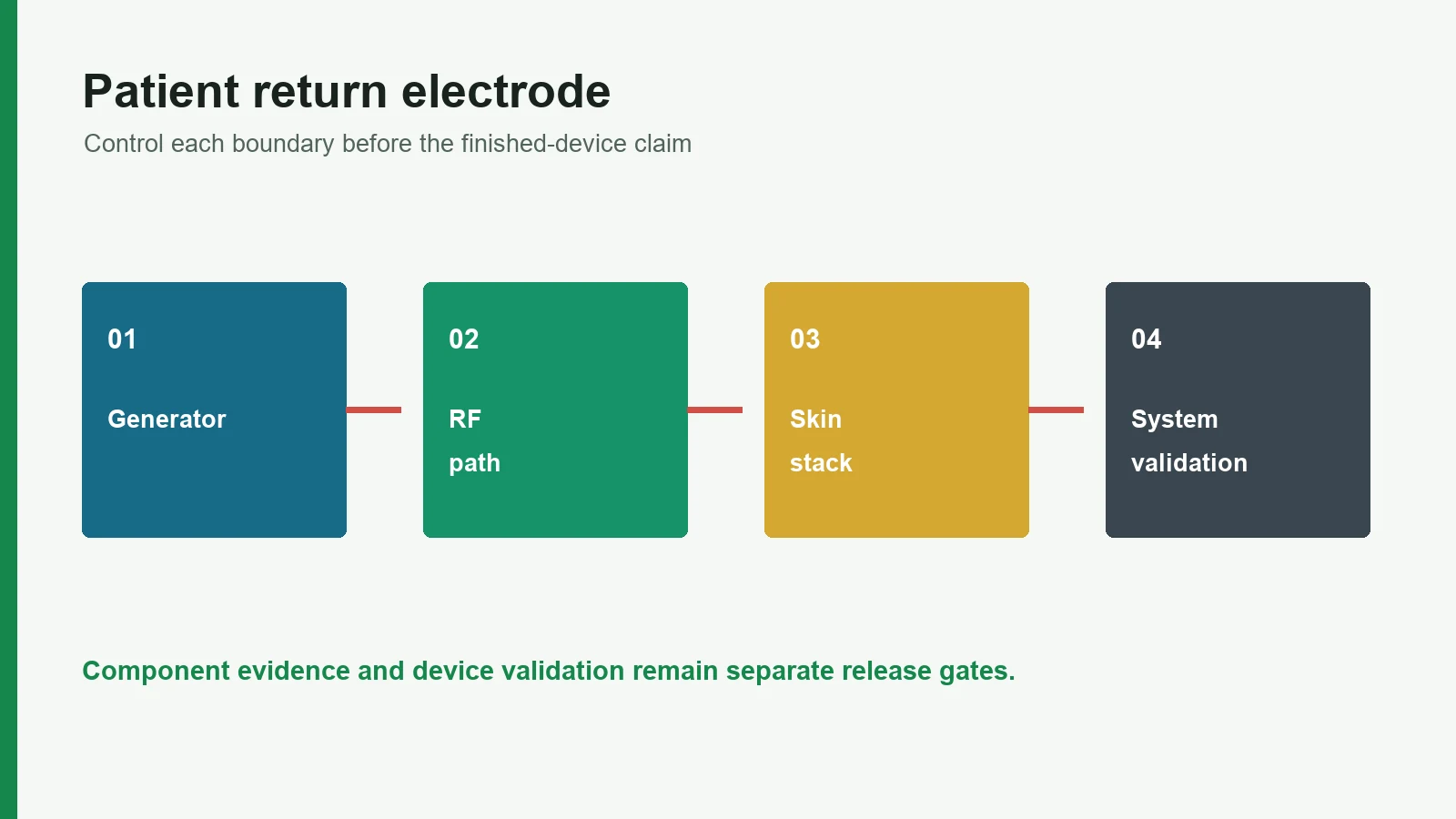
Evidence Release Matrix
| Evidence level | Controlled article | Decision |
|---|---|---|
| Material | Named grade, supplier, lot, process, and conditioning | Candidate input remains within its documented scope |
| Printed component | Released drawing, stack, geometry, connector, and inspection method | The manufactured part matches its component specification |
| Integrated assembly | Final mechanics, electronics, software, packaging, and use state | Interfaces remain functional under expected conditions |
| Finished device | Intended population, risk controls, biological and performance evidence | The legal manufacturer can release the stated claim |
9. Frequently Asked Questions
What information is required for electrosurgical grounding pad design?
The input package should define intended use, patient population, legal manufacturer, named generator and monitoring architecture, conductor and contact geometry, complete material stack, hydrogel and adhesive system, terminal/cable interface, package, acceptance methods, validation owners, and change-control rules. “Grounding pad” plus an outline is not sufficient.
Is “grounding pad” the same as “patient return electrode”?
The phrases often refer to the same accessory in ordinary use, but patient return electrode is more precise. It returns monopolar high-frequency current to the generator. “Grounding pad” can wrongly suggest that the safety function is simply an earth-ground connection.
Can a grounding pad printed circuit replace aluminum foil?
Not by assumption. Printed conductors can support patterned biomedical-electrode architectures, but public FDA examples for disposable patient return electrodes commonly identify aluminum foil. A printed replacement needs construction-specific RF, thermal, current-distribution, flex, aging, terminal, interface, and compatible-system evidence.
Does a split patient return electrode work with every CQM generator?
No. A split conductor provides two electrically isolated regions that may support contact-quality monitoring, but compatibility depends on the named electrode, cable or clamp, generator, monitoring algorithm, thresholds, labeling, and validated system behavior. REM, ARM, and NESSY names do not create universal interchangeability.
Which patient return electrode tests does FDA identify?
FDA's March 2020 electrosurgery guidance identifies neutral-electrode thermal performance, contact impedance, and adhesion as key test categories under the currently recognized IEC 60601-2-2 edition. The complete program may also need compatible-system, biological, packaging, shelf-life, usability, and other risk-based evidence.
Does “medical-grade hydrogel” prove biocompatibility?
No. A trade description does not establish biological safety. FDA's ISO 10993-1 guidance uses a risk-based evaluation of the final patient-contacting device, including materials, manufacturing, contact nature and duration, existing evidence, and any justified testing.
Who validates generator compatibility and CQM behavior?
The finished-device legal manufacturer owns the compatibility claim and risk acceptance, even when a supplier performs contracted tests. The interface plan should name the generator, electrode, cable or clamp, monitoring behavior, methods, acceptance criteria, records, and approval authority.
What should a return electrode manufacturer provide at sample approval?
The agreed package may include dimensional and registration results, material and lot traceability, conductor-path data using defined methods, isolation checks, terminal workmanship, laminate and package features, deviations, and revision records. It does not by itself prove finished-device safety, clinical suitability, shelf life, or regulatory clearance.
10. Review the Printed-Component Scope and Validation Owner
Before releasing artwork, mark each layer and test as supplier-owned component work, legal-manufacturer validation, or third-party laboratory work. Then send the named generator interface, conductor/gel/adhesive geometry, material candidates, terminal, package concept, test methods, and responsibility matrix for review.
For related stack terminology before an RFQ, see the medical electrode layer stack guide.
Technical References
- Source: FDA Use of ISO 10993-1 Biological Evaluation Guidance. Accessed 2026.
- Source: ISO 10993-1:2025 Biological Evaluation of Medical Devices. Accessed 2026.
- Source: ISO 14971:2019 Medical Device Risk Management. Accessed 2026.
- Source: FDA Design Control Guidance for Medical Device Manufacturers. Accessed 2026.
- Source: FDA ODR classification record. Accessed 2026.
- Source: FDA ODR record. Accessed 2026.
- Source: FDA K023812. Accessed 2026.
- Source: 3M IFU. Accessed 2026.
- Source: FDA K251235. Accessed 2026.
- Source: ERBE VIO NESSY brochure. Accessed 2026.
- Source: US7904180B2. Accessed 2026.
- Source: WO2007019115A1. Accessed 2026.
- Source: FDA K060255. Accessed 2026.
- Source: FDA K100047. Accessed 2026.
- Source: Medtronic product documentation. Accessed 2026.
- Source: FDA ISO 10993-1 guidance. Accessed 2026.
- Source: ASTM D3330. Accessed 2026.
- Source: ISO 11607-1. Accessed 2026.
- Source: FDA ASTM F1980 recognition. Accessed 2026.
- Source: FDA electrosurgery guidance. Accessed 2026.
- Source: FDA recognition record. Accessed 2026.
- Source: FDA recognition 5-125. Accessed 2026.
- Source: FDA human-factors guidance. Accessed 2026.
- Source: IEC 60601-2-2. Accessed 2026.
Review the printed return-electrode boundary
Send the current drawing, material stack, electrode roles, connector, use conditions, acceptance methods, program phase, and annual volume.