
An HMI for chemical processing equipment should be specified as a complete, installed hardware stack—not simply as a touchscreen with an IP label. OEM engineers should select the front surface, touch method, adhesive, gasket, bezel, circuit, connector exit and enclosure interface from the named chemicals, concentrations, temperatures, contact modes, classified-area status, gloves, washdown method, lighting and maintenance plan. The defensible recommendation is layer-specific and system-specific: verify every exposed material and joint under representative conditions. IP protection, corrosion resistance, chemical compatibility and hazardous-location approval answer different questions. PLC/SCADA programming and process-control logic are outside this hardware guide.
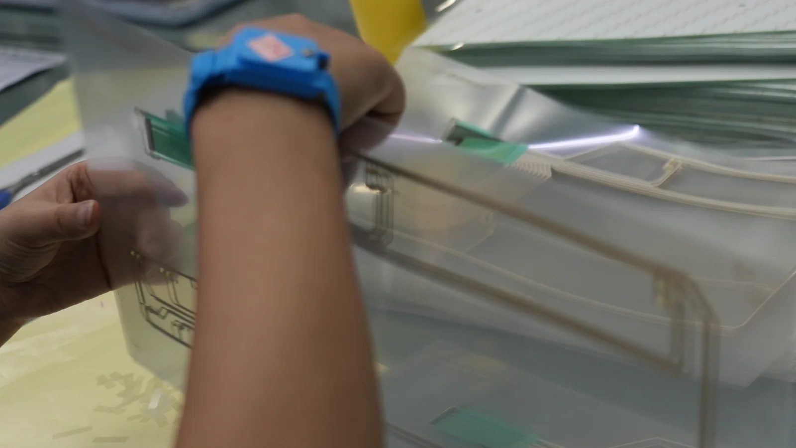
Quick decision table for chemical-processing HMI hardware
Match HMI construction to the dominant exposure, then define evidence for the installed assembly.
| Dominant condition | Construction direction to evaluate | Likely failure path | Evidence to request |
|---|---|---|---|
| Intermittent splash in a nonclassified area | Hard-coated overlay with sealed keys, or a sealed touch stack | Edge lift, ink change, gasket attack | Chemical list, coupon results, full-stack exposure report |
| Frequent washdown | Continuous front surface, controlled perimeter seal, compatible bezel and cable exits | Liquid entry at cutout, fastener or connector | IEC 60529 or NEMA/UL report for the mounted configuration plus chemistry-specific testing |
| Wet operation with chemical gloves | PCAP tuned through the final lens, or pressure-actuated resistive/membrane input | Missed touch, false touch, excess actuation force | Production-representative glove and liquid test |
| Hazardous classified location | Approved HMI, approved purged/pressurized system, or remote interface outside the classified area | Ignition-source mismatch or invalid marking | Area-classification drawing, approval certificate, marking and control drawing as applicable |
| Corrosive vapor or deposit | Chemistry-specific metal, coating, gasket and window selection | Crevice attack, coating undercut, ground-path deterioration | Materials list and exposure test with actual concentration, temperature and duration |
| Glare, condensation or outdoor viewing | Display/lens stack validated at the installed angle and ambient lighting | Washed-out alarms, reflections, obscured text | Installed-view legibility test with protective lens and expected surface condition |
A human-machine interface for chemical processing is the complete operator-facing stack
A human-machine interface for chemical processing is the physical assembly through which an operator sees equipment status and enters commands at the machine. The hardware boundary includes the viewing and input surfaces, their circuits and seals, and every interface that allows the assembly to mount, connect and bond to the host enclosure. For broader foundational terminology, see What Is an HMI Panel? Hardware and OEM Guide.
In manufacturable HMI assemblies, the relevant stack commonly includes:
- Protective face: printed hard-coated film, coated glass or another specified lens.
- Display window: clear region, optical interface, display module and backlight.
- Input layer: PCAP, resistive touch, membrane switch, discrete keys or a hybrid.
- Graphics: reverse-printed inks, legends and status windows.
- Bonding layers: pressure-sensitive or optical adhesive and spacers.
- Seal: perimeter gasket, formed seal or bonded flange.
- Circuit: flex tail or PCB, shielding and connector termination.
- Mechanical interface: bezel, fasteners, cutout, mounting land and strain relief.
- Electrical interface: bonding point, cable shield, power/data connector and chassis relationship.
The HMI is not the PLC program, SCADA database, alarm philosophy or safety-instrumented logic. Those systems may drive the display, but a front-panel manufacturer controls only the hardware layers and documented interfaces. Freeze the exposure and enclosure requirements before selecting the display.
Front-panel construction should follow the exposure and operator task
No single front-panel technology is best for every chemical process.
| Hardware variant | Strong use condition | Main tradeoff to resolve | Prototype question |
|---|---|---|---|
| Hard-coated polyester overlay with membrane keys | Compact commands, tactile landmarks and sealed graphics | Edge exposure, embossing fatigue, adhesive and ink compatibility | Is tactile feedback clear after conditioning? |
| Coated-glass lens with PCAP | Rich graphics and an easy-to-wipe surface | Conductive liquid, glove sensitivity, tuning and breakage | Does the final stack reject false touches with the named liquid? |
| Resistive touchscreen | Pressure input with many gloves or passive styluses | Surface wear, optical clarity and sharp-tool damage | Is edge actuation consistent after conditioning? |
| Touchscreen plus sealed tactile keys | Display flexibility with physical access to frequent commands | More seams, parts and wiring | Which functions need physical confirmation? |
| Protected display with remote input | Severe chemistry, deposits or no local approval path | Reduced immediacy and more installation hardware | Can the station move outside the exposure zone? |
MacDermid Alpha describes Autotex XE as polyester with hardcoat and primer layers, illustrating why “polyester overlay” is incomplete. Coating, ink, adhesive and edges still matter. The bill of materials must identify the actual grade and finish. MacDermid Alpha product information
Chemical resistance must be specified by fluid, condition and contact mode
Chemical compatibility is valid only for the tested formulation and exposure conditions. “Acid resistant,” “solvent resistant” and “suitable for chemical plants” are not engineering inputs.
ASTM D543 requires plastic tests to define reagent and concentration, temperature, duration, stress and the measured property; it also distinguishes immersion from wet-patch exposure. ASTM G31 makes the same conditional point for metal immersion tests. ASTM D543-21 scope and ASTM G31-21(2025) scope
Record each exposure before choosing materials:
| Required exposure input | Examples of the needed specificity | Why it changes the hardware decision |
|---|---|---|
| Chemical identity | Trade name, SDS identifier and relevant constituents | Mixtures can attack films, inks, adhesives and elastomers differently from a named base chemical |
| Concentration | Nominal and credible maximum, stated by mass or volume basis | Dilution can change swelling, stress cracking, corrosion and conductivity |
| Temperature | Normal, cleaning and upset temperatures in °C | Chemical reaction, permeation and adhesive behavior are temperature-dependent |
| Contact mode | Vapor, condensation, mist, splash, wipe, pooling or immersion | Edges and joints see different loads from a flat coupon surface |
| Duration and frequency | Seconds per wipe, hours per spill, cycles per shift and expected service interval | Repeated short contact can differ from one long soak |
| Mechanical state | Flat, embossed, flexed, clamped or under peel stress | A material may survive unstressed exposure yet crack or delaminate when strained |
| Acceptance property | Appearance, mass, dimensions, adhesion, insulation, touch response or legibility | “No visible change” does not prove electrical or adhesive performance |
Supplier data can screen candidates, but its conditions must stay attached. The 3M 467MP data sheet reports conditioned results for seven days at 32 °C/90% RH and 100 hours of room-temperature water immersion, while its broad chemical statement is limited to oils and mild acids or alkalis when properly applied. That is not proof for a hot, concentrated solvent. 3M 467MP technical data
Use coupons to eliminate poor candidates, then test the printed, formed, bonded and mounted stack. Include cut edges, windows, embossed keys, adhesive terminations, gaskets and connector labels.
Hazardous-area approval is separate from ingress and chemical resistance
An HMI may resist washdown and still be unacceptable in a hazardous classified location. OSHA 29 CFR 1910.307 requires each room, section or area to be considered individually and requires equipment to be intrinsically safe, approved for the specific hazardous location, or otherwise demonstrated safe under the regulation. Approval must match the relevant Class, Group and Division or Zone, not merely the word “industrial.” OSHA 29 CFR 1910.307
For IEC projects, IEC 60079-0:2026 provides general construction, testing and marking requirements for Ex equipment and Ex components. Its stated standard atmospheric conditions are −20 °C to +60 °C, 80 kPa to 110 kPa and normal oxygen content; equipment outside those conditions can require additional consideration and testing. These values are a scope boundary, not a default HMI temperature rating. IEC 60079-0:2026
Evaluate three architectures:
- A local HMI carrying approval and markings that match the classified area and complete installed configuration.
- General-purpose hardware inside an approved purged or pressurized enclosure. NFPA 496 covers this U.S. protection technique; purge supply, alarms, interlocks and maintenance become system requirements. NFPA 496 (2024)
- A display or operator station moved outside the classified area, with only approved field interfaces inside it.
The area-classification owner and authority having jurisdiction choose the path. The HMI supplier needs the area drawing, gas or dust group, temperature class, ambient range and certification scheme. See ATEX HMI Hardware for Hazardous Areas for the global-market boundary; OSHA, IEC and NFPA support the claims here.
Washdown protection depends on the mounted enclosure interface
Ingress performance belongs to the installed boundary, not to the face sheet in isolation. IEC 60529 classifies protection provided by enclosures against access, solids and water. It does not establish compatibility with the process chemical. NEMA guidance also warns that IP and NEMA Type designations are not fully interchangeable; NEMA Type 4X adds a corrosion consideration, but it does not mean resistance to every acid, alkali, solvent or cleaning formulation. IEC 60529 and NEMA Engineering Bulletin No. 123
The cutout, mounting land, gasket compression, fasteners, cable glands, vents and service doors determine whether a rated component remains protected after integration. NEMA’s enclosure FAQ describes the field-installed assembly as limited by its least-rated component. UL’s UL 50/50E program likewise evaluates panel-mounted accessories for environmental seals, corrosion and UV degradation. NEMA enclosure FAQ and UL environmental-rated enclosure accessories
Specify flange flatness, surface finish, cutout tolerance, fastener pattern, gasket material, target compression, cable-entry direction and drainage geometry on the drawing. Then test the representative enclosure panel rather than clamping the HMI to an ideal laboratory plate. For adjacent design choices—temperature, vibration, outdoor exposure and service access—use the broader Rugged HMI Design for Harsh Environments guide without treating “rugged” as a substitute for chemistry-specific evidence.
Gloves and wet surfaces must be treated as touch-system inputs
Touch technology should be validated with the glove model and liquid condition used at the workstation. OSHA notes that chemical glove selection depends on the chemical, concentration, temperature, contact mode, material thickness, dexterity and grip. A generic “nitrile glove” note on an HMI specification is therefore incomplete. OSHA chemical protective clothing guidance
PCAP can support gloves and moisture when the sensor, controller, grounding and firmware are designed for them. Microchip requires a production-representative front panel for tuning and warns that air gaps reduce sensitivity. Infineon distinguishes water tolerance from immersion and explains that conductive liquids alter measured capacitance. Microchip maXTouch, Microchip tuning guidance and Infineon touchscreen guidance
Resistive touch responds to pressure; an Elo five-wire product specifies activation by fingernail, gloves, card or passive stylus. Its surface still needs abrasion, optical and chemical validation. Membrane keys provide tactile landmarks but add embossment, spacer and seal variables. Elo resistive-touch datasheet
Use a hybrid when operators need a graphic display but frequent or safety-significant actions require positive physical feedback. Emergency-stop and protective functions must remain in the applicable IEC 60204-1 or governing product-safety architecture; a prominent touch button is not a substitute.
Corrosion, grounding and EMC have to be designed together
Corrosion control cannot stop at “316 stainless.” Grade, finish, weld condition, deposits, fastener pairing, crevices and reagent determine performance. ASTM G31 cautions that accelerated results can mislead when test conditions do not represent service.
Show the protective-bonding point, conductive path through coated parts, cable-shield termination and chassis isolation on the drawing. IEC 60204-1 covers machine electrical equipment, including protective bonding, EMC and documentation. The machine designer owns the scheme; the HMI must provide a repeatable interface. IEC 60204-1
Seams, flex tails, display cables and touch sensors can couple noise or receive operator ESD. IEC 61000-4-2:2025 covers ESD immunity methods; IEC 61326-1:2020 covers EMC for in-scope industrial-process control equipment. The OEM must define severity, performance criteria, test points and cable arrangement. IEC 61000-4-2:2025 and IEC 61326-1:2020
Legibility must be verified through the final protective stack
Display brightness alone does not establish plant-floor legibility. Reflections from the lens, haze from texture, optical interfaces, viewing angle, condensation, deposits, safety eyewear and ambient lighting all change the operator’s view. ISO 9241-303 establishes image-quality requirements and guidance for electronic visual displays, providing an appropriate basis for project-specific viewing tests. ISO 9241-303:2011
Evaluate the finished HMI at the mounted height and angle, with production graphics, expected ambient illumination and the specified surface condition. Treat anti-glare texture and optical bonding as testable tradeoffs. Record reflection, sharpness, cleaning and replacement acceptance before release.
Application-risk matrix links failure paths to evidence
The risk matrix below converts common chemical-equipment conditions into specific front-panel failure paths and design evidence. Severity and acceptance criteria still belong to the OEM’s product risk process.
| Application condition | Front-panel failure path | Design response | Minimum evidence package |
|---|---|---|---|
| Solvent wipe several times per shift | Hardcoat softening, ink change, adhesive edge attack | Reverse print, compatible hardcoat and protected edge geometry | ASTM D543-21 test with named solvent, concentration, dwell and cycles |
| Hot alkaline washdown | Gasket swelling, adhesive creep, liquid entry at cutout | Compatible seal, controlled compression and drainage | ASTM D543-21 chemistry plus IEC 60529 / NEMA 250-2020 mounted ingress evidence |
| Conductive liquid on PCAP lens | False touch, missed touch or latched input | Water-tolerant controller, grounding strategy and tuned thresholds | Actual liquid and glove test using Microchip Technology or Infineon Technologies design guidance |
| Flammable-gas classified area | Ignition-capable hardware or invalid approval scope | Matching approval, approved purge/pressurization, or remote station | OSHA 29 CFR 1910.307, IEC 60079-0:2026 or NFPA 496:2024 evidence, as applicable |
| Corrosive vapor with periodic condensation | Attack at fasteners, crevices, ground studs or window edges | Chemistry-specific metal/coating/seal combination | ASTM G31-21(2025) project conditions plus post-test bond/ground checks |
| Outdoor or high-glare skid | Washed-out graphics, UV change, condensation behind window | Qualified film/lens, optical stack and drainage/vent strategy | ISO 9241-303:2011 viewing basis plus UV/environmental plan |
| Frequent field display replacement | Seal damage or inconsistent gasket compression after service | Replaceable module, compression stops and documented service method | UL 50E / NEMA 250-2020 interface evidence plus repeated reassembly check |
Failures couple: solvent can weaken a coating, washdown can reach its edge, and service can disturb the gasket. Sequence chemical conditioning, operation, service and environmental checks on the same representative assembly.
Validation should reproduce the production stack and its maintenance cycle
Validation advances from material screening to the assembled enclosure. The HMI Panel Assembly Design Checklist organizes interfaces; testing and validation planning ties each risk to a method, sample state and pass/fail criterion. Confirm applicable editions at project start: ASTM D543-21, ASTM G31-21(2025), IEC 60529:2013, IEC 60079-0:2026, ISO 9241-303:2011, IEC 60204-1:2016, IEC 61000-4-2:2025 and IEC 61326-1:2020.
| Validation step | Representative sample | Reference basis | Decision evidence |
|---|---|---|---|
| Material screening | Printed film, adhesive, gasket, metal and labels | ASTM D543-21; ASTM G31-21(2025) | Appearance, dimensions, adhesion or mass change against defined criteria |
| Touch and glove evaluation | Production lens, sensor, controller, cable, ground and enclosure | Microchip Technology; Infineon Technologies; OSHA Technical Manual | Touch acceptance, false-touch behavior and recovery with named gloves and liquids |
| Mounted ingress evaluation | Production cutout, mounting land, gasket, fasteners and cable exits | IEC 60529; NEMA 250-2020; UL 50E | No unacceptable entry or functional degradation under the selected method |
| Hazardous-location review | Complete local station or purge-protected system | OSHA 29 CFR 1910.307; IEC 60079-0:2026; NFPA 496:2024 | Certificate, marking, ambient range and installation scope match the area drawing |
| Visual evaluation | Final display, graphics, lens and optical interfaces | ISO 9241-303:2011 | Readability and symbol recognition under specified lighting and surface conditions |
| EMC and ESD | Final electronics, bonding, cables, firmware and enclosure | IEC 61000-4-2:2025; IEC 61326-1:2020 | Defined performance during and after applicable immunity tests |
| Protective bonding | Coated chassis, bonding hardware, flex and cable shields | IEC 60204-1:2016+AMD1:2021 | Repeatable protective path and documented termination points |
| Service simulation | Display or gasket disturbed per work instruction | UL 50E; NEMA 250-2020 | Repeatable reassembly, seal restoration and functional check |
Use prototyping and sample approval to resolve tactile feel, display alignment, seal compression and connector routing before tooling. Approval records should identify drawing and material revisions, preconditioning, test sequence, acceptance criteria, results and deviations. A dry bench photo is not evidence for a wet, gloved or classified installation.
An integrated local HMI is not suitable in every chemical application
Move the interface, change the architecture or separate replaceable layers when the evidence path is weak. A local integrated HMI is a poor choice when no matching hazardous-location approval route exists, continuous immersion or uncontrolled chemical exposure is credible, deposits prevent reliable touch, or field replacement would destroy a bonded optical stack that must be restored quickly.
Critical actions that cannot tolerate touch ambiguity should use appropriate independent physical controls within the machine safety design. A remote HMI outside the exposure zone can be the cleaner engineering solution, especially when it reduces certification complexity and keeps ordinary service away from aggressive chemicals.
Project-input checklist for drawings and RFQs
An HMI RFQ should contain enough information to reproduce the installed boundary and its real exposure. Supply the following before material and construction approval:
- Application: equipment function, installation location, indoor/outdoor use and operator task.
- Chemistry: product names, SDS files, relevant constituents, nominal/maximum concentration, temperature, pH if applicable, contact mode, duration, frequency and cleaning agents.
- Area safety: nonclassified or classified-area drawing; Class/Division or Zone; gas/dust group; temperature class; ambient range; required U.S., IECEx or ATEX route; authority-having-jurisdiction notes.
- Mechanical: front-panel drawing, display opening, enclosure cutout, mounting land, flatness, finish, fastener pattern, bezel constraints, gasket space, target compression and drainage direction.
- Display: active area, module outline, viewing direction, resolution, optical interfaces, ambient light, readability criteria and replacement strategy.
- Input: PCAP, resistive, membrane or hybrid preference; glove manufacturer/model; stylus; wet-operation condition; frequent commands; tactile and actuation expectations.
- Overlay and markings: film or lens grade, hardcoat, finish, ink colors, legends, embossing, clear windows, UV exposure and cleaning method.
- Circuit: tail exit, bend and strain-relief limits, connector and mating part, pinout, power/data interfaces, shielding, chassis relationship and protective-bonding point.
- Validation: applicable product standards, chemical test matrix, ingress method, EMC/ESD plan, viewing test, service simulation, sample state, acceptance criteria and required report format.
- Lifecycle: annual volume, expected program duration, approved substitutions, traceability, spare strategy and field-service method.
Package the display size, front-panel drawing, interface stack, environment and annual volume, then send drawings for engineering review. The review should identify assumptions and evidence owners, not apply a blanket “chemical resistant” label.
Frequently asked questions
What is the best front-surface material for a chemical-processing HMI?
There is no universally best material. Select the exact coated film or glass grade from the chemical formulation, concentration, temperature, contact mode, mechanical stress, optical need and service plan. Verify inks, coatings, adhesive, edges and seals as well as the base substrate; a generic PET, glass or stainless-steel label is insufficient.
Is IP66 or NEMA 4X enough for an HMI in a chemical plant?
No. IEC IP ratings address enclosure ingress, while NEMA Type 4X adds environmental conditions including corrosion evaluation. Neither designation proves compatibility with every process chemical or hazardous-location approval. The mounted assembly still needs chemistry-specific evidence, and its cutout, gasket, fasteners and cable entries must preserve the required enclosure protection.
Can a projected-capacitive touchscreen work with chemical gloves and a wet screen?
Yes, some PCAP controller and sensor stacks support gloves and moisture, but performance is configuration-dependent. Test the specified glove model, actual liquid, final lens thickness, sensor, controller tuning, ground, cable and enclosure together. Confirm intentional touches, false-touch rejection and recovery after the liquid is removed.
Does a 316 stainless-steel bezel make the complete HMI chemical resistant?
No. A metal grade does not qualify the lens, coating, ink, adhesive, gasket, fasteners, ground stud or crevices. Even the metal result depends on the reagent and exposure conditions. Use a complete materials list and validate representative joints under the actual concentration, temperature, duration and deposit condition.
How should chemical resistance be written in an HMI specification?
Name the chemical or formulation, concentration basis, normal and upset temperature, vapor/splash/wipe/immersion mode, contact duration, frequency, mechanical stress and required acceptance properties. State the sample construction and test sequence. “Chemical resistant” without those conditions is not a verifiable requirement.
Can a standard panel-mount HMI be installed in Class I, Division 2?
Only when the complete equipment and installation meet the applicable hazardous-location requirements. OSHA requires equipment to be approved or otherwise safe for the specific Class, Group and Division or Zone. Verify the area drawing, markings, certificate scope, ambient range, wiring method and enclosure configuration with the responsible engineer and authority having jurisdiction.
When are membrane keys better than a touchscreen for chemical equipment?
Membrane keys are useful when operators need tactile landmarks, discrete commands or reliable pressure input with gloves. They are not automatically more chemical resistant: overlay film, embossments, ink, spacer, circuit, adhesive and perimeter seal still require qualification. A hybrid display with selected tactile keys often balances information density and physical feedback.
What evidence should an OEM request before approving chemical-process HMI hardware?
Request the controlled drawing and bill of materials, chemical-exposure matrix, material data, mounted ingress report, touch/glove/wet test, legibility check, EMC/ESD evidence where applicable, hazardous-location certificates and markings where required, and service-reassembly results. Each report should identify sample revision, conditions, acceptance criteria, results and deviations.
Engineering handoff
JASPER can review the manufacturable front-panel and HMI hardware boundary when the display size, front-panel drawing, interface stack, environment and annual volume are available. For a scoped commercial response, request an engineering quote with the project-input package above.
References
- OSHA 29 CFR 1910.307 — Hazardous (classified) locations
- IEC 60079-0:2026 — Explosive atmospheres, equipment general requirements
- NFPA 496 (2024) — Purged and Pressurized Enclosures
- IEC 60529 — Degrees of protection provided by enclosures
- NEMA Engineering Bulletin No. 123
- NEMA enclosure FAQ
- UL environmental-rated accessories for enclosures
- ASTM D543-21 — Resistance of plastics to chemical reagents
- ASTM G31-21(2025) — Laboratory immersion corrosion testing of metals
- MacDermid Alpha Autotex XE
- 3M 467MP technical data sheet
- Microchip touch-sensor tuning guidance
- Infineon industrial capacitive touchscreen white paper
- OSHA chemical protective clothing guidance
- Elo five-wire resistive touchscreen datasheet
- ISO 9241-303:2011 — Electronic visual display requirements
- IEC 60204-1 — Electrical equipment of machines
- IEC 61000-4-2:2025 — Electrostatic discharge immunity
- IEC 61326-1:2020 — EMC for measurement and control equipment
Bring the drawing, stack and operating conditions
JASPER engineering will review the interfaces, open risks and evidence required for a production quote.