
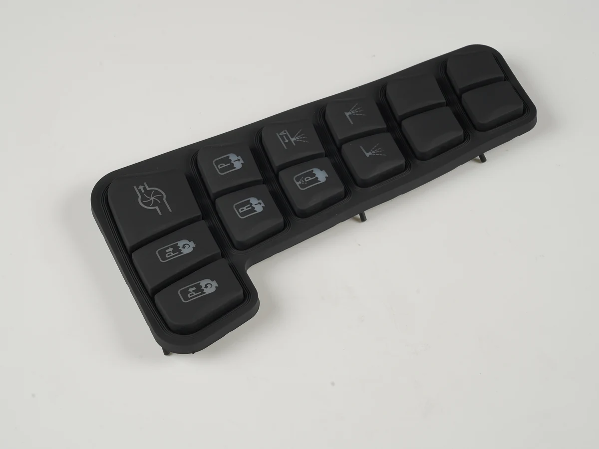
Rugged silicone rubber keypads for military equipment are custom-molded operator interfaces designed as part of a sealed electronic assembly—not drop-in parts that become “military grade” by material choice alone. They suit radios, vehicle controls, exposed panels and portable instruments when engineers define the force-displacement curve, enclosure seal, operating temperatures, fluids, legend wear, lighting, EMI bond path and PCB contact together. The right recommendation is configuration-specific: use silicone where tactile, gloved, low-profile input and geometric sealing are valuable, then qualify the production-equivalent keypad, PCB and enclosure against a tailored life-cycle profile.
| Quick decision | Specify on the drawing or system requirement | Evidence to approve |
|---|---|---|
| Operator input | Actuation force, travel, return, overtravel, glove state and false-actuation limit | Force-displacement plots across sample count and temperature |
| Sealing | Perimeter rib, compression, hard stop, seal land, fastener pattern and cable exits | Assembly-level ingress report on production-equivalent hardware |
| Temperature | Storage and operating limits, ramp/dwell, powered state and recovery | Functional data before, during and after exposure |
| Fluids | Named fluid, concentration, temperature, dwell and cleaning/recovery process | Dimensional, hardness, appearance and functional change |
| Legends | Ink/paint stack, coating, wear medium, load and readability criterion | Coupon data correlated with molded-key cycling |
| Lighting | Color, luminance, uniformity, dimming, leakage and NVIS applicability | Optical report in the installed stack |
| EMI | Conductive layer, seam, bond path, termination and enclosure interface | Equipment-level emissions/susceptibility evidence |
| PCB contact | Pill material and size, pad geometry/finish, thresholds and debounce | Resistance distribution and switch-waveform captures |
OEM teams sourcing silicone rubber keypads should treat this table as a requirements map, not a catalog of universal values.
Ruggedness Belongs to the Keypad–PCB–Enclosure Assembly
A silicone keypad is rugged only when its molded geometry, contact system, PCB and enclosure continue to function together after the specified environment. Silicone can combine a flexible key web, return spring, perimeter seal and light-management features in one molding. That integration removes joints, but it does not remove interface risk.
The functional stack usually contains:
- Keytops, legends and flexible webs that carry the load, set the force curve and restore the key.
- Light-control layers such as translucent silicone, opaque paint, blockers or a light guide.
- Conductive contacts under each key, or plungers that actuate PCB-mounted metal domes.
- A perimeter seal compressed against a controlled enclosure land.
- PCB pads and electronics that detect closure and reject bounce.
- A bezel, fasteners and housing that establish compression and protect the seam.
The Silicone Rubber Keypad Design Guide provides foundational geometry context. For military equipment, that geometry must match the platform. Web shape and bezel preload can change stiffness, fatigue stress and contact clearance; too little seal compression can leave a leak path. Durometer alone cannot settle these interactions: ASTM D2240 defines hardness as an empirical indentation measurement, not key actuation behavior.
How to Specify Rubber Keypads for Military Operators: Force and Travel
Specify force and travel as a complete curve under defined conditions; one nominal force cannot cover bare fingers, arctic mittens, vibration and accidental contact. Identify initial resistance, tactile break, electrical make, overtravel and return, with limits beyond peak force.
MIL-STD-1472H is a useful human-engineering input, not a ready-made keypad drawing. Its keyboard criteria span 0.25 to 4 N of resistance and 0.8 to 6.3 mm of displacement across covered keyboard categories and conditions; it also gives separate criteria for vehicle applications. The wide span is the point: key function, input type and handwear change the appropriate target. A Molex rubber-keypad catalog likewise shows how configurable the technology is, listing 20–500 gf actuation (about 0.20–4.90 N) and 0–5 mm stroke across its assembly range. Those figures describe a supplier portfolio, not one acceptable military design.
An engineering specification should state:
- operator posture, handwear and allowable activation time;
- measurement probe, speed, load point and temperature;
- actuation, contact-make, return and overtravel limits;
- permitted variation and installed bezel preload;
- performance after thermal, fluid and mechanical conditioning.
Low force can reduce fatigue but raise the risk of vibration-induced or incidental actuation. High force can improve discrimination yet slow repeated entry and become unacceptable with cold-stiffened material. Prototype approval therefore needs representative operators and the real bezel, PCB and gloves—not a loose keypad pressed by hand.
Sealing Must Be Proven at the Enclosure, Not Claimed by the Loose Keypad
An IP code applies to the protection provided by an enclosure, so a loose silicone molding is not independently “IP67.” IEC 60529 classifies enclosure protection against access, solid objects and water. The result depends on the assembled seam, housing, fasteners, connectors, vents and test orientation as well as the rubber component.
A defensible seal starts with a continuous perimeter feature and a flat, stiff mating land. Compression stops prevent fasteners from over-crushing the rib; spacing must close local gaps without bowing the bezel or preloading key webs. Keep parting lines, gates, ejector marks and uncontrolled texture off the seal land.
Ingress tests need a failure definition. “No visible water” is inadequate when a droplet can bridge a high-impedance input. State the permitted moisture, electrical checks, key function, recovery time and inspection method.
MIL-STD-810H covers environmental tailoring and includes rain, humidity, sand and dust, salt fog and immersion methods, but its official scope says it does not impose one universal test specification. The system life-cycle profile selects applicable methods, procedures and severities. An IEC 60529 result and a tailored MIL-STD-810 result answer different questions; one should not be presented as a substitute for the other.
Temperature and Fluid Resistance Are Compound-Specific Decisions
“Silicone” does not establish an operating range or chemical-resistance claim. Compound formulation, cure, pigment, conductive insert, coating, adhesive, PCB and enclosure materials all constrain the assembly. Storage limits must also be separated from powered operation, because electrical thresholds, lighting output and return time matter only in the functioning system.
WACKER lists one moldable grade, ELASTOSIL LR 3005/60 A/B, at 60 ± 3 Shore A and -55 °C to +210 °C, with added guidance above 180 °C. Those are grade data, not a rating for a painted, contact-equipped assembly. Finished keys still need cold force/return checks and heat aging. ASTM D573 supports comparative air-oven aging but warns that results may not correlate exactly with service.
Parker's ORD 5700 handbook states that fluorosilicone (FVMQ) improves fuel and mineral-oil resistance relative to VMQ while giving up some hot-air resistance. An elastomer-family label is not approval. Specify every fuel, hydraulic fluid, decontaminant, cleaner or salt solution that can reach the interface.
ASTM D471 provides a controlled way to compare changes in mass, volume, dimensions, hardness and mechanical properties after liquid exposure, including finished articles. It explicitly produces comparative data rather than a direct service-life prediction. Add keypad-specific checks: seal compression, legend adhesion, web cracking, tactile curve, contact resistance and electrical function after the defined dwell and recovery.
Legends and Lighting Need a Mission-Specific Wear and Optical Plan
Legends remain acceptable only when the chosen marking stack survives the real abrasion, fluids, cleaning and illumination duty. A printed legend under a protective coating can support detailed graphics. Laser ablation through an opaque topcoat can expose a translucent layer for backlighting. Multi-color molded features reduce dependence on surface ink but add tooling and geometry constraints. Hard caps can provide a different feel and wear surface, yet introduce joints and retention risks.
| Legend construction | Main advantage | Primary risk | Evidence to request |
|---|---|---|---|
| Printed ink with clear protective coat | Fine symbols and flexible color selection | Coating wear, edge lift or chemical attack | Layer specification plus rub and fluid data |
| Laser-ablated opaque paint over translucent silicone | Backlit characters with controlled light exit | Paint-thickness variation and light leakage | Day/night contrast, uniformity and abrasion after conditioning |
| Molded-through contrasting feature | Legend does not rely only on surface ink | Tool complexity and minimum feature limits | Molded samples, dimensional study and readability test |
| Hard cap or insert | Distinct surface and potential wear benefit | Bond, retention, seam and impact failure | Pull/retention, cycling, impact and sealing evidence |
ASTM D4060 measures organic-coating abrasion on a plane, rigid surface. A flat coupon can compare coating systems, but it does not reproduce a curved compliant key, glove grit, fingernail contact or field cleaning. Correlate coupon screening with part-level cycling and define failure by lost area, contrast, symbol recognition or light leakage.
Lighting requirements should state ambient range, viewing angle, color, luminance, uniformity, dimming and spill between keys. MIL-STD-3009 applies to aircraft lighting used where NVIS are employed and does not contain general lighting requirements. Do not label every military keypad “NVIS compatible”; derive applicable limits from the contract and verify the installed stack. See HMI Hardware for Aerospace and Flight Deck Equipment for related context.
EMI Control and PCB Contact Must Be Designed as One Electrical Interface
EMI shielding succeeds only when a conductive element has a low-impedance, repeatable termination to the enclosure or designated reference structure. Conductive silicone, a printed conductive layer, foil or mesh can cross the keypad area, but a shield that stops at an unbonded edge is only a floating conductor. The seam, fastener spacing, coating removal, corrosion control and bond path belong on the assembly drawing. EMI Shielding for Silicone Rubber Keypads covers this interface in greater depth.
MIL-STD-461H covers DoD equipment and subsystems and should not be directly applied to modules inside an enclosure. MIL-STD-464D addresses system-level electromagnetic environmental effects. Coupon screening is useful, but contractual evidence must use the production enclosure, cables, grounding, electronics and keypad configuration.
The contact side needs equal control. Common choices include carbon pills, lower-resistance conductive pills, metal-bearing contacts and silicone plungers over metal domes. None is universally best.
| Contact approach | Useful characteristic | Design concern | Verification focus |
|---|---|---|---|
| Standard carbon pill | Established low-current keypad closure | Resistance distribution and contamination | Resistance at initial, conditioned and cycled states |
| Lower-resistance conductive pill | More margin for tighter input thresholds | Material/cost trade and pad compatibility | Distribution, drift and current/voltage boundary |
| Metal-bearing pill | Lower resistance can be available | Wear, galvanic/material compatibility and cost | Pad finish, debris, cycling and environmental exposure |
| Plunger over metal dome | Crisp snap and separate contact element | Dome registration, preload and dome fatigue | Alignment, force curve, bounce and cycling |
Specify pill size/location, PCB pad pattern/finish, misregistration, current/voltage, bias network, logic thresholds and contamination limits. Measure a population rather than one golden sample. Molex lists <200 Ω resistance and <5 ms bounce across its catalog offering—portfolio data, not universal limits.
Texas Instruments notes that contact bounce can range from hundreds of microseconds to tens of milliseconds by construction. Capture both edges at temperature and after conditioning, then set hardware or software debounce from measured distributions. A folklore value can double-count a press or add latency.
Application-Risk Matrix: Match Each Hazard to a Failure Mechanism and Proof
A military keypad risk matrix should connect the mission exposure to a specific failure path, design control and acceptance record. Listing “shock, water, temperature” without these links does not produce a qualification plan.
| Application hazard | Likely keypad/interface failure | Design response | Qualification evidence |
|---|---|---|---|
| Cold operation with gloves | High force, slow return, missed entry | Tune web geometry; enlarge or separate keys; control preload | Force curve and task trial at cold operating condition |
| Vehicle vibration | False actuation, fretting or intermittent contact | Set force margin; stabilize PCB and bezel; validate debounce | Powered vibration with event logging and post-test inspection |
| Wind-driven rain / washdown | Perimeter or fastener leak | Continuous rib, flat land, compression stops and controlled torque | Assembly-level ingress test with electrical checks |
| Blowing dust / sand | Web abrasion, blocked travel or contact contamination | Guard gaps, drain/shedding geometry and sealed contact zone | Tailored dust exposure plus force/contact measurements |
| Fuel or hydraulic-fluid splash | Swelling, softening, coating loss | Select compound and coating from named fluid list | ASTM D471-style exposure plus dimensional and functional data |
| Solar and thermal aging | Hardness shift, cracks, color or legend change | Compound, pigment and coating screening | Material aging plus finished-key function after exposure |
| Repeated cleaning | Legend fade or edge lift | Compatible ink/coating or molded legend | Defined cleaner, wipe medium, load and readability limit |
| High RF field / onboard transmitters | False key events or equipment upset | Continuous shield/bond path and protected input circuit | Applicable MIL-STD-461 equipment-level report |
| Night / NVIS use | Hot spots, leakage, poor contrast or NVIS interference | Optical stack, blockers, dimming and tailored emission limits | Installed optical measurements at specified settings |
Military Use Cases Change the Design Priority
The same molded technology supports different military equipment only after the dominant risk is identified.
Dismounted communications and handheld controllers
Gloved discrimination, rain, grit, cold return and low-power lighting dominate. Raised borders or spacing can reduce adjacent-key errors, while powered drop and vibration tests should log false events.
Ground-vehicle controls
Vibration, incidental contact, fuels, sunlight and connectorized electronics shape the design. Evaluate force margin and debounce while powered; EMI evidence must include the enclosure bond and cables.
Exposed naval or shore equipment
Salt, wet-dry cycling, cleaners and corrosion at shield or fastener interfaces can govern life. Control perimeter, mounting and cable-entry leakage, material compatibility and drainage on drawings.
Aircraft crewstation equipment
Lighting, viewing angle, dimming and emission control become central when NVIS is in scope. MIL-STD-3009 applies only to the defined aircraft NVIS lighting environment; it does not replace general lighting, human-factors, environmental or EMC requirements.
Portable maintenance and test equipment
Transport, bench chemicals, cable strain and uncontrolled weather may dominate. A replaceable module helps service, but each connector and service seam joins the sealing and EMC configuration.
Qualification Evidence Must Match the Delivered Configuration
Move qualification from material screening to a production-equivalent assembly, with pass/fail criteria written first. “MIL-STD-810 tested” without revision, method, procedure, severity, configuration, powered state and results cannot establish suitability. MIL-STD-810H requires life-cycle tailoring.
A practical sequence is:
- Screen materials and constructions. Compare candidate compounds, coatings, legends, contacts and shield terminations using controlled coupons or subassemblies.
- Approve functional prototypes. Measure force curves, contact distribution, lighting and seal compression in the intended enclosure. Use Silicone Rubber Keypad Prototype Approval to structure the decision record.
- Freeze the qualification configuration. Record material designation, cure, color layers, contact, coating, PCB revision, housing, fasteners, torque, cable set, firmware and debounce.
- Run tailored environments with functional monitoring. Select relevant MIL-STD-810 methods and contractual severities; combine or sequence exposures when the life-cycle rationale requires it. Coordinate the evidence through testing and validation planning.
- Inspect and remeasure. Repeat force, travel, return, contact, leakage, optical and shield-bond checks. Disassemble selected units to locate hidden moisture, wear, cracks or debris.
- Control changes. Evaluate whether a compound, pigment, coating, conductive insert, PCB finish, enclosure or firmware change invalidates prior evidence.
The package should include controlled drawings, material declarations, traceability, calibrated-equipment records, raw distributions, photographs, anomalies, deviations and signed results. A certificate without test configuration is weak evidence. Preserve qualification and production characteristics during prototyping and sample approval.
When a Silicone Keypad Is Not the Right Interface
Silicone is not the default for long-travel typing, high-speed data entry, a reconfigurable display or direct power switching. A sealed switch, full-travel keyboard, guarded control, rotary selector or touch display may fit better.
It is also a poor choice without a controlled seal land, adequate depth, a fluid-compatible construction or assembly-level qualification. Use a distinct guarded control for safety-critical or emergency functions.
Frequently Asked Questions
What makes rubber keypads for military equipment rugged?
Rubber keypads for military equipment become rugged through assembly design: tuned key webs, controlled contacts, a compressed perimeter seal, durable legends, an appropriate optical stack, a terminated EMI path and a compatible PCB/enclosure. The production-equivalent assembly must then pass the project's tailored environmental, human-factors and electrical acceptance criteria.
Can a silicone rubber keypad itself have an IP67 rating?
No loose keypad establishes an IP67 enclosure rating by itself. IEC 60529 classifies protection provided by an enclosure, so the result depends on the keypad, bezel, seal land, compression, fasteners, housing, connectors and vents in the tested configuration. Ask for the assembly report, orientation, acceptance checks and exact hardware revision.
Does passing MIL-STD-810 make a keypad “military grade”?
Not without the test details. MIL-STD-810H is a tailoring framework, not one universal certification. Evidence must name the revision, method, procedure, severity, duration, configuration, powered state and pass criteria derived from the equipment life cycle. A bare keypad result cannot automatically qualify the installed HMI assembly.
What actuation force and travel should a military keypad use?
There is no single correct force or travel. MIL-STD-1472H spans 0.25–4 N resistance and 0.8–6.3 mm displacement across covered keyboard categories and conditions. Select targets from function, glove state, posture, vibration and error risk, then approve the complete force-displacement curve at operating temperatures and installed preload.
When should fluorosilicone replace standard silicone?
Consider FVMQ when the named exposure includes fuels or mineral oils that standard VMQ cannot tolerate. Parker documents improved fuel and mineral-oil resistance for FVMQ but poorer hot-air resistance than VMQ. Confirm the exact compound with specified fluid, temperature, dwell and recovery tests; do not approve by polymer family alone.
How should military keypad legends be qualified?
Qualify the actual ink, paint, coating or molded legend after the specified fluids, cleaning and climate exposure. ASTM D4060 can compare coatings on flat rigid coupons, but curved silicone keys need correlated part-level rubbing and cycling. Define the abrasive medium, load, cycles, readable-area or contrast limit, and backlight-leakage criterion before testing.
How is EMI shielding verified around a silicone keypad?
Verify the complete conductive path from the keypad-area shield through the seam and termination into the enclosure reference structure. MIL-STD-461H applies at equipment or subsystem level, while MIL-STD-464D addresses system-level E3. Coupon shielding data can screen materials, but it cannot replace testing with the enclosure, cables, electronics and grounding configuration.
What inputs should an OEM send for a custom military keypad review?
Send the 3D model, bezel and seal land, force/travel target, glove and temperature conditions, legend method, lighting and NVIS requirements, PCB contact pattern and finish, electrical thresholds, fluid list, EMI bond concept, qualification profile, annual and lifetime quantity, and the acceptance evidence required by the contract.
Project-Input Checklist for Drawing and RFQ Review
Before tooling, provide:
- 3D model and 2D drawing with datums and tolerances;
- key map, force-displacement targets, overtravel, preload and operator/glove conditions;
- bezel, seal land, compression stop, fastener pattern and enclosure material;
- compound, storage/operating temperatures and named fluids;
- legend artwork, color/contrast criteria, coating or molded method and wear acceptance;
- LED layout, optical targets, dimming and applicable NVIS requirement;
- conductive contact material/size, PCB pattern/finish, current/voltage and debounce approach;
- shield layer, termination, enclosure bond and applicable EMI/E3 requirements;
- qualification profile, configuration control, quantity and evidence package.
Teams can send drawings for engineering review with the 3D model, force/travel target, legend method, PCB contact pattern and quantity. When the requirements and evidence package are defined, request an engineering quote for the production-intent configuration.
References
- DLA ASSIST, MIL-STD-810 environmental tests, Revision H Change 1, May 18, 2022.
- DLA ASSIST, MIL-STD-1472 human engineering, Revision H; validated April 10, 2026.
- DLA ASSIST, MIL-STD-461 equipment EMI, Revision H, April 17, 2026.
- DLA ASSIST, MIL-STD-464 system E3, Revision D; validated February 9, 2026.
- DLA ASSIST, MIL-STD-3009 aircraft NVIS lighting, active document dated April 4, 2024.
- International Electrotechnical Commission, IEC 60529: Degrees of Protection Provided by Enclosures, Edition 2.2, August 29, 2013.
- ASTM International, ASTM D2240: Rubber Property—Durometer Hardness, D2240-15(2021).
- ASTM International, ASTM D471: Rubber Property—Effect of Liquids, D471-16a(2021).
- ASTM International, ASTM D573: Rubber—Deterioration in an Air Oven, D573-04(2025).
- ASTM International, ASTM D4060: Abrasion Resistance of Organic Coatings by the Taber Abraser, D4060-25.
- Parker Hannifin, O-Ring Handbook ORD 5700, accessed August 24, 2026.
- WACKER Chemie, ELASTOSIL LR 3005/60 A/B data, accessed August 24, 2026.
- Texas Instruments, SLVA091 switch-debounce report, accessed August 24, 2026.
- Molex, Rubber Keypad Assemblies, Order No. 987650-3744, May 2012.
Bring the drawing, stack and operating conditions
JASPER engineering will review the interfaces, open risks and evidence required for a production quote.