
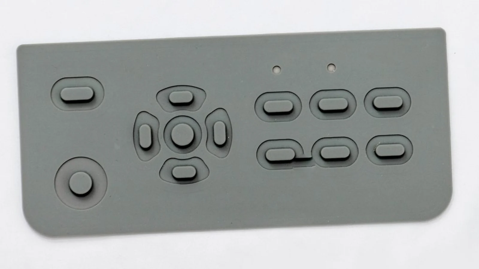
A silicone rubber keypad prototype is ready for production review only when it proves the released geometry, force curve, electrical action, decoration, lighting, and fit in the intended assembly. This guide gives OEM engineering, quality, and sourcing teams a ten-point approval method. It does not treat a visual sample, a 3D-printed form model, or compliance with ISO 3302-1:2014 as automatic approval of the mold or production process.
1. Why a Good-Looking Sample Can Still Fail Production
A keypad can look correct on a desk and fail when the enclosure screws are tightened. A contact may sit over the PCB pad in free state but shift under installed preload. A legend may look even under room light but leak light around its mask when powered. A key may feel crisp in one hand-held sample yet show a different peak force when the test speed, support plate, sample age, or cavity changes.
Those failures share one cause: the sample was approved without defining what kind of evidence it represented.
| Approval object | What it can decide | What it cannot decide by itself |
|---|---|---|
| Form model | Key layout, reach, spacing, label hierarchy, gross enclosure clearance | Mold shrinkage, web collapse, flash, production texture, electrical closure, or repeatability |
| Molded engineering sample | Initial molded geometry, demolding behavior, contact position, early force curve | Final graphics, powered lighting, production capability, or an untested material/process change |
| First article | Conformance of traceable samples to a controlled drawing and inspection plan | Future-lot stability or any feature omitted from the inspection plan |
| Golden sample | A protected visual or tactile reference under defined conditions | Numerical dimensions, force limits, artwork files, electrical criteria, test methods, or change control |
| Production approval | Released product definition, tool revision, material/process route, inspection, traceability, and change rules | Performance outside the validated assembly, environment, duty cycle, or regulatory scope |
The distinction matters because rubber measurement is condition-sensitive. measuring-foot pressure can materially change the observed thickness of soft, flexible materials. A sample record that omits measurement pressure, fixture, state, age, and location can create a disagreement that looks like a tool error even when the two laboratories are simply measuring differently.
Production release is therefore a chain of linked approvals, not a signature on one attractive part. The chain begins with controlled inputs, passes through tool and sample evidence, and ends with a configuration that another lot can reproduce and inspect without relying on memory.
2. How to Approve a Silicone Rubber Keypad Prototype: The 10-Point Framework
The ten approval points are interface definition, molding/tool strategy, shrinkage, mold concept, dimensions, force curve, electrical action, graphics and lighting, assembly fit, and traceability. They are ordered by dependency: a downstream test should not compensate for an upstream definition that is still moving.
2.1 Freeze the complete interface, not just the rubber outline
The tool input must describe the complete force and signal path. At minimum, freeze matching 2D and 3D revisions; functional datums; key centers and top geometry; web and base sections; conductive element or actuator; PCB contact map; enclosure guides and hard stops; seal lands; fasteners; connector; artwork; lighting architecture; and the boundary of what the supplier will deliver. The related silicone rubber keypad design guide should own detailed geometry design; this article owns the decision to release that design into tooling.
Finger or specified actuator
Keytop + legend + protective coating
Silicone web / return structure
Carbon pill, metal pill, dome, or separate switch actuator
PCB or circuit contact + local support
Housing guides + hard stops + fasteners + sealing interface
Each layer changes the measured result. A flexible PCB without its production support can shift contact travel. A bezel can rub a tall key. A housing stop can hide excessive overtravel or preload the web. The N&H silicone keypad design guide likewise treats the key, web, contact, PCB, bezel, stabilizer, and air path as one working structure.
One released interface package identifies every mating revision, datum, supplied item, and validation owner.
The mold is released from a cosmetic top view while the PCB, housing stop, contact map, or connector is still “close enough.”
2.2 Approve the molding route, tool strategy, ownership, and change path
"Silicone tool" is not a complete process definition. WACKER's material and processing guide separates compression, transfer, and injection molding and documents different handling requirements for solid and liquid silicone. Saint-Gobain makes the practical change-control point explicit: moving from HCR to LSR can alter the tool architecture, parting line, vents, gates, and secondary operations. A successful HCR prototype does not silently qualify an LSR production route.
Tool material also affects correlation. Saint-Gobain's aluminum and steel differ in hardness and thermal conductivity; cure time, shrinkage, and molding behavior may therefore differ between an aluminum prototype tool and a steel production tool. If the program changes tool material, the approval plan should identify which evidence must be repeated.
Before irreversible work, record the molding route, prototype and production tool materials, cavity concept, replaceable or steel-safe features, tool ownership, storage and maintenance responsibility, correction allowance, and authority to approve changes. Tool ownership without revision rights is not real configuration control.
The purchase package links tool number, tool material, process route, cavity plan, ownership, correction rules, and revalidation triggers.
A supplier promises that a soft prototype tool is “production equivalent” without a written correlation plan.
2.3 Control shrinkage as a measured trial, not a copied constant
Silicone shrinkage is a material-and-process outcome. WACKER reports approximately 2–4% linear shrinkage for its reference silicone data and says the result depends strongly on grade and processing parameters; precision parts need preliminary trials. Shin-Etsu's Silicone Rubber for Molding gives a narrower about 2–3% LIMS example at 100–150°C. Neither range is a universal rubber keypad factor.
The defensible workflow separates a starting assumption from measured evidence and the correction decision:
| Gate | Controlled input or evidence | Decision rule |
|---|---|---|
| Initial tool assumption | 3.0% initial example—inside WACKER's 2–4% band and at the upper boundary of Shin-Etsu's 2–3% example | Confirm before tool release using the selected grade, cure route, toolmaker calculation, and measurement state |
| First-shot measurement | Parts identified by tool, cavity, material lot, process record, cure/post-cure state, age, and measurement method | Compare patterns by axis, section, feature family, and cavity; do not treat one point as the whole tool |
| Root-cause review | Free-state dimensions, assembly fit, force curve, fill/flash evidence, and measurement-system check | Separate global scale error from local flow, demolding distortion, fixture pressure, or enclosure preload |
| Correction release | Marked drawing, cavity/tool revision, approved change, and repeat-test list | Change steel, process, drawing, mating part, or method only when the evidence identifies the controlling cause |
The 3.0% value above is deliberately concrete so an editor cannot mistake a blank field for approval. It is supplier reference data and not a value to machine from. If the selected material/process evidence supports a different factor—or different factors by direction or feature—the tool calculation must follow that evidence.
The first-shot report connects shrinkage findings to material, cavity, process, conditioning, measurement, and a signed correction record.
A universal percentage is copied into CAD, then every out-of-tolerance feature is blamed on “rubber variation.”
2.4 Review initial, parting line, feed, vents, flash, and demolding together
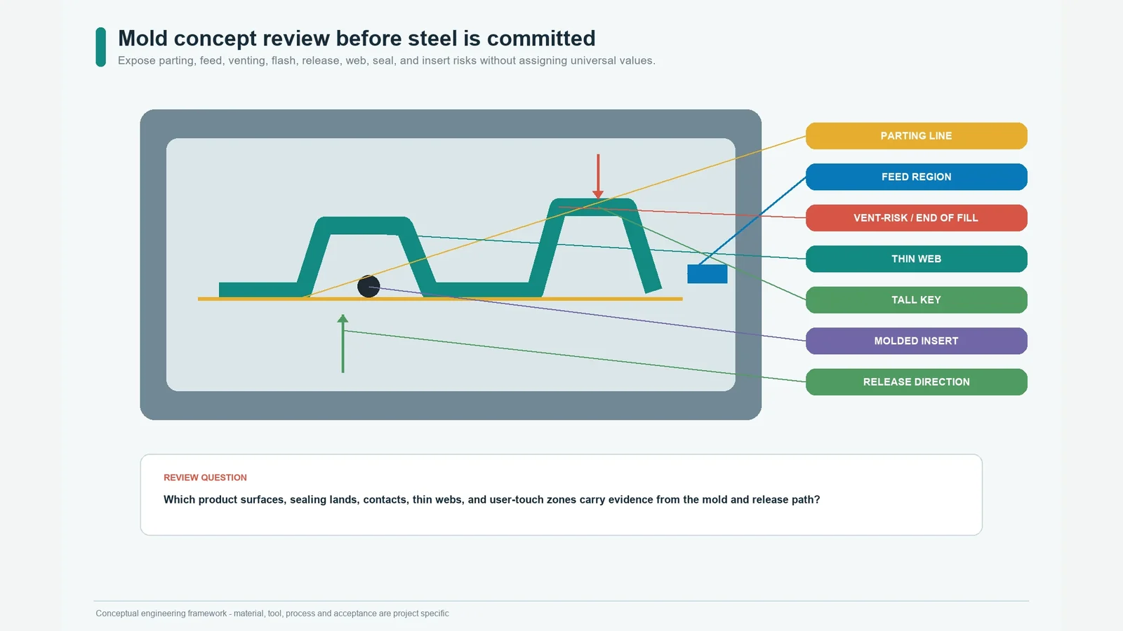
The mold-concept review should mark every witness and release feature on the product model. Parting lines can affect cosmetics, sealing lands, key motion, and flash. Gates or charge locations can affect visible surfaces and flow. Vents belong at likely trapped-air or end-of-fill regions, but their design depends on the selected process. Demolding can stretch thin webs, pull inserts, or mark a coated surface.
Protolabs publishes useful—but supplier-specific—LSR initial examples: 0.5° for vertical faces, 2° for most situations, 3° for shutoffs and its PM-T1 light texture, and 5°+ for its PM-T2 texture. Shallow features with no initial release angle can be reviewed case by case. Those values demonstrate why a single initial angle is inadequate; they do not establish JASPER or project rules.
| Tool feature | Approval question | Failure if omitted |
|---|---|---|
| Parting line | Where will the line and permissible flash sit relative to seals, contacts, visible faces, and moving webs? | Leakage path, rubbing, cosmetic step, or trim damage |
| Gate or charge location | Where does material enter or sit, where can flow fronts meet, and which surface carries the witness? | Visible vestige, local fill issue, knit/flow mark, or dimensional disturbance |
| Vent / overflow | Which thin webs, tall keys, recesses, or end-of-fill regions can trap air? | Short fill, burn/scorch evidence, void, or unstable flash |
| initial and release | What initial map matches depth, texture, undercut, tool split, and removal direction? | Web stretch, tearing, insert pull, or surface marking |
| Flash and trim | Where is flash permitted, how is it measured, and what removal route is allowed? | Interference, inconsistent appearance, or a damaged sealing/functional edge |
| Cavity identification | How will samples remain attributable when a visible cavity mark is unacceptable? | Mixed evidence and no cavity-specific correction path |
SIMTEC's LSR mold-design guide supports the gate/vent boundary: both can affect flash, and a gate witness should be kept off dimensionally or aesthetically critical surfaces where the design permits. The OEM should approve the affected product areas; the toolmaker should own the detailed process solution.
A marked-up tool review shows line, feed, vent, flash, trim, release, insert, and cavity-traceability decisions against functional surfaces.
The only mold review artifact is an external keypad rendering with no split, witness, or demolding information.
2.5 Classify dimensions and define the measurement state
Rubber drawings need functional hierarchy. ISO 3302-1:2014 defines dimensional tolerance classes for solid molded rubber, while ISO 3302-2:2022 addresses geometrical controls such as flatness, parallelism, perpendicularity, coaxiality, and position. The standards do not decide which keypad feature controls contact registration, sealing, or user feel. The drawing must do that work.
| Dimension class | Examples | Evidence to approve |
|---|---|---|
| Assembly interface | Outer profile, locators, bosses, seal lands, connector clearance | Datum-based report plus fit in the released housing |
| Switching geometry | Web section, contact height, rest gap, travel, hard-stop relationship | Section measurement plus force/electrical test in the defined support stack |
| Contact registration | Key center, pill center, PCB pad relationship | Positional review at worst-case stack and functional closure |
| Optical / graphic | Legend, mask, light window, coating boundary | Artwork overlay and powered visual inspection under fixed conditions |
| Cosmetic | Texture, gloss, parting line, gate witness, trim area | Named view zones, lighting, distance, defect size, and reference method |
| Reference only | Non-functional envelope or process-reference dimensions | Mark as reference; do not spend correction budget as if it controlled function |
Record whether each measurement is free-state or assembled, the time after molding or post-cure, conditioning, fixture/support, instrument, contact geometry and force, locations, sample quantity, cavity, and data resolution. ISO 23529:2016 covers preparation, storage, conditioning, and timing concepts for rubber testing, while expressly leaving special whole-product requirements to the applicable method. ASTM D3767 adds the warning about instrument pressure. Together, they support a controlled method—not a generic “inspect to drawing” note.
Critical dimensions carry datums, state, method, sample plan, and an acceptance owner; ISO class references are contractual and edition-controlled.
Every dimension uses one blanket tolerance even though soft sections, contact position, seal geometry, and cosmetic features serve different functions.
2.6 Approve the complete force-displacement curve and return path
Key feel needs named quantities. N&H defines F1 as actuation force, F2 as mechanical contact force, F3 as return force, and F4 as over-stroke force; its diagram also identifies peak travel S1, contact stroke S2, and electrical-contact stroke S4. The familiar snap-ratio calculation is:
Snap ratio (%) = (F1 − F2) / F1 × 100
A ratio alone is not approval. A stronger force drop can reduce restoring force F3 and contribute to a sticking key. The record should therefore include the press and return curves, electrical switch point, bottoming region, incomplete return, and any rubbing. It should also name the actuator tip, press location and direction, speed, PCB/support fixture, sample age, conditioning, cavity, and repeat count.
For an editable starting point, Diamond HMI's Rubber Keypad Design Guide 2021 recommends 125–150 gf actuation and 40–60% snap for a common tactile design, with roughly 30–35 gf return force. This package selects a mid-to-upper initial example of 150 gf peak (about 1.47 N), 50% snap ratio, and 35 gf minimum return (about 0.34 N). These are not JASPER specifications, do not predict life, and must be replaced with application targets and measured tolerances before tool release.
ASTM D2240-15(2021) does not close this gap: it controls indentation hardness measured with a durometer. Shore hardness can help control material, but it cannot substitute for the assembled key's force-displacement curve.
Curves and electrical events are tied to the released PCB/support/housing fixture, method, cavity, conditioning, and acceptance bands.
Approval says only “soft,” “firm,” or “good click,” or it replaces a force curve with one Shore A value.
2.7 Approve electrical closure in the intended mechanical stack
Electrical action must be measured where the product will sense it. The test plan should name the circuit nodes, open-state criterion, applied test voltage/current or sensing circuit, contact point on the travel curve, closed-state limit, stability through overtravel, release point, and any bounce or intermittent-event limit. The current PCB finish, pad geometry, local support, connector, firmware scan method, and installed compression all belong to the result.
A loose carbon-pill test can isolate one variable, but it cannot prove closure in a housing that shifts the key or flexes the PCB. Conversely, a failing assembled test should not trigger a mold correction until the team separates contact registration, PCB support, pad design, preload, contamination, and measurement logic. Detailed carbon and pad acceptance belongs in the planned carbon-pill resistance guide; this tooling guide keeps the focus on reproducible alignment and configuration.
The report overlays F1/F2/F3/F4, S1/S2/S4, and the electrical make/break points for the released mechanical and electrical revisions.
A continuity beep on an unsupported bench sample is accepted as proof of production electrical performance.
2.8 Approve legends, coatings, color, and powered backlighting as separate evidence
A first molded shot approves no finished artwork. The decoration record should identify the base silicone color reference, ink or paint system, coating stack, texture/gloss reference, artwork revision, print or laser route, mask geometry, legend position, and inspection zones. If durability matters, the plan must name the actual abrasion, cleaner, UV, temperature, sweat, oil, or disinfectant exposure and the pass/fail observation. A universal “wear-resistant” label is not a test.
N&H documents several distinct constructions: positive or negative printing, PU/epoxy/silicone coatings, laser-opened legends, center or side LEDs, electroluminescent sources, and light-guide integration. Each architecture creates different approval objects. The planned laser legend and coating guide can own detailed surface validation; this prototype must still carry the correct artwork and process revision.
Backlighting requires a powered assembly. Record the LED and PCB revision, supply condition, ambient-light level, viewing angle/distance, camera or photometer method, and acceptance zones for hot spots, dim legends, leakage, cross-talk, pinholes, and unlit appearance. Day-view color approval does not approve night-view light control.
Molded color, decorated appearance, surface durability, and powered optics have separate records tied to one configuration.
An unpowered painted sample is called “backlight approved,” or the laser artwork changes after the approval photograph.
2.9 Approve enclosure fit, preload, sealing, and handling in the final assembly
Install the keypad with the released housing, PCB, fasteners, gasket/adhesive, connector, spacers, and support. Check locator engagement, edge curl, key-to-bezel clearance, installed preload, off-axis rubbing, full return, hard-stop timing, PCB deflection, connector strain, seal compression, and service access. Repeat the force/electrical check after assembly; a pass in free state is not evidence that the installed stack is neutral.
For an industrial-control interface, the approval plan may also need gloves, contamination, vibration, cleaning, cable routing, and maintenance access. Use that application route to frame gloves, contamination, vibration, cleaning, cable routing, and maintenance access.
IEC 60529 classifies protection provided by electrical enclosures. It does not turn a loose keypad into an IP-rated product. If the finished equipment requires an IP Code, test the final enclosure construction—including keypad flange, fasteners, adhesive/gasket, cable entries, housing joints, and aging state—under the applicable edition and project conditions.
For a medical, automotive, or other regulated program, component manufacturing evidence remains separate from finished-device validation and regulatory approval. The OEM owns the final use, hazard analysis, system validation, and submission boundary unless a contract assigns specific work elsewhere.
2.10 Lock traceability before approving the sample
Every result must point back to a reproducible configuration. Record tool number and revision; cavity or cavity family; material manufacturer/grade and lot; pigment/color system; conductive insert lot; molding date/run and process route; cure/post-cure state; deflash, wash, print, coat, and laser route; PCB, housing, firmware, and assembly revisions; inspection record; deviation status; and sample disposition.
Cavity identity need not be a visible mark on the customer surface. Separated packaging, runner position, fixture location, or another controlled mapping can preserve traceability. The method matters less than the ability to find which cavity produced which curve and dimension report.
The approval matrix below connects each object to its minimum evidence. It complements JASPER's quality and testing framework without claiming that JASPER currently performs every listed method.
| Approval object | Minimum test state | Record required | Release boundary |
|---|---|---|---|
| Molded dimensions | Free state at defined age/conditioning; identified cavity | Datum report, instrument/contact method, sample count, drawing/tool revision | Geometry only; not assembled force or seal |
| Force and return | Released PCB/support/housing fixture; defined actuator and speed | Press/return curves, F1–F4, S1/S2/S4, electrical event, cavity/repeats | Defined key groups and fixture only |
| Electrical action | Released circuit, sensing condition, contact geometry, and support | Open/closed limits, make/break travel, stability/bounce where required | Specified electrical load and firmware boundary |
| Legends and coating | Final material color, artwork, ink/paint/coating stack | Color/visual method plus project abrasion/cleaner/exposure result | Tested stack and exposure only |
| Backlighting | Powered final PCB/LED/keypad/housing stack | Supply, ambient, angle, zones, luminance or approved visual record | Tested optical configuration only |
| Assembly fit | Final housing, fasteners/torque, PCB, spacers, gasket/adhesive, connector | Fit, preload, rubbing, return, stop, deflection, seal-compression observations | Released mating revisions only |
| Environmental / ingress | Production-intent complete assembly | Applicable method, conditioning, duration, sample count, result, post-test checks | Finished assembly and stated rating/test scope |
| Production release | Released tool/material/process/secondary operations and inspection plan | Approval signatures, deviations, golden sample control, change triggers | No unreviewed change to grade, tool, cavity, process, artwork, or mating stack |
A scanner can move from any approved sample to its tool, cavity, material, process, secondary operations, mating revisions, and raw results.
Samples are mixed in one bag and identified only as “T1,” with no cavity, material, date, or drawing revision.
When a molded silicone keypad is not the best construction
A production-intent silicone keypad is not automatically the right interface. A capacitive panel or display can be better when the product needs gestures, a changeable UI, or a continuous sealed front with no moving keys. Metal domes, tact switches, or a membrane-switch assembly can be better when the stack needs a thinner profile or a sharply defined switch element independent of a molded web. Discrete switches can be more appropriate when the electrical load, safety architecture, or serviceability requires a separately rated component.
For very low quantities while layout is still changing, standard switches beneath a machined or printed interface may also avoid premature custom tooling. The decision should follow user interaction, environment, electrical architecture, service plan, volume, validation burden, and total assembly—not the availability of a silicone sample.
3. Rubber Keypad Sample Approval: A Six-Step Buyer Process
This sequence turns the framework into controlled procurement. A gate may send the project backward; it should never be skipped because the next sample already has a delivery date.
Controlled inputs → Mold-concept review → Named prototype stage
Released correction ← Root-cause evidence ← Fixed-order inspection
Production-representative build → Release package → Change control
Step 1 — Issue one controlled input package
Send matching 2D/3D revisions, datum scheme, critical characteristics, target force curve, contact/circuit map, current PCB and housing data, supplied-item boundary, material and restricted-substance requirements, color/artwork files, coating/backlight architecture, environment, sample quantities, annual-volume basis, validation plan, and required records. Mark every initial value. The general prototyping capability can support risk reduction, but the RFQ must state which stage is required and what it may approve.
Do not let email attachments become parallel masters. The RFQ, drawing, model, artwork, and acceptance matrix need a shared revision baseline.
Step 2 — Hold the mold-concept review before irreversible work
Review process route, tool material, split/parting line, cavity strategy, feed or charge, vents, flash/trim, initial, inserts, demolding, texture, cavity identification, steel-safe features, correction allowance, ownership, maintenance, and revalidation triggers. Record unresolved items and assign each to the OEM, keypad supplier, toolmaker, PCB supplier, decorator, or assembler.
Release only the features that are stable. A mold start with an open PCB datum or housing stop is schedule movement, not risk retirement.
Step 3 — Name every sample stage and its approval limit
| Stage | Intended evidence | Explicit limit |
|---|---|---|
| Digital / DFM review | Interfaces, datums, sections, contact map, tool risk, test plan | No physical behavior |
| Non-production form model | Reach, layout, envelope, key spacing, basic housing clearance | No production shrinkage, surface, force, contact, flash, or life evidence |
| Molded engineering sample | Initial geometry, web behavior, force/return, contact position, fill, flash, release | No final artwork/light or production repeatability unless represented |
| Decorated powered assembly | Final appearance, coating, laser/print, powered light, installed force/electrical action | No production process capability or untested exposure performance |
| Production-representative build | Released tool/material/process, secondary operations, assembly, inspection, packaging | No approval beyond the tested configuration and conditions |
A custom keypad prototype made from substitute material or tooling can be valuable; its label and report must prevent it from becoming a production golden sample by accident.
Step 4 — Inspect first molded samples in a fixed order
Start with identity: drawing, model, tool, revision, cavity, material, process, and conditioning. Then inspect fill, cure, contamination, insert placement, flash, trim, and demolding damage. Measure free-state critical geometry before assembly can hide it. Next, run force/return and electrical closure in the defined fixture. Install the released housing and PCB, repeat functional checks, then add graphics, coating, lighting, environmental exposure, and packaging evidence.
This order helps distinguish a tool error from a mating-part, method, or assembly error.
Step 5 — Close deviations through evidence-led correction
Every deviation needs an owner, root-cause hypothesis, confirming evidence, action, affected characteristics, tool/drawing/process revision, and repeat-test list. Use pattern evidence: all cavities versus one cavity, X versus Y direction, thick versus thin regions, free versus assembled state, and before versus after conditioning.
Do not “tune the process” until one sample passes if the approved process window, cavity behavior, and downstream force or dimension consequences remain unknown.
Step 6 — Release production with a complete approval package
Production release should include the signed drawing/model/artwork baseline; tool and cavity record; approved material/process/secondary-operation route; dimensional, force, electrical, graphic, optical, assembly, and required environmental reports; controlled golden sample; inspection plan; packaging; deviations; change-notification rules; and revalidation triggers.
Use this compact sample-approval checklist before signing:
- [ ] Sample stage and permitted decisions are named.
- [ ] Drawing, model, artwork, PCB, housing, firmware, and tool revisions match.
- [ ] Tool, cavity, material lot, molding run, cure/post-cure, and secondary operations are traceable.
- [ ] Critical dimensions state datum, free/assembled condition, method, and acceptance.
- [ ] Press/return curves and electrical events use the released fixture and method.
- [ ] Legends, coating, color, and powered lighting each have defined evidence.
- [ ] Installed fit, preload, rubbing, return, stop, connector, and seal interfaces are checked.
- [ ] Deviations have dispositions and repeat-test requirements.
- [ ] The golden sample is protected and subordinate to controlled data.
- [ ] Production changes require notice and a defined revalidation decision.
4. Release Blockers That Stop Silicone Keypad Tooling or Sample Approval
These conditions override a good appearance, an attractive quote, or a promised launch date:
- The sample has no tool, cavity, material, or drawing identity. Its measurements cannot support a controlled correction or later comparison.
- One shrinkage percentage is presented as universal. WACKER and Shin-Etsu both show material/process dependence.
- initial, parting line, gate/charge, vent, flash, and trim locations are invisible before tooling. Functional surfaces are being accepted without reviewing mold witnesses.
- Key feel is described only with adjectives. No press/return curve, fixture, speed, conditioning, or electrical event is recorded.
- Artwork, PCB, housing, or firmware revisions differ across tests. The evidence does not describe one buildable configuration.
- A loose keypad is claimed to prove an IP Code. IEC 60529 applies to the defined enclosure, not an isolated rubber part.
- An aluminum prototype tool is declared equivalent to production steel without correlation. Thermal and wear behavior can differ.
- The golden sample is the production specification. Physical references cannot replace numerical limits, controlled files, inspection methods, and change rules.
5. Frequently Asked Questions
What should a silicone rubber keypad prototype prove before production?
A production-intent silicone rubber keypad prototype should prove traceable molded geometry, force and return, electrical action, decoration, powered lighting, and fit in the released housing/PCB stack. It should also identify the tool, cavity, material, process, conditioning, secondary operations, test methods, deviations, and configuration limits. A form model proves only the questions its substitute construction can represent.
Can a 3D-printed or cast custom keypad prototype approve production tooling?
No. A printed or cast model can approve layout, reach, labels, and gross fit, but it cannot establish production shrinkage, web collapse, flash, mold texture, cavity behavior, or the released material/process route. Use it to close early design questions, then require molded and production-representative stages for tooling and production approval.
What shrinkage value should be used for silicone keypad tooling?
Use the selected material supplier's data and the toolmaker's process-specific calculation, then correct it from traceable first-shot measurements. WACKER reports roughly 2–4% for its reference silicone data; Shin-Etsu reports about 2–3% for the cited LIMS conditions. The 3.0% example in this guide is initial, not a universal keypad factor or JASPER value.
What belongs in a rubber keypad sample approval report?
A rubber keypad sample approval report should identify the sample stage, drawing/model/artwork revisions, tool and cavity, material lot, process and cure state, sample age/conditioning, measurement method, dimensions, press/return curves, electrical results, decoration, powered lighting, assembly fit, deviations, disposition, and repeat-test requirements. Attach raw data rather than only pass/fail boxes.
How should key feel be approved?
Approve key feel with press and return force-displacement curves plus the electrical make/break points. Record F1 actuation, F2 contact, F3 return, F4 over-stroke, relevant travel positions, actuator, speed, support fixture, conditioning, cavity, and repeats. Use subjective panel comments as supplementary evidence, not the numerical specification.
When should legends, coatings, and backlighting be approved?
Approve them after the molded geometry is stable and with the final material color, artwork, ink/paint/coating stack, laser route, PCB, LEDs, housing, and supply condition represented. Keep unpowered appearance, abrasion/cleaner exposure, and powered optical acceptance as separate records. Any post-approval stack or artwork change needs a defined review.
Does a keypad prototype prove an IP rating?
No. IEC 60529 classifies protection provided by a complete electrical enclosure. The final housing, keypad flange, gasket or adhesive, fasteners, cable entries, joints, conditioning, and assembly process must be represented in the applicable ingress test. A loose keypad can support material or interface development but cannot establish the finished product's IP Code.
Can an aluminum prototype mold qualify a steel production mold?
Not by assumption. Aluminum and steel differ in hardness and thermal conductivity, which can change cure, shrinkage, wear, and molding behavior. If prototype and production tool materials differ, define a correlation and repeat-test plan. Using the same production-intent tool can reduce that gap, but it does not remove process qualification.
What files should an OEM send before starting silicone keypad tooling?
Send matching 2D/3D revisions, datums and critical characteristics, force/travel targets, contact and circuit map, current PCB and housing models, seal and fastener details, material/environment requirements, artwork and color files, coating/backlight architecture, supplied-item boundary, quantities, validation plan, inspection expectations, change rules, and a list of every initial value.
6. What to Do Next
Plan a production-intent prototype around the decisions that remain open, not around a sample quantity alone. Freeze the force and signal stack, mark the tool witnesses, define the measurement state, and issue an approval matrix before the mold review. Then require each sample stage to state what it can and cannot approve.
The RFQ must define the actual material, process, tool, cavity, force, electrical, decoration, lighting, assembly, testing, and change-control boundary. Qualification remains open until the required evidence is recorded.
Technical References
- Source: WACKER Solid and Liquid Silicone Rubber Material and Processing Guidelines. Accessed 2026.
- Source: ISO 3302-1:2014 Rubber Product Dimensional Tolerances. Accessed 2026.
- Source: ISO 23529:2016 Rubber Test-Piece Conditioning. Accessed 2026.
- Source: IEC 60529 Degrees of Protection Provided by Enclosures. Accessed 2026.
- Source: ASTM D2240-15(2021) Durometer Hardness. Accessed 2026.
- Source: ASTM D395-18(2025) Compression Set. Accessed 2026.
- Source: Shin-Etsu Polymer Force-Travel Characteristic. Accessed 2026.
- Source: Protolabs Liquid Silicone Rubber Design Considerations. Accessed 2026.
- Source: Saint-Gobain Silicone Prototype Tooling Guidance. Accessed 2026.
- Source: JASPER Prototyping and Sample Approval Framework. Accessed 2026.
- Source: N&H silicone keypad design guide. Accessed 2026.
- Source: material and processing guide. Accessed 2026.
- Source: Saint-Gobain. Accessed 2026.
- Source: Silicone Rubber for Molding. Accessed 2026.
- Source: LSR tooling examples. Accessed 2026.
- Source: LSR mold-design guide. Accessed 2026.
- Source: ISO 3302-1:2014. Accessed 2026.
- Source: ISO 3302-2:2022. Accessed 2026.
- Source: ISO 23529:2016. Accessed 2026.
- Source: Rubber Keypad Design Guide 2021. Accessed 2026.
- Source: ASTM D2240-15(2021). Accessed 2026.
- Source: IEC 60529. Accessed 2026.
Review the keypad construction before tooling release
Send the drawing, key geometry, force targets, contact stack, artwork, housing, environment, and approval plan for a construction-specific review.