
The right laser etched silicone keypad is selected as a coating-and-optical stack, not as a legend process in isolation. This guide helps HMI, mechanical, quality, and sourcing engineers decide whether laser-opened legends, an optional protective clearcoat, and a backlit assembly fit the actual wear, cleaning, lighting, and enclosure conditions. Choose the construction when the silicone base, opaque color layer, laser process window, production light engine, and approval method can be locked together. Do not choose it by default for unlit multicolor graphics, unknown fluids, severe light-separation problems, or keys whose flexing geometry cannot support the proposed coating system.
1. Start With the Coating Stack, Not the Legend Label
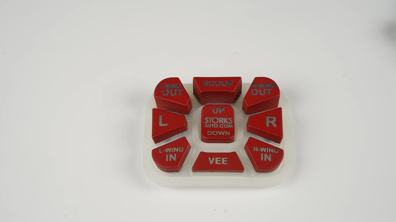
A coated laser-etched key is a small optical system. In the construction covered by this guide, the laser removes selected areas of one or more color layers so that a contrasting lower layer or light-transmitting silicone becomes visible. It does not need to engrave deeply into the molded key. This type of day/night marking uses selective top-layer ablation. Contrast, wavelength absorption, and consistent coating thickness shape the process window; KEYENCE treats coating removal as a material-specific laser process rather than a universal recipe. (TRUMPF, pp. 51–52; KEYENCE)
That distinction matters.
Canonical coated and backlit stack
Operator, glove, cleaning cloth, and contaminants
Optional clear protective coat — chemistry, cure, gloss, and flexibility
Opaque or multilayer color coat — off-state color and light blocking
laser-opened legend window
Translucent or contrasting molded silicone key
Production LED + diffuser/light guide + PCB + enclosure
Operator’s eye
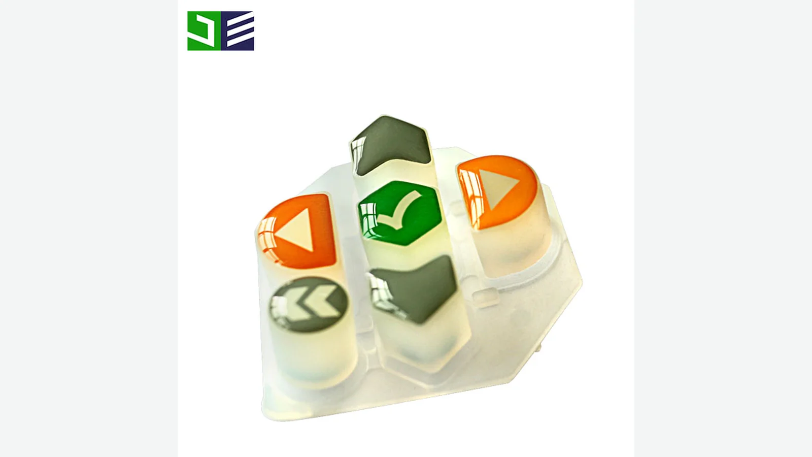
Shin-Etsu Polymer America publishes a representative five-layer HG construction—transparent silicone, a transmissive color layer, a dark coating, laser removal, and a protective overcoat. Diamond HMI shows a related option using translucent silicone, spray paint, laser etching, and a clear wear-resistant coat. These examples prove that the architecture exists; they do not define JASPER’s materials or a universal layer order. (Shin-Etsu Polymer America; Diamond HMI, pp. 3 and 6)
The drawing must say whether the clearcoat is applied after ablation, opened by the laser, or omitted. “Laser etched plus PU” is ambiguous because the same words can describe different interfaces and process sequences.
Choose the legend architecture before choosing a coating
| Construction | Best fit | What must be approved | When it is not the best choice |
|---|---|---|---|
| Laser-opened color coat | Day/night symbols, selective transmission, or high-contrast two-layer legends | Coat order, ablation window, off-state color, on-state light, edge quality, wear, and fluids | Unlit multicolor artwork is the main need, or no stable coating-to-silicone interface can be demonstrated |
| Printed legend with a clearcoat | Multiple visible colors, logos, or simple unlit labels | Ink/coating compatibility, print registration, clearcoat flexibility, wear, and chemical exposure | The legend must transmit tightly controlled backlight through an opaque field |
| Molded, recessed, or raised legend | Geometry-led marking that can be defined in tooling | Tool detail, readability, cleanability, and whether fill or printing is needed | Fine changing artwork, many language variants, or crisp illuminated windows are required |
| Insert-molded light window or opaque barrier | Strong optical isolation between adjacent keys or indicators | Insert bond, molding tolerances, light path, tooling, and assembled appearance | The added tooling and part architecture are not justified by the light-separation risk |
| Plastic cap over a silicone actuator | A hard touch surface or molded-in legend is more important than an all-silicone keytop | Cap retention, material compatibility, stack height, wear, and environmental fit | A one-piece sealed rubber surface, soft touch, or low profile is essential |
SiTECH documents a practical reason to consider the fourth route: a clear-silicone mat with an opaque exterior coat can still pass stray light through small unblocked regions, while molded opaque barriers can isolate individual light paths. That is not proof that insert molding always wins. It is a warning that coating opacity alone may not solve every light-bleed problem. (SiTECH, p. 8)
Four failure chains capture the decision boundary:
| Starting condition | Process effect | Next stress | Observable result to investigate |
|---|---|---|---|
| Variable color-coat build | The acceptable laser window narrows or shifts | Nominal ablation recipe | Incomplete removal, halo, ragged edge, or base-material damage |
| Uncontrolled preparation or cure | Silicone-to-coat or intercoat adhesion weakens | Fluid, heat, rubbing, or actuation | Edge lift, cracking, transfer, or loss of legend contrast |
| Coupon-only optical approval | Production LED, diffuser, PCB, and housing remain untested | Final integration | Dim areas, hot spots, color shift, or adjacent-key bleed |
| Topcoat selected only by resin-family name | Flexibility, cure, and intercoat compatibility remain unknown | Repeated key movement | Clearcoat cracking or delamination around the keytop |
These are mechanisms to investigate, not predictions that every part will fail. If the product needs a simple unlit multicolor mark, a hard capped key, or stronger optical isolation than a coated clear mat can provide, another route in the broader silicone rubber keypad family can be the cleaner decision.
2. A 9-Point Laser Etched Silicone Keypad Evaluation Framework
Evaluate the construction in this order: layer sequence, laser window, daylight appearance, powered appearance, adhesion and flex, dry wear, fluid-assisted wear, environmental conditioning, then change control. Later evidence cannot rescue an undefined layer stack. A bright sample cannot rescue weak adhesion. A large cycle number cannot rescue an undocumented test.
No single certificate closes all nine decisions.
2.1 Lock the coating system and layer order
A PU coated silicone keypad is not a standardized construction or durability class. “PU” identifies a broad polyurethane chemistry family, not the binder, crosslinker, one- or two-component architecture, preparation, primer, color coat, clearcoat, cure, thickness distribution, or intercoat sequence. Covestro’s coating overview distinguishes several one- and two-component polyurethane architectures with formulation-dependent properties. None is automatic evidence for a silicone key. (Covestro)
Ask the supplier to identify each functional layer and its process revision, even if exact formulations remain proprietary. Record what touches cured silicone, what blocks light, what the laser removes, what remains in the legend opening, and whether the final clear layer is applied before or after ablation. Shin-Etsu’s bonding guidance is a useful warning: adhesion to cured silicone is system-specific, and an evaluated primer may be needed depending on the adherend. (Shin-Etsu)
a controlled stack drawing, preparation/cure record, named layer functions, and representative samples from that exact sequence.
“PU coated” or “UV coated” is the entire specification.
2.2 Prove the laser window on the production stack
The laser must remove the intended layer across normal coating and geometry variation without damaging the lower coat or silicone. TRUMPF identifies coat contrast, absorption at the chosen wavelength, and homogeneous coat thickness as key inputs. It also describes a two-pass day/night strategy that leaves a small residual layer on the first pass and removes it at lower power on the second. That is one industrial strategy—not a mandatory recipe. (TRUMPF, pp. 51–52)
Qualify center and edge keys, high and low keytops, curved surfaces, narrow strokes, enclosed counters in letters, and dense icons. Inspect incomplete opening, wrong exposed color, halo, residue, rough edge, heat discoloration, and substrate damage. Record machine family, wavelength/optics, focus strategy, fixture revision, artwork revision, and approved recipe ID. Do not copy a minimum line width from another supplier; it depends on the actual coating, base, curvature, and optical requirement.
Map the margin.
a bounded recipe produces acceptable edges across representative keys and expected process variation.
one perfect flat sample is offered as proof of the production window.
2.3 Approve daylight color, gloss, texture, and edge quality
Off-state approval needs both measurements and human viewing. CIE 015:2018 defines standard colorimetric observers, illuminants, viewing conditions, coordinates, and color-difference practice. ASTM D2244-25 requires an agreed measurement procedure and recommends correlating instrumental tolerances with visual appraisal; gloss and texture can change commercial acceptability. ISO/CIE 11664-4:2019 defines CIE L*a*b* coordinates but does not supply a keypad-specific pass limit. (CIE; ASTM; ISO/CIE)
Use a flat witness coupon when an instrument cannot read a curved key repeatably, then inspect finished keys under a defined illuminant, distance, angle, and background. Freeze the reference master, color equation, gloss/texture description, and permitted edge defects. Do not invent a universal ΔE tolerance.
instrument data and controlled visual approval agree on a signed sample.
a digital artwork file or supplier photograph is the color master.
2.4 Approve backlit silicone keypad legends in the final optical stack
Backlit silicone keypad legends must be approved with the production LED bin, drive condition, diffuser or light guide, PCB, housing, light blocks, ambient condition, warm-up time, and viewing geometry. A coating opening that looks sharp on a light table can look dim, uneven, or leaky in the product. SiTECH’s guide documents how small clear-silicone paths can cause adjacent-key bleed and why molded opaque barriers may be useful. (SiTECH, p. 8)
Historical ASTM F2359 and F2360 made a related point: a color or luminance result measured on a partial backlit assembly applies only to that state and may change after further integration. Both methods are withdrawn—F2359 in 2023 and F2360 in 2024—so use the assembly-state principle, not a current-compliance claim. (ASTM F2359-04(2019); ASTM F2360-08(2015)e1; ASTM status catalogue)
Approve off-state contrast, on-state luminance and chromaticity, within-legend uniformity, key-to-key variation, hot spots, and light outside the intended opening. The OEM must set the numerical limits. The related backlit silicone rubber keypad guide covers the wider light-engine decision.
Test both states.
raw readings and photographs come from the intended production optical assembly.
approval uses a phone photo, an unspecified LED, or an un-housed keypad.
2.5 Separate coating adhesion from key flexibility
A coating can adhere to a flat coupon yet crack or lift when the key flexes. ASTM D3359-23 was developed for ductile coatings on metallic substrates, evaluates only lower adhesion levels, and is operator-sensitive; Precision and bias data are lacking for nonmetal substrates. ISO 2409:2020 is an empirical cross-cut classification, not a measurement of adhesion, and excludes textured coatings and total coating thickness above 250 μm. (ASTM D3359-23; ISO 2409:2020)
An adapted cross-cut or tape check can be a useful process screen when buyer and supplier document the specimen, cut spacing, tape, conditioning, pull, and classification. It cannot stand alone. Flex and actuate representative keys, including coating transitions near corners and webs, before and after fluid and environmental conditioning. Record whether failure occurred at silicone-to-coat, coat-to-coat, or clearcoat-to-color-coat interfaces.
the report identifies the interface, specimen geometry, conditioning, and adapted-method limits.
“5B adhesion” appears without substrate, coat build, tape, cure age, or key-flex evidence.
2.6 Test dry wear on contoured laser etched rubber keys
For laser etched rubber keys, the wear surface is the remaining coating and any clear topcoat around the opening. IEC 60068-2-70 is directly relevant because it covers rubbing of markings on flat or curved actuators and keyboards. The OEM still has to define severity, inspection, and failure. (IEC 60068-2-70)
ASTM F2357 and F3152 once covered relative abrasion comparisons on flat or contoured silicone rubber, but F2357 was withdrawn in 2017 and F3152 in 2023. Both warned that laboratory cycles do not equal a number of finger touches. ASTM D4060-25 remains active for organic coatings on plane, rigid surfaces; its result can screen a witness panel but cannot establish life on a curved, flexing key. (ASTM F2357-04; ASTM F3152-16; ASTM status catalogue; ASTM D4060-25)
Initial RCA comparison setup: Use the 175 g middle published load for supplier screening. Lock the wear paper, conditioning, inspection interval, endpoint, and acceptable appearance change for the project. Test cycles do not convert directly into field life. (Norman Tool; RCA correlation FAQ)
A usable report states the tip or abrasive medium, force, stroke, speed, path, conditioning, cycle count, inspection intervals, and endpoint. Photograph the same locations at each interval. Track first visible wear, coating breakthrough, edge erosion, transfer to the medium, color change, and powered optical change.
coupon screening is followed by the same documented rub on contoured production keys.
a bare “RCA cycles” or “Taber cycles” number is converted into years or finger presses.
2.7 Combine actual fluids with wiping and recovery
“Chemical resistant” is not an acceptance criterion. ISO 2812-4:2017 provides spot methods for liquid effects on coating systems. ASTM D1308-20(2025) records effects such as discoloration, gloss change, blistering, softening, swelling, and adhesion loss in continuous organic finishes exposed to household chemicals. IEC 60068-2-74 covers accidental fluid contact but explicitly does not demonstrate continuous-immersion suitability. (ISO 2812-4; ASTM D1308; IEC 60068-2-74)
Name the actual cleaner, disinfectant, oil, sunscreen, fuel, salt solution, or process fluid. Specify concentration, application quantity, contact mode, dwell, temperature, wipe material, wipe force or method, rinse, dry, recovery, repetitions, and acceptance criteria. Static spotting and wet abrasion answer different questions; use both when service includes soaking followed by wiping. Recheck tack, transfer, color, gloss, edge lift, adhesion, and backlit appearance after recovery.
production keys survive the named sequence with agreed before/after observations and measurements.
one unspecified “alcohol test” is used to approve every cleaner and concentration.
2.8 Condition the stack, but keep enclosure claims separate
Temperature, humidity, and UV can expose a weak interface before room-temperature rubbing does. IEC 60068-2-14:2023 provides change-of-temperature tests; it does not prescribe a universal keypad temperature range. ISO 16474-3:2021 exposes coatings to fluorescent UV, heat, and water under controlled cycles; it does not convert test hours into outdoor years. Repeat appearance, adhesion, rub, and powered-optical checks after the relevant conditioning. (IEC 60068-2-14; ISO 16474-3)
Keep ingress language equally precise. IEC 60529 classifies protection supplied by an electrical-equipment enclosure. ISO 20653:2023 does the same for road-vehicle electrical equipment. A loose silicone keypad, coating, or legend does not earn IP65, IP67, or any other complete-product rating. Compression, bezel geometry, housing, fasteners, cable exits, and any PCB or support structure that controls compression or sealing must be represented in the tested assembly. (IEC 60529; ISO 20653:2023)
conditioning matches the product specification, and ingress testing uses the intended assembled interfaces.
a material datasheet or loose-key test is promoted as finished-device environmental compliance.
2.9 Freeze traceability and reapproval triggers
The golden sample needs a data trail. Freeze silicone and pigment identifiers, surface preparation, primer status, coat sequence, cure, artwork, laser recipe revision, fixture, LED/optical stack, inspection method, and approved raw results. The supplier can protect proprietary formulas while still controlling revision IDs.
Require reapproval when a functional layer, material source, pigment, preparation, cure, laser machine or optics, artwork, LED bin, diffuser, housing, or test method changes. Cosmetic equivalence by eye is not enough when the change can alter adhesion, ablation, or light transmission.
Because a surface defect may originate at the silicone-to-primer, primer-to-color-coat, color-coat-to-clearcoat, or laser-opened edge, the qualification record should connect each specimen ID to its material lots, preparation timestamp, cure log, coat-build witness, laser recipe, fixture position, LED configuration, exposure history, and inspection images, allowing engineers to separate a formulation change from process drift or an optical-stack change before they authorize production.
signed samples and raw reports point to controlled process revisions.
substitutions are allowed under a generic “equivalent material” clause with no optical or coating requalification.
3. Run a Six-Step Buyer and Sample-Approval Process
The buyer process should narrow uncertainty in sequence. It starts with use conditions, moves through drawing and process control, then separates coupon screening from contoured-key and complete-assembly evidence. The signed golden sample comes last, not first.
Step 1 — Define the operating conditions and acceptance owner
List what the operator will see, touch, spill, wipe, and expect. Name who approves industrial design, optics, materials, reliability, and sourcing. If a condition has no owner, it usually reaches the supplier as “durable,” “chemical resistant,” or “uniform backlight”—phrases that cannot produce a reproducible test.
| Project input | What to record before sampling | Why it changes the decision |
|---|---|---|
| Legend artwork | Vector master, language variants, stroke geometry, filled areas, and revision | Controls edge detail, artwork registration, and laser program |
| Daylight appearance | Color reference, illuminant, viewing geometry, gloss/texture, defect limits | Separates measurable color from a supplier photograph |
| Powered appearance | LED bin, drive, warm-up, ambient, diffuser/light guide, housing, viewing geometry | Defines the optical assembly that must be approved |
| Contact and wear | Bare finger, glove, stylus, soil, wipe material, contact path, expected use pattern | Determines whether a coating coupon represents the real wear mechanism |
| Fluids | Exact cleaner, concentration, oil, disinfectant, sunscreen, salt solution, or other substance | Prevents a generic chemical panel from replacing the service exposure |
| Environment | Temperature transitions, humidity, UV, indoor/outdoor location, enclosure compression | Sets conditioning and complete-product boundaries |
| Decision criteria | Measurements, visual limits, failure definitions, sample size, report owner | Converts a good-looking prototype into an auditable approval |
Step 2 — Freeze the drawing and optical package
The mechanical drawing should identify key geometry, keytop curvature, coated zones, keep-outs, datums, legend location, orientation, and any molded light barriers. The artwork file should reference the same datums. Add a layer-stack detail that identifies the intended color layer, laser opening, and clearcoat sequence.
For a wider drawing review—actuation, contacts, housing, and assembly as well as legends—use the industrial keypad design checklist. Do not release the PCB LED layout independently if its position, height, or diffuser changes the accepted legend appearance.
Step 3 — Review the supplier’s material and process plan
Request controlled identifiers for the silicone/pigment system, preparation, primer status, color coat, optional topcoat, cure, laser equipment family, optics, recipe revision, fixture, and inspection plan. Proprietary formulas need not appear on the customer drawing, but the supplier’s internal revisions must be traceable to the sample report.
Ask one blunt question: which layer does the laser remove, and which layer is visible inside the finished legend? If the answer changes between engineering, sales, and the sample shop, the construction is not ready.
Step 4 — Screen flat witnesses and contoured keys separately
Flat witnesses can support color, transmission, coating-build, adhesion-screen, or rotary-abrasion work where the method requires a plane specimen. They are efficient development tools. They do not reproduce focus shift over a curved key, coating thinning at an edge, key flex, or the operator’s actual contact path.
Keep those results separate.
Include every geometry class that could change coating or laser behavior in a risk-based sampling plan. A single contoured key can screen a geometry during development, but it cannot establish batch variation or production qualification; the OEM and supplier must set sample quantities and lot coverage. Subject the planned keys to the defined dry and wet rub sequences, flex or actuation, and post-conditioning inspection. Keep witness and key results in the same report without treating them as interchangeable.
Step 5 — Qualify the production optical and mechanical assembly
Install the keypad on the intended PCB and housing with production-like compression, light blocks, diffuser or light guide, and LEDs. Measure and inspect both off and on states. For assemblies within the membrane-switch scope, ASTM F1578-24 provides an active contact-closure cycling method and recognizes visible deterioration such as ink delamination; otherwise define a project-specific actuator fixture and record its geometry, force profile, rate, and support. (ASTM F1578-24)
The site’s testing and quality-control overview provides the internal capability link for this stage. The final program still has to approve its own methods and limits. This is especially important for an industrial control interface where gloves, repeated cleaning, panel sealing, and low-light use may interact.
Step 6 — Sign the golden sample and change-control record
Retain off-state and powered photographs, raw measurements, exposure logs, wear images, material/process revision IDs, and the approved sample. The golden sample is a comparison artifact, not a substitute for numerical criteria. Define who can approve a deviation and which changes trigger partial or full requalification.
Use this staged test matrix
| Gate | Representative specimen and controlled inputs | Record and decision | Method boundary |
|---|---|---|---|
| Construction lock | Production silicone/pigment; exact layer functions; preparation, cure, laser and fixture revisions | Traceable stack and no unapproved substitution | Drawing/process audit; not a performance test |
| Daylight appearance | Finished keys plus flat witness; defined illuminant, geometry, reference | Color data, visual match, gloss/texture, coverage, edge defects | CIE 015 and ASTM D2244 support the procedure; buyer sets limits |
| Powered appearance | Production LED, drive, diffuser/light guide, PCB, housing, ambient, warm-up | Luminance/chromaticity, uniformity, key-to-key variation, bleed, hot spots | Use a documented project method; ASTM F2359/F2360 are withdrawn |
| Adhesion and flex | Finished key plus witness from the same preparation and cure | Interface of separation, edge lift, cracking before/after flex | ASTM D3359 and ISO 2409 require explicit applicability limits |
| Dry rub | Contoured production key; defined medium, force, stroke, speed, path, cycles | First wear, breakthrough, transfer, edge erosion, optical change | IEC 60068-2-70 is current; F2357/F3152 are legacy only |
| Wet or chemical rub | Same key geometry plus actual fluid, dwell, wipe and recovery | Tack, swelling, softening, transfer, color/gloss, adhesion, wear | Purchaser–supplier method based on the named exposure |
| Static fluid | Finished keys with actual fluid and specified contact mode | Visible and measured change after recovery | ISO 2812-4, ASTM D1308, or IEC 60068-2-74 as applicable |
| Actuation | Complete supported keypad/switch assembly | Coating/legend change plus mechanical and electrical checks | ASTM F1578-24 only when the assembly fits its scope |
| Temperature and UV | Complete assembly or representative coated keys and controls | Repeat appearance, adhesion, rub, and powered checks | IEC 60068-2-14 and ISO 16474-3 provide exposure, not life prediction |
| Ingress | Intended enclosure, compression, bezel, fasteners, exits, and any support that controls sealing | Complete-product ingress result | IEC 60529 or ISO 20653; never assign the result to a loose key mat |
The sequence matters. Chemical or environmental conditioning can change the surface before rubbing; actuation can open a crack that a flat adhesion screen never sees. Repeating optical and adhesion checks after conditioning produces more useful evidence than collecting unrelated one-time certificates.
4. Eight Release Blockers That Should Stop Sample Approval
These release blockers override an attractive prototype. Each one hides a missing test boundary, an uncontrolled interface, or evidence that cannot be transferred to the finished key.
| Disqualifying release blocker | Why approval should stop |
|---|---|
| The construction is described only as “laser etched with PU.” | The phrase does not identify layer order, preparation, primer, cure, what the laser removes, or whether the clearcoat is applied before or after ablation. |
| A withdrawn method is presented as current compliance. | ASTM F2357, F3152, F2359, and F2360 can explain legacy test architecture, but their withdrawn status must be disclosed. |
| An abrasion number has no test definition. | Without medium, force, path, speed, cycles, conditioning, specimen geometry, and endpoint, the number cannot be reproduced or compared. |
| A flat coupon is the only coated specimen. | Plane witnesses cannot reveal focus shift, edge coat variation, flex cracking, or wear on a contoured keytop. |
| “Chemical resistant” replaces the fluid list. | An unnamed alcohol wipe says nothing reliable about the actual disinfectant, oil, sunscreen, salt solution, concentration, dwell, or wiping sequence. |
| The backlight sample omits production optics. | A bench light or phone photograph cannot approve the intended LED, current, diffuser, housing, temperature, viewing geometry, or adjacent-key bleed. |
| A loose keypad carries an IP rating. | IEC 60529 and ISO 20653 apply to enclosures; the intended compression, bezel, housing, fasteners, PCB, and exits must be part of the test. |
| There is no golden-sample traceability or change control. | An unrecorded material, pigment, cure, laser, coating, artwork, or LED change can invalidate optical, adhesion, and wear evidence. |
Rejecting an incomplete report is cheaper than arguing later about what “durable” meant.
5. Frequently Asked Questions
What is a laser etched silicone keypad?
In the coated day/night construction covered here, a laser etched silicone keypad is a molded silicone keypad whose visible legend is created by selectively removing a surface color layer. The opening reveals a contrasting lower layer or a light-transmitting silicone base. Other laser-marking constructions can use a different layer sequence or mechanism, so the drawing must define the coating order, exposed layer, ablation depth, and optional protective topcoat.
When is laser etching better than printing on silicone keys?
Laser etching is usually the better route for controlled day/night legends or selective backlight transmission through an opaque field. Printing is often the cleaner route for unlit, multicolor graphics. Neither method is universally more durable. The complete ink or coating system, key geometry, wear path, fluids, cure, and acceptance test decide which construction fits the product.
Can a laser-etched legend wear off?
In the coated day/night construction covered here, the removed portion of the top color coat cannot peel because it is no longer present. The exposed lower layer, any clearcoat spanning the opening, and the surrounding coating interfaces can still abrade, soften, crack, or delaminate. A “permanent legend” claim is therefore incomplete unless representative keys pass the defined dry wear, fluid-assisted wear, flex, environmental, and optical checks.
Does a PU coated silicone keypad automatically last longer?
No. PU identifies a polyurethane chemistry family, not a finished performance level. Durability depends on the specific binder and crosslinker, silicone preparation, primer, color coat, intercoat compatibility, cure, coat build, key flex, fluids, and wear method. Approve the disclosed system on the production silicone and geometry; do not approve the resin-family name by itself.
How should backlit silicone keypad legends be approved?
Approve them in both off and on states using the production LED bin, drive condition, diffuser or light guide, PCB, housing, light blocks, ambient condition, warm-up time, and viewing geometry. Set project limits for color, luminance, uniformity, key-to-key variation, hot spots, and light leakage. A phone photograph or light-table sample is not a repeatable optical method.
Which abrasion test applies to laser etched rubber keys?
IEC 60068-2-70 is current and directly addresses finger-and-hand rubbing of markings on flat or curved actuators and keyboards. ASTM D4060 applies to plane, rigid coated specimens, so it is a witness-panel screen. ASTM F2357 and F3152 covered relevant relative abrasion architectures but are withdrawn. The buyer and supplier must document geometry, medium, force, path, speed, cycles, and endpoint.
Can a loose silicone keypad be rated IP65 or IP67?
No. IEC 60529 assigns ingress protection to an enclosure, and ISO 20653 applies that concept to road-vehicle electrical-equipment enclosures. A representative test assembly must include the intended keypad compression, bezel, housing, fasteners, cable exits, and any PCB or support structure that controls compression or sealing. A loose rubber mat or coating result cannot establish the finished device’s IP code.
What should an OEM provide before legend and coating samples are made?
Provide vector artwork and datums, key geometry, layer intent, day and powered appearance references, the production LED and optical stack, actual fluids and wipe sequence, environmental conditions, wear path, acceptance criteria, sample quantities, and change-control expectations. Name who approves industrial design, optics, reliability, and sourcing so conflicting sample comments are resolved before release.
6. Review Legend and Coating Samples Before Release
Review a sample ladder, not one finished beauty sample: the molded base, a color-coated unlasered control, a laser-opened key before the final clear layer when that intermediate state exists, the finished contoured keys, and the complete powered assembly. Compare the same key locations in daylight and powered conditions before and after the agreed fluid, rub, flex, and environmental sequence.
JASPER can be included as one manufacturer option for this legend-and-coating review after the proposed stack, specimens, methods, and change-control record are disclosed. The approval should follow the evidence regardless of supplier: clean artwork cannot compensate for an unstable laser window, and a hard coating label cannot compensate for weak interfaces.
Next action: send the controlled artwork, layer intent, production optical stack, actual exposure list, and initial acceptance matrix for sample review. Do not release the construction until the day-state appearance, powered-state appearance, coating interfaces, and post-conditioning results all point to the same approved revision.
Technical References
- Source: TRUMPF Laser Marking Technical Booklet. Accessed 2026.
- Source: KEYENCE Laser Ablation Application Guidance. Accessed 2026.
- Source: IEC 60068-2-70 Marking and Lettering Abrasion. Accessed 2026.
- Source: ASTM D4060-25 Organic Coating Abrasion. Accessed 2026.
- Source: ISO 2812-4:2017 Coating Liquid Resistance. Accessed 2026.
- Source: ASTM D1308-20(2025) Household Chemical Effects on Coatings. Accessed 2026.
- Source: IEC 60068-2-74 Fluid Contamination. Accessed 2026.
- Source: ISO 16474-3:2021 Fluorescent UV Exposure of Coatings. Accessed 2026.
- Source: IEC 60068-2-14:2023 Change of Temperature. Accessed 2026.
- Source: ISO 20653:2023 Road Vehicle Enclosure Protection. Accessed 2026.
- Source: TRUMPF. Accessed 2026.
- Source: KEYENCE. Accessed 2026.
- Source: Shin-Etsu Polymer America. Accessed 2026.
- Source: Diamond HMI. Accessed 2026.
- Source: SiTECH. Accessed 2026.
- Source: Covestro. Accessed 2026.
- Source: Shin-Etsu. Accessed 2026.
- Source: CIE. Accessed 2026.
- Source: ASTM. Accessed 2026.
- Source: ISO/CIE. Accessed 2026.
- Source: ASTM F2359-04(2019). Accessed 2026.
- Source: ASTM F2360-08(2015)e1. Accessed 2026.
- Source: ASTM status catalogue. Accessed 2026.
- Source: ASTM D3359-23. Accessed 2026.
Review the keypad construction before tooling release
Send the drawing, key geometry, force targets, contact stack, artwork, housing, environment, and approval plan for a construction-specific review.